
 Open Access Article
 This Open Access Article is licensed under a Creative Commons Attribution-Non Commercial 3.0 Unported Licence
Manganese(II) phosphate nanosheet assembly with native out-of-plane Mn centres for electrocatalytic water oxidation†
Hongfei
Liu‡
a,
Xueqing
Gao‡
a,
Xiaolong
Yao‡
b,
Mingxing
Chen
c,
Guojun
Zhou
a,
Jing
Qi
a,
Xueli
Zhao
a,
Weichao
Wang
 *b,
Wei
Zhang
*a and
Rui
Cao
*ac
*b,
Wei
Zhang
*a and
Rui
Cao
*ac
aKey Laboratory of Applied Surface and Colloid Chemistry, Ministry of Education, School of Chemistry and Chemical Engineering, Shaanxi Normal University, Xi'an 710119, China. E-mail: zw@snnu.edu.cn; ruicao@ruc.edu.cn
bDepartment of Electronics, Nankai University, Tianjin 300071, China. E-mail: weichaowang@nankai.edu.cn
cDepartment of Chemistry, Renmin University of China, Beijing 100872, China
First published on 2nd October 2018
Abstract
Nature selects Mn-clusters as catalysts for water oxidation, which is a significant reaction in photosynthesis. Thus, it is of critical importance to develop Mn-based superstructures and study their catalytic details for water-splitting-based renewable energy research. Herein, we report a manganese(II) phosphate nanosheet assembly with asymmetric out-of-plane Mn centers from the transformation of amine-intercalated nanoplates for efficient electrocatalytic water oxidation in neutral aqueous solutions. From structural and computational studies, it is found that the native out-of-plane Mn centers with terminal water ligands are accessible and preferential oxidation sites to form active intermediates for water oxidation. In addition, the asymmetry can stabilize the key MnIII intermediate, as demonstrated by electrochemical and spectrometric studies. This study delivers a convenient strategy to prepare unique nanosheet assemblies for electrocatalysis and fundamental understandings of oxygen evolution chemistry.
Introduction
Hydrogen is an energy carrier with high gravimetric energy density. Compared with traditional methods, electrocatalytic water splitting by sustainable electricity represents a green approach to produce hydrogen.1,2 In water splitting, the oxygen evolution reaction (OER) is challenging due to the high energy barriers for the breaking of O–H bonds and the attendant formation of O–O bonds.3 Thus, it is significant to understand the inherent limiting factors of the OER toward advanced water splitting. Interestingly, natural systems selected Mn-based clusters as water oxidation catalysts to produce oxygen powerfully under neutral conditions.4,5 Therefore, studies on Mn-based catalysts are critical to understand the detailed mechanism of water oxidation and to guide the development of functional artificial water splitting systems.A variety of MnOx polymorphs have been developed for chemical, electrochemical and photochemical water oxidations.6–9 The framework structure, Mn geometry, Mn valence and surface structure are mutually important for the efficiency of water oxidation.10–13 Substantial Mn-based oxide catalysts transform into layered structures with out-of-plane or boundary undercoordinated units as effective catalytic sites,14,15 which has been further demonstrated by detailed computational studies and X-ray absorption spectroscopy analyses by Mattioli and co-workers.16 These active centres are typically associated with lattice defects. Therefore, it will be very promising and challenging to rationally design Mn-based materials with native out-of-plane Mn centres for the OER, which has yet not been reported to the best of our knowledge. In addition, it is generally acknowledged that the MnIII species is the key catalytic intermediate for the OER.17,18 Dismukes and co-workers present detailed studies on the coordination geometry of MnIII sites as the origin of the OER activity in several Mn-based materials. Specifically, the flexible out-of-plane corner-sharing Mn3+O6 sites are substantially more active than buried edge-sharing Mn3+O6 centres.10 Recently, Nocera and co-workers also reported the introduction of MnIII into an activated δ-MnO2 film.19 However, the major problem of the OER-active MnIII species is its instability in a symmetric octahedral geometry. In many Mn-based oxides, MnIII has an electronic configuration of t2g3eg1, which can induce significant Jahn–Teller (J–T) distortion.20,21 In neutral solutions, MnIII intermediates are inclined to disproportionate into MnII and MnIV species, neither of which is a significant contributor in water oxidation.22,23 To address this issue, asymmetry was introduced into the Mn geometry.24 The asymmetry in the crystal frameworks can tolerate J–T distortion and thereby stabilize the MnIII intermediate. Thus, we are interested in bringing structural asymmetry in Mn-based materials with native out-of-plane Mn centres for the OER.
We herein report the synthesis of an ultrathin manganese(II) phosphate nanosheet assembly (denoted as MnPi hereafter) from the transformation of amine-intercalated nanoplates for efficient electrocatalytic water oxidation in neutral aqueous solutions (Fig. 1). First, ethylene-diammonium manganese phosphate layered nanoplates (denoted as Mn-LNPs hereafter) with weak interlaminar van der Waals bonds were prepared by a hydrothermal method. Next, a freestanding MnPi nanosheet assembly is obtained from the layered Mn-LNP precursor in water via liquid-phase ultrasound treatment. Instead of forming conventional isolated nanosheets by exfoliation, the ultrathin 2D nanosheets curled together as substructures to form a novel superstructure assembly.25,26 The resulting MnPi showed high OER activity in neutral solutions because of the following reasons. First, the 2D ultrathin nanosheet substructure can offer abundant surface sites and excellent anisotropic charge transfer.27 The 3D freestanding superstructure is beneficial to facilitating mass diffusion.28,29 Second, the asymmetry in the Mn geometry generated by the phosphate and water ligands can tolerate the J–T distortion of the MnIII intermediate. Last, there are layers with native out-of-plane Mn centres bearing terminal H2O ligands, which resemble the hexagonal polymorph of δ-MnO2 and can function as ideal reaction sites for water oxidation.
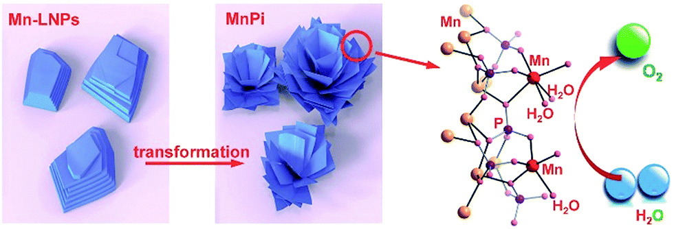 | ||
| Fig. 1 Ultrathin MnPi nanosheet assembly with native asymmetric out-of-plane Mn centres (red) derived from the transformation of layered phosphates for electrocatalytic water oxidation. | ||
Results and discussion
The morphologies of Mn-LNPs and the sonication-derived MnPi were examined using scanning electron microscopy (SEM) and transmission electron microscopy (TEM) techniques (Fig. 2 and S1–S6, ESI†). Mn-LNPs display a layered structure with a planar size at the micron level. The layered Mn-LNPs were obtained by a hydrothermal reaction of MnCl2, H3PO4 and ethylenediamine (EDA) at a precise pH value of 5. The EDA cations were intercalated into the manganese phosphate layers.30 The intercalation of the large organic cations between layers is beneficial for subsequent liquid-phase ultrasound transformation.26 In the treatment, water was chosen as the suitable liquid medium to produce the 3D MnPi assembly with freestanding 2D nanosheets as the substructure. Instead of forming isolated nanosheets, the derived nanosheets curled together to form the superstructure, which combines the advantages of 2D and 3D materials in electrocatalysis.31 The 2D substructure provides abundant surface sites and superior charge transfer ability.32,33 The 3D superstructure prevents the free accumulation of nanosheets on the electrode surface and thereby brings about efficient mass transport during catalysis.34 Ultrasound transformation in water shows the advantages of simple operation, low cost and negligible pollution and is favourable for subsequent electrocatalytic experiments in aqueous solutions.26,35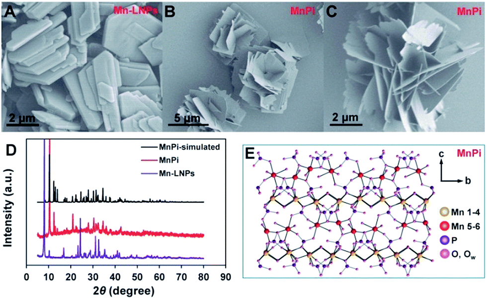 | ||
| Fig. 2 The SEM images of the as-prepared Mn-LNPs (A) and MnPi (B and C). (D) XRD patterns of the as-prepared Mn-LNPs and MnPi, and simulated XRD patterns of MnPi from crystal structure data. (E) The crystal structure of MnPi with six different Mn sites, including Mn(1–4) layers and out-of-plane Mn(5,6) centres. | ||
The TEM images of the samples are displayed in Fig. S6 (ESI†), showing the thick planar layered structure of Mn-LNPs. After sonication, a thin nanosheet structure can be observed. Scanning transmission electron microscopy (STEM) and energy dispersive X-ray spectroscopy (EDX) elemental mapping were conducted to testify the elemental distributions of Mn-LNPs and MnPi (Fig. S6, ESI†). The EDX signal of N in MnPi obviously decreases. Elemental analysis results also indicate the largely reduced carbon and nitrogen contents after phase transformation (Table S1, ESI†). Thus, the weak interlayer interaction between adjacent manganese phosphate layers in Mn-LNPs is broken by the removal of EDA. Subsequently, assembly with manganese phosphate nanosheets is formed by sonication. The average thickness of the sonication-derived MnPi nanosheets is ∼3.4 nm, whereas the average thickness of Mn-LNPs is ∼24 nm from atomic force microscopy studies (Fig. S7, ESI†).
The crystal phases of Mn-LNPs and MnPi were analyzed by X-ray diffraction (XRD) characterization (Fig. 2D). The crystalline phase of Mn-LNPs can be indexed to reported crystal structures of (C2H10N2)[Mn2(HPO4)3]·H2O, which is a layered material with intercalated amine molecules between the phosphate layers.36 The strong diffraction peak at 8.0° indicates the long-range well-organized stacking of manganese phosphate layers. The thermal gravimetric analysis (Fig. S8, ESI†) shows similar weight losses to reported results.36 The molar ratio of Mn![[thin space (1/6-em)]](https://www.rsc.org/images/entities/char_2009.gif) :P in Mn-LNPs is 2:3.01 based on the EDX analysis. The XRD patterns of MnPi (red line) match well with the patterns of metaswitzerite (Mn4Fe1.75(PO4)4·8H2O, monoclinic, P21/c).37 The high-resolution image of the XRD patterns with the standard lines from PDF #20-0713 is provided in Fig. S9 (ESI†). Our nanosized material is composed of ultrathin 2D structures with specified orientations of crystal facets. Thus, the XRD peak intensities of our sample should not match well with the simulated result of perfect crystals. Nevertheless, we can still correlate almost all the peak positions between the observed and simulated XRD results to identify the crystal structure of the synthesized material. In addition, the molar ratio of Mn:P in MnPi is 3:2.02 based on the EDX analysis. The temperature dependent magnetic susceptibility of MnPi indicates a high spin Mn(II) state (Fig. S10, ESI†).38 These results indicate that the as-prepared MnPi is an analogue of the reported metaswitzerite with the same crystal structure. Thus, it is possible to illustrate the structure of the as-prepared Fe-free MnPi analogue based on the crystal structure of metaswitzerite. The simulated XRD pattern of the MnPi metaswitzerite structure (ICSD-100263) is shown in Fig. 2D (black line), demonstrating the structural consistency between the metaswitzerite and the as-prepared MnPi.
:P in Mn-LNPs is 2:3.01 based on the EDX analysis. The XRD patterns of MnPi (red line) match well with the patterns of metaswitzerite (Mn4Fe1.75(PO4)4·8H2O, monoclinic, P21/c).37 The high-resolution image of the XRD patterns with the standard lines from PDF #20-0713 is provided in Fig. S9 (ESI†). Our nanosized material is composed of ultrathin 2D structures with specified orientations of crystal facets. Thus, the XRD peak intensities of our sample should not match well with the simulated result of perfect crystals. Nevertheless, we can still correlate almost all the peak positions between the observed and simulated XRD results to identify the crystal structure of the synthesized material. In addition, the molar ratio of Mn:P in MnPi is 3:2.02 based on the EDX analysis. The temperature dependent magnetic susceptibility of MnPi indicates a high spin Mn(II) state (Fig. S10, ESI†).38 These results indicate that the as-prepared MnPi is an analogue of the reported metaswitzerite with the same crystal structure. Thus, it is possible to illustrate the structure of the as-prepared Fe-free MnPi analogue based on the crystal structure of metaswitzerite. The simulated XRD pattern of the MnPi metaswitzerite structure (ICSD-100263) is shown in Fig. 2D (black line), demonstrating the structural consistency between the metaswitzerite and the as-prepared MnPi.
The crystal structure of the MnPi is illustrated in Fig. 2E and S11–S14 (ESI†). The following information can be concluded. First, six different Mn sites are determined. Second, 6-coordinated Mn(1), Mn(2), Mn(3), and Mn(4) octahedrons are connected to form a compact layer parallel to the (001) plane. In this layer, each Mn octahedron is surrounded by the other three different Mn octahedrons. On average, every Mn atom in this layer has two bridging water ligands, each of which connecting two Mn atoms via the μ2-Ow bridge. Third, the 5-coordinated Mn(5) trigonal bipyramid and 6-coordinated Mn(6) octahedron, as out-of-plane Mn centres, form another layer parallel to the above-mentioned layer. Of particular note is that Mn(5) has one terminal coordinated water molecule and Mn(6) has two terminal coordinated water molecules. These coordination sites with terminal water molecules are critical in water oxidation. The terminal water on Mn(5,6) can participate in water oxidation to form O2. After the release of O2, the coordination sites will be available for new water molecules. In addition, 5-coordinated Mn is widely reported in MnOx materials as the active centre for water oxidation.16 In our MnPi, the Mn(5) trigonal bipyramid is highly distorted with one terminal water-coordination. This structure is essentially promising for water oxidation.17 The structures of the Mn coordination with Mn–O bond lengths are shown in Fig. S14 (ESI†). As can be seen, the Mn(6) has the lowest symmetry in terms of Mn–O bond lengths in the five 6-coordinated Mn atoms (Mn(1–4) and Mn(6)). Meanwhile, Mn(5) is 5-coordinated and should have the highest tolerance for the MnIII distortion. The HRTEM image of the basal plane is shown in Fig. S15 (ESI†), indicating the lattice spacing of the (400) facet. Thus, the most exposed sites are either the Mn(1–4) layer or the parallel Mn(5,6) layer depending on the termination of the sheet along the c-axis. Considering the average thickness of the nanosheet at ∼3.4 nm, one sheet contains around 4 Mn(1–4) layers plus 4 Mn(5,6) layers in tandem.
The electrocatalytic water oxidation performance of MnPi was evaluated in a 0.05 M phosphate buffer (pH = 7) by cyclic voltammetry (CV). As shown in Fig. 3A, the catalytic performance of MnPi is much better than that of MnO, which has the same Mn valence. It requires an overpotential of 563 mV to reach an OER current density of 1 mA cm−2 in a neutral aqueous solution on a glassy carbon electrode. This performance is among the top values reported in the literature for Mn-based OER electrocatalysts, as shown in Table S2 (ESI†).5,6,11,12,18 However, we have to note that some of these studies focus on the detailed mechanism studies rather than the optimization of OER activity. A remarkable quasi-reversible redox peak is detected with Epa = 0.9 V vs. the normal hydrogen electrode (NHE, all potentials are versus NHE unless otherwise stated), which is assigned to the MnII/III couple.22,23 The reverse cathodic scan of the CV plot displays two consecutive reduction peaks, which are probably due to the two-step reduction of MnIV species to MnII or the reduction of two different MnIII species to MnII. Differential pulse voltammetry (DPV) is adopted to gain more details of the precatalytic features (Fig. 3B). Of particular note is that an additional oxidation peak, which is absent in MnO, can be detected at around 1.12 V following the MnII/III oxidation of MnPi. As reported in the literature, the MnIII state in Mn-based oxides is unstable under neutral conditions (due to the J–T distortion of the symmetric MnIII coordination) by involving disproportionation into MnII and MnIV.23 Thus, it is reasonable to observe the absence of the oxidation of MnIII into higher valence states in MnO, which has a symmetric Mn coordination.39 The stabilization of the MnIII state and its consequent oxidation into higher states in MnPi is one of the reasons for the much improved catalytic activity, as compared with MnO. The OER is triggered by further oxidation at higher potentials after the second oxidation of MnPi. This further oxidation is generally recognized as the formation of active –MnV![[double bond, length as m-dash]](https://www.rsc.org/images/entities/char_e001.gif) O (formal oxidation states) species.4,40 In addition, the performance of MnPi is also much better than that of Mn-LNPs (Fig. S16, ESI†). The electrochemical surface areas (ECSA) of MnPi, Mn-LNPs and MnO are provided in Fig. S17 (ESI†). As expected, the MnPi has the highest ECSA. Taking into consideration the ECSA, the normalized activity is provided in Fig. S18 (ESI†), showing the highest intrinsic OER activity of MnPi as a result of the Mn geometry. In particular, the MnO does not contain asymmetric Mn centres and the Mn-LNPs does not contain coordinated water molecules.
O (formal oxidation states) species.4,40 In addition, the performance of MnPi is also much better than that of Mn-LNPs (Fig. S16, ESI†). The electrochemical surface areas (ECSA) of MnPi, Mn-LNPs and MnO are provided in Fig. S17 (ESI†). As expected, the MnPi has the highest ECSA. Taking into consideration the ECSA, the normalized activity is provided in Fig. S18 (ESI†), showing the highest intrinsic OER activity of MnPi as a result of the Mn geometry. In particular, the MnO does not contain asymmetric Mn centres and the Mn-LNPs does not contain coordinated water molecules.
 | ||
| Fig. 3 (A) The CV and (B) DPV curves of the MnPi and MnO electrocatalysts. (C) The current and potential response of the MnPi electrocatalyst to the pH values of the electrolyte. (D) The plots of the potentials at Epa(MnII/III) and j = 0.3 mA cm−2 against the pH values of the electrolyte. (E) The CV curves of the MnPi sample in H2O and D2O. (F) The current and potential response of the MnPi electrocatalyst to the concentration of phosphate anions. (G and H) The in situ UV-vis absorbance of the MnPi and MnO electrocatalysts under OER conditions at different applied potentials. The spectra at 0.5 V were used as the reference. (I) The UV-vis absorption spectra of the pyrophosphate (pp) solution after 2 h electrolysis with MnPi and MnO electrocatalysts. | ||
The current–potential responses of i, i/ν and  are recorded to analyse the controlling processes of the pre-catalysis and catalysis in MnPi (Fig. S19, ESI†).41 The following information can be concluded. First, the quasi-reversible MnII/III redox couple becomes reversible at high scan rates (Fig. S19A, ESI†), indicating that the resting states can be fully regenerated after the completion of the catalytic cycle and the resting states are sensitive to its surroundings (electrolyte, oxygen, etc.). Second, the material displays semiconducting behaviour within the complete precatalytic potential range, which is consistent with the nature of transition metal phosphates. Third, the currents before the first oxidation (i ∝ ν region, Fig. S19B, ESI†) are kinetic-controlled by double-layer capacitance (∼30.9 μF). After that, the currents are generally kinetic-controlled by diffusion (
 region, Fig. S19C, ESI†), indicating that there is still room for increasing the structure voids in the layered MnPi toward higher performance.
To shed more light on the pre-catalysis and catalysis, the current responses to the nature of the buffer solutions are recorded under similar conditions (Fig. 3C–F). As shown in Fig. 3C, the MnII/III oxidation is dependent on the pH values of the electrolyte. The Epa values have a linear relationship with pH values with a slope of −66.4 mV pH−1, indicating a ne−/nH+ proton-coupled electron transfer (PCET) process (the theoretical value of such a process is −59 mV pH−1).42 In detail, the MnII/III oxidation is associated with the removal of one proton from the coordinated water/hydroxyl. The phosphate anions and μ2-Ow in the material are beneficial for this oxidation process due to their proton-binding ability.43 Meanwhile, the catalytic currents are also dependent on the pH values of the electrolyte. At a current density of 0.3 mA cm−2, the required potential is proportional to the pH values with a linear slope of −107.4 mV pH−1. In this catalytic region, the Tafel slope is determined to be 237.2 mV dec−1 (Fig. S20, ESI†). An inverse reaction order close to 0.5 on proton activity is calculated based on eqn (S1) (ESI†). This value would result from the combination of two primary competing pathways of zeroth-order and inverse first-order [H+] dependence.42 Thus, the rate-determining step (rds) in the latter pathway may involve the nucleophilic attack on –MnVO (formal oxidation states) by a water molecule (a proton is generated as the product).3 This hypothesis is further proved by the kinetic isotope effect (KIE) experiment (Fig. 3E). The OER rate is much slower in a D2O solution, indicating that the removal of protons is involved in the rds.21 In addition, the current of the MnII/III oxidation also indicates a KIE, which is consistent with the abovementioned PCET feature of the oxidation. The Nyquist plot of MnPi derived from the electrochemical impedance spectroscopy is shown in Fig. S21 (ESI†), indicating a poor conductivity of the inorganic phosphate. The current dependence on phosphate concentration is shown in Fig. 3F. The results indicate that the Epa position (MnII/III) and the catalytic current are independent of the buffer concentration. As compared with the results in electrolytes with lower concentrations, the Epa of the sample recorded in 0.05 M phosphate buffer solution is affected by the capacitance or further oxidation events due to the diffusion limitation of the substances. The peak intensities are mainly affected by the background currents arising from different specific capacitances in buffer solutions of different concentrations. In some cases, lower concentrations of electrolyte can cause higher capacitances.44 The role of phosphate anions in promoting the PCET process is demonstrated by the much higher Tafel slope in a NaClO4 solution (Fig. S22, ESI†).45
The stability of the MnPi catalyst was evaluated by controlled potential electrolysis (Fig. S23, ESI†), showing a stable OER current within 20 h. In contrast, the MnO sample displayed lower current density with inferior stability. The core X-ray photoelectron spectroscopy (XPS) spectra of the MnPi (green line), Mn-LNPs (purple line) and MnPi after electrolysis (blue line) are displayed in Fig. S24A–C (ESI†). The peak positions of the Mn spectra remained almost unchanged, indicating the structural stability of Mn coordination after sonication and electrolysis. The peak position of the Mn 2p3/2 (641–642 eV), the presence of the satellite peak of Mn 2p3/2 (∼647 eV), and the peak splitting of the Mn 3s spectra at ∼6.2 eV all demonstrate that the valences of Mn in the materials are two.46 Of particular note is that the N 1s spectra of these three samples changed obviously. The strong N 1s signal of the Mn-LNPs (∼401 eV) is from the intercalated EDA. This peak is significantly reduced after the sonication treatment, as shown in the N 1s spectrum of the MnPi. The amine molecules were removed by sonication, and the layered nanoplates were converted into thin nanosheets. After electrolysis, two new N 1s peaks emerged at 407.5 and 400.0 eV. These two peaks are assigned to the signal of surface adsorbed nitrates and ammonia, respectively.47 For metal cations of the first-transition series, the binding energy of the 2p3/2 shake-up satellite peak decreases when the electronic configuration changes from d4 to d5. Thus, the 2p3/2 satellite peak appears at lower binding energy for MnII (d5). The 2p3/2 satellite peak of MnIII (d4) will appear at higher binding energy, overlapping with its 2p1/2 peak.48 In addition, the energy splitting value of Mn 3s will decrease significantly from MnII to MnIII because of unpaired 3d electrons in MnII.49 The XPS splitting of the Mn 3s peaks of our catalyst is 6.2 eV, which is a signature value of Mn(II). The fitted Mn 2p, O 1s and P 2p spectra are provided in Fig. S25 (ESI†). Besides the unchanged Mn 2p and P 2p peaks, there is a dominant O 1s peak centered at ∼532.5 eV from the catalyst after electrolysis. This peak with relatively high binding energy is likely from the oxidation of the surface organic compounds. The XPS results of the above-mentioned samples clearly demonstrate the stability of the coordination environment of the Mn sites in the material when it is subjected to sonication and electrolysis. The CHNS elemental analysis results of the investigated samples are provided in Table S1 (ESI†), showing that C and N are present in Mn-LNP and they largely decrease in MnPi. The Mn:P ratio of the MnPi sample before and after electrolysis is analyzed by ICP-OES, showing a stable composition (Table S3, ESI†). We performed SAED of the MnPi before and after electrolysis under a low magnification. As shown in Fig. S26,† the diffraction patterns from the samples can match with the powder XRD patterns. The holes displayed in the TEM images are caused by the electron beam. These results further demonstrate the stability of the sample.
The capture of the MnIII intermediate state in electrocatalysis is critical to understand the OER process. The MnPi catalyst was loaded on a transparent indium tin oxide (ITO) electrode to examine its in situ UV-vis absorbance under electrocatalysis. As shown in Fig. 3G, the MnPi sample displays increased absorbance of UV and visible light at ∼310, ∼390 and ∼590 nm when the applied potential is increased from 0.8 V to 1.0 V. The absorbance at 0.5 V (open circuit potential) is used as the reference spectrum. The absorbance at ∼390 nm is associated with the ligand-to-metal charge transfer (LMCT) between O2− and Mn3+, indicating the formation of the MnIII intermediate.50 A broad peak at ∼590 nm becomes significant when the applied potential is higher than 1.4 V. This broad peak is attributed to the d–d transitions of MnIV or species with even higher Mn valence states, which usually have associated sharp LMCT absorbance at ∼400 nm.39 In contrast, the MnO sample displays a much weaker absorbance signal of oxidized Mn species, indicating the poor stability of MnIII in symmetric complexation (Fig. 3H).39 The presence of the MnIII intermediate in the MnPi catalyst during electrolysis is further identified by the determination of the MnIII-pyrophosphate (pp) complex, which has a characteristic LMCT absorption at 258 nm.50 After 2 h water electrolysis in a 20 mM pp solution, the solution from the MnPi catalyst shows clear characteristic absorption from MnIII-pp (green line, Fig. 3I). In contrast, the solution from the MnO catalyst displays negligible relevant absorption, which is consistent with the results from the in situ UV-vis spectra.
The first-principles density functional theory (DFT) calculations were performed to determine the active Mn centre in the MnPi. The conventional cell has eight chemical formula units including 200 atoms in total (Fig. 4 & S27, ESI†). The charge difference on the Mn atoms after the removal of one electron from the cell is referred to as the index of the order of difficulty in the oxidation of Mn sites. The top three Mn sites with the largest reduced valence charges are marked by yellow circles in Fig. 4. Interestingly, two of them are the 6-coordinated Mn(6) sites with two terminal water molecules, and the remaining one is the 5-coordinated Mn(5) site with one terminal water molecule. These Mn centres are the out-of-plane sites to the compact Mn(1)–Mn(4) octahedron layer. In addition, the coordinated terminal water molecules can further facilitate the oxidation of the corresponding Mn centres by providing a disposable proton.3 The coupled removal of one proton can significantly reduce the required energy for the removal of one electron from the metal centre.51,52 This proton-coupled electron transfer widely exists in biological systems involving oxygen chemistry. As a result, the Mn(5) and Mn(6) centres have several advantages in catalysing water oxidation. First, they have coordinated terminal water molecules to provide vacant sites for OER substances. Second, they can be oxidized at low potentials to form the Mn(III) intermediate state.
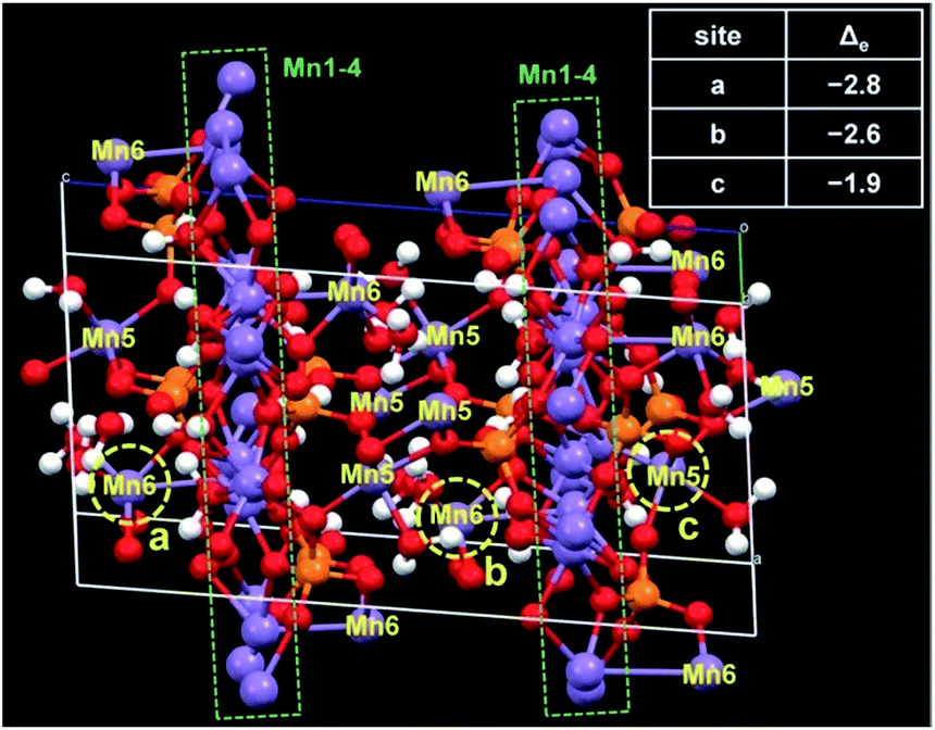 | ||
| Fig. 4 The unit cell of the MnPi used to calculate the preference of the oxidation of different Mn sites. The three Mn sites that can be most easily oxidized are marked with the yellow circles. The corresponding charge differences of these Mn sites after the removal of one electron are listed in the table. | ||
Conclusions
In summary, a MnPi nanosheet assembly is prepared from the transformation of amine-intercalated manganese phosphate nanoplates for an efficient electrocatalytic OER in neutral aqueous solutions. Under controlled conditions, the sonication-derived nanosheets are not isolated but are unusually assembled to form a 3D superstructure. Thus, the material has both 2D and 3D features that are beneficial to electrocatalysis. From structural analysis, it is found that the material has six different Mn centres with phosphate anions and water molecules as the coordination ligands. Due to the asymmetric geometry of Mn centres, the J–T distortion of MnIII can be tolerated and the key MnIII active intermediate is thereby stabilized in MnPi, as demonstrated by the electrochemical and spectrometric studies. From kinetic analysis, it is found that the MnII/III oxidation and the rds of the OER (O–O bond formation) are proton-coupled processes. Thus, the presence of phosphate and aqua ligands is critical in the OER catalysis, assisting proton transfer and providing dissociative protons to lower the required activation energy of electron transfer. From computational studies, it is found that the out-of-plane 5-coordinated Mn(5) and 6-coordinated Mn(6) with terminal water ligands are preferential sites to be oxidized. These centres are believed to have superior activity because they can be oxidized to form active intermediates at lower potentials and can provide vacant coordination sites for the OER after the depletion of terminal water molecules. We believe that the reported convenient strategy to prepare a unique nanosheet assembly and the detailed study on the structure–performance relationship of MnPi will shed light on both practical and fundamental research of oxygen evolution chemistry.Conflicts of interest
There are no conflicts to declare.Acknowledgements
We are grateful for the support from the National Natural Science Foundation of China under grant no. 21503126, 21573139, 21773146 and 21872092, the “Thousand Talents Program” of China, and the Starting Research Funds of Shaanxi Normal University.Notes and references
- J. Qi, W. Zhang and R. Cao, Adv. Energy Mater., 2018, 8, 1701620 CrossRef.
- Y. Tachibana, L. Vayssieres and J. R. Durrant, Nat. Photonics, 2012, 6, 511–518 CrossRef CAS.
- W. Zhang, W. Lai and R. Cao, Chem. Rev., 2017, 117, 3717–3797 CrossRef CAS.
- M. M. Najafpour, G. Renger, M. Hołyńska, A. N. Moghaddam, E.-M. Aro, R. Carpentier, H. Nishihara, J. J. Eaton-Rye, J.-R. Shen and S. I. Allakhverdiev, Chem. Rev., 2016, 116, 2886–2936 CrossRef CAS.
- W. Schöfberger, F. Faschinger, S. Chattopadhyay, S. Bhakta, B. Mondal, J. A. A. W. Elemans, S. Müllegger, S. Tebi, R. Koch, F. Klappenberger, M. Paszkiewicz, J. V. Barth, E. Rauls, H. Aldahhak, W. G. Schmidt and A. Dey, Angew. Chem., Int. Ed., 2016, 55, 2350–2355 CrossRef.
- A. Indra, P. W. Menezes, I. Zaharieva, E. Baktash, J. Pfrommer, M. Schwarze, H. Dau and M. Driess, Angew. Chem., Int. Ed., 2013, 52, 13206–13210 CrossRef CAS PubMed.
- M. M. Najafpour, T. Ehrenberg, M. Wiechen and P. Kurz, Angew. Chem., Int. Ed., 2010, 49, 2233–2237 CrossRef CAS PubMed.
- S. Lee, G. Nam, J. Sun, J.-S. Lee, H.-W. Lee, W. Chen, J. Cho and Y. Cui, Angew. Chem., Int. Ed., 2016, 55, 8599–8604 CrossRef CAS.
- Y. Meng, W. Song, H. Huang, Z. Ren, S.-Y. Chen and S. L. Suib, J. Am. Chem. Soc., 2014, 136, 11452–11464 CrossRef CAS.
- P. F. Smith, B. J. Deibert, S. Kaushik, G. Gardner, S. Hwang, H. Wang, J. F. Al-Sharab, E. Garfunkel, L. Fabris, J. Li and G. C. Dismukes, ACS Catal., 2016, 6, 2089–2099 CrossRef CAS.
- A. Bergmann, I. Zaharieva, H. Dau and P. Strasser, Energy Environ. Sci., 2013, 6, 2745–2755 RSC.
- F. Zhou, A. Izgorodin, R. K. Hocking, L. Spiccia and D. R. MacFarlane, Adv. Energy Mater., 2012, 2, 1013–1021 CrossRef CAS.
- C.-H. Kuo, W. Li, L. Pahalagedara, A. M. El-Sawy, D. Kriz, N. Genz, C. Guild, T. Ressler, S. L. Suib and J. He, Angew. Chem., Int. Ed., 2015, 54, 2345–2350 CrossRef CAS.
- Y. Gorlin and T. F. Jaramillo, J. Am. Chem. Soc., 2010, 132, 13612–13614 CrossRef CAS.
- I. Zaharieva, P. Chernev, M. Risch, K. Klingan, M. Kohlhoff, A. Fischer and H. Dau, Energy Environ. Sci., 2012, 5, 7081–7089 RSC.
- G. Mattioli, I. Zaharieva, H. Dau and L. Guidoni, J. Am. Chem. Soc., 2015, 137, 10254–10267 CrossRef CAS.
- B. Zhang, H. Chen, Q. Daniel, B. Philippe, F. Yu, M. Valvo, Y. Li, R. B. Ambre, P. Zhang, F. Li, H. k. Rensmo and L. Sun, ACS Catal., 2017, 7, 6311–6322 CrossRef CAS.
- T. Takashima, K. Hashimoto and R. Nakamura, J. Am. Chem. Soc., 2012, 134, 1519–1527 CrossRef CAS.
- Z. M. Chan, D. A. Kitchaev, J. N. Weker, C. Schnedermann, K. Lim, G. Ceder, W. Tumas, M. F. Toney and D. G. Nocera, Proc. Natl. Acad. Sci. U. S. A., 2018, 115, E5261–E5268 CrossRef CAS.
- J. Park, H. Kim, K. Jin, B. J. Lee, Y.-S. Park, H. Kim, I. Park, K. D. Yang, H.-Y. Jeong, J. Kim, K. T. Hong, H. W. Jang, K. Kang and K. T. Nam, J. Am. Chem. Soc., 2014, 136, 4201–4211 CrossRef CAS.
- K. Jin, J. Park, J. Lee, K. D. Yang, G. K. Pradhan, U. Sim, D. Jeong, H. L. Jang, S. Park, D. Kim, N.-E. Sung, S. H. Kim, S. Han and K. T. Nam, J. Am. Chem. Soc., 2014, 136, 7435–7443 CrossRef CAS.
- Y.-F. Li and Z.-P. Liu, J. Am. Chem. Soc., 2018, 140, 1783–1792 CrossRef CAS.
- Q. Kang, L. Vernisse, R. C. Remsing, A. C. Thenuwara, S. L. Shumlas, I. G. McKendry, M. L. Klein, E. Borguet, M. J. Zdilla and D. R. Strongin, J. Am. Chem. Soc., 2017, 139, 1863–1870 CrossRef CAS.
- A. C. Thenuwara, E. B. Cerkez, S. L. Shumlas, N. H. Attanayake, I. G. McKendry, L. Frazer, E. Borguet, Q. Kang, R. C. Remsing, M. L. Klein, M. J. Zdilla and D. R. Strongin, Angew. Chem., Int. Ed., 2016, 55, 10381–10385 CrossRef CAS.
- F. Song and X. Hu, Nat. Commun., 2014, 5, 4477 CrossRef CAS.
- C. Backes, T. M. Higgins, A. Kelly, C. Boland, A. Harvey, D. Hanlon and J. N. Coleman, Chem. Mater., 2017, 29, 243–255 CrossRef CAS.
- C. Tan, X. Cao, X.-J. Wu, Q. He, J. Yang, X. Zhang, J. Chen, W. Zhao, S. Han, G.-H. Nam, M. Sindoro and H. Zhang, Chem. Rev., 2017, 117, 6225–6331 CrossRef CAS.
- S. Chen, J. Duan, M. Jaroniec and S. Z. Qiao, Angew. Chem., Int. Ed., 2013, 52, 13567–13570 CrossRef CAS.
- Y. Yan, L. Thia, B. Y. Xia, X. Ge, Z. Liu, A. Fisher and X. Wang, Adv. Sci., 2015, 2, 1500120 CrossRef PubMed.
- Y. Song, P. Y. Zavalij, N. A. Chernova and M. S. Whittingham, Chem. Mater., 2003, 15, 4968–4973 CrossRef CAS.
- B. Zhang, Y. Li, M. Valvo, L. Fan, Q. Daniel, P. Zhang, L. Wang and L. Sun, ChemSusChem, 2017, 10, 4472–4478 CrossRef CAS PubMed.
- A. Indra, U. Paik and T. Song, Angew. Chem., Int. Ed., 2018, 57, 1241–1245 CrossRef CAS.
- Y. Zhao, C. Chang, F. Teng, Y. Zhao, G. Chen, R. Shi, G. I. N. Waterhouse, W. Huang and T. Zhang, Adv. Energy Mater., 2017, 7, 1700005 CrossRef.
- J. Wang, H.-X. Zhong, Y.-L. Qin and X.-B. Zhang, Angew. Chem., Int. Ed., 2013, 52, 5248–5253 CrossRef CAS.
- R. Liu, Y. Wang, D. Liu, Y. Zou and S. Wang, Adv. Mater., 2017, 29, 1701546 CrossRef.
- H.-R. Zhao, C. Xue, C.-P. Li, K.-M. Zhang, H.-B. Luo, S.-X. Liu and X.-M. Ren, Inorg. Chem., 2016, 55, 8971–8975 CrossRef CAS.
- L. Fanfani and P. F. Zanazzi, TMPM, Tschermaks Mineral. Petrogr. Mitt., 1979, 26, 255–269 CrossRef CAS.
- O. S. Volkova, L. V. Shvanskaya, E. A. Ovchenkov, E. A. Zvereva, A. S. Volkov, D. A. Chareev, K. Molla, B. Rahaman, T. Saha-Dasgupta and A. N. Vasiliev, Inorg. Chem., 2016, 55, 10692–10700 CrossRef CAS.
- K. Jin, H. Seo, T. Hayashi, M. Balamurugan, D. Jeong, Y. K. Go, J. S. Hong, K. H. Cho, H. Kakizaki, N. g. Bonnet-Mercier, M. G. Kim, S. H. Kim, R. Nakamura and K. T. Nam, J. Am. Chem. Soc., 2017, 139, 2277–2285 CrossRef CAS.
- V. Krewald, M. Retegan, N. Cox, J. Messinger, W. Lubitz, S. DeBeer, F. Neese and D. A. Pantazis, Chem. Sci., 2015, 6, 1676–1695 RSC.
- S. Wan, J. Qi, W. Zhang, W. Wang, S. Zhang, K. Liu, H. Zheng, J. Sun, S. Wang and R. Cao, Adv. Mater., 2017, 29, 1700286 CrossRef.
- H. Michael, D. K. Bediako and D. G. Nocera, J. Am. Chem. Soc., 2014, 136, 6002–6010 CrossRef.
- D. González-Flores, I. Sánchez, I. Zaharieva, K. Klingan, J. Heidkamp, P. Chernev, P. W. Menezes, M. Driess, H. Dau and M. L. Montero, Angew. Chem., Int. Ed., 2015, 54, 2472–2476 CrossRef.
- C. C. L. McCrory, S. Jung, J. C. Peters and T. F. Jaramillo, J. Am. Chem. Soc., 2013, 135, 16977–16987 CrossRef CAS.
- Y. Surendranath, M. W. Kanan and D. G. Nocera, J. Am. Chem. Soc., 2010, 132, 16501–16509 CrossRef CAS.
- C. Walter, P. W. Menezes, S. Orthmann, J. Schuch, P. Connor, B. Kaiser, M. Lerch and M. Driess, Angew. Chem., Int. Ed., 2018, 57, 698–702 CrossRef CAS.
- J. F. Moulder, W. F. Stickle, P. E. Sobol and K. D. Bomben, Handbook of X-Ray Photoelectron Spectroscopy, Perkin-Elmer, MN, USA, 1992 Search PubMed.
- Y. Gorlin, B. Lassalle-Kaiser, J. D. Benck, S. Gul, S. M. Webb, V. K. Yachandra, J. Yano and T. F. Jaramillo, J. Am. Chem. Soc., 2013, 135, 8525–8534 CrossRef CAS PubMed.
- H. Simchi, K. A. Cooley, J. Ohms, L. Huang, P. Kurz and S. E. Mohney, Inorg. Chem., 2018, 57, 785–792 CrossRef CAS PubMed.
- T. Takashima, K. Hashimoto and R. Nakamura, J. Am. Chem. Soc., 2012, 134, 18153–18156 CrossRef CAS.
- A. Yamaguchi, R. Inuzuka, T. Takashima, T. Hayashi, K. Hashimoto and R. Nakamura, Nat. Commun., 2014, 5, 4256 CrossRef CAS.
- O. Diaz-Morales, D. Ferrus-Suspedra and M. T. M. Koper, Chem. Sci., 2016, 7, 2639–2645 RSC.
Footnotes |
| † Electronic supplementary information (ESI) available. See DOI: 10.1039/c8sc03764g |
| ‡ These authors contributed equally to this work. |
| This journal is © The Royal Society of Chemistry 2019 |