
 Open Access Article
 This Open Access Article is licensed under a
 Creative Commons Attribution 3.0 Unported Licence
Why one can expect large rectification in molecular junctions based on alkane monothiols and why rectification is so modest†
Zuoti
Xie‡
 a,
Ioan
Bâldea‡
*b and
C. Daniel
Frisbie
*a
a,
Ioan
Bâldea‡
*b and
C. Daniel
Frisbie
*a
aDepartment of Chemical Engineering and Materials Science, Department of Chemistry, University of Minnesota, Minneapolis, Minnesota 55455, USA. E-mail: frisbie@umn.edu
bTheoretische Chemie, Universität Heidelberg, INF 229, D-69120 Heidelberg, Germany. E-mail: ioan.baldea@pci.uni-heidelberg.de
First published on 9th April 2018
Abstract
Many attempts to obtain high current rectification ratios (RRs) in molecular electronics are triggered by a potentiometer rule argument, which predicts that a strongly asymmetric location of the dominant molecular orbital yields large RR-values. Invoking this argument, molecular junctions based on alkane monothiols (CnT) can be expected to exhibit high RRs; the HOMO of these molecules is localized on the thiol terminal group bonded to one electrode. The extensive current–voltage (I–V) results for CP-AFM (conducting probe atomic force microscope) CnT junctions of various molecular lengths (n = 7, 8, 9, 10, and 12) and different metallic contacts (Ag, Au, and Pt) are consistent with conduction dominated by the HOMO, but the measured RR ∼ 1.5 is much smaller than that predicted by the potentiometer rule framework. Further, the linear shift in the HOMO position with applied bias, γ, which gives rise to rectification, is also smaller than expected, and critically, γ has the opposite sign from potentiometer rule predictions. Companion ab initio OVGF (outer valence Green's function) quantum chemical calculations provide important insight. Namely, a linear Stark shift γm is calculated for the HOMO of CnT molecules for electric field strengths (106–107 V cm−1) typical of molecular junctions, and the sign of γm matches the sign of the experimental γ for junctions derived from transport measurements, suggesting that the Stark effect plays an important role. However, the magnitude of the measured γ is only 10–15% of the computed value γm. We propose that this implies that the contacts are far from optimal; they substantially screen the effect of the applied bias, possibly via molecule–electrode interface states. We predict that, with optimized contacts, the rectification ratios in CnT-based junctions can reach reasonably high values (RR ≈ 500). We believe that Stark shifts and limited current rectification due to non-ideal contacts discussed here for the specific case of alkane monothiol junctions are issues of general interest for molecular electronics that deserve further consideration.
Introduction
To become part of nanotechnology, molecular electronics should be able to fabricate molecular devices that supersede or at least undertake the basic functions of circuit components employed nowadays in semiconductor-based microelectronics.1–15 Rectification represents such an outstanding function, which has attracted the attention of the community since its inception.16 In molecular junctions where charge transport is dominated by a single molecular orbital (MO) one may intuitively expect that rectification is directly related to the bias-driven shift of the MO energy17–20 in principle determined by the local electric potential φ, which varies linearly across the junction (“potentiometer rule”) in the absence of screening.19–22 Guided by this potentiometer rule (schematically presented in Fig. S1†), tuning rectification by varying the position (n) of a ferrocene (Fc) unit (and thence the position of the dominant MO) within the alkyl chain of molecular junctions (S(CH2)nFcC13−n) has indeed been demonstrated.14,19Although rectification ratios (RRs) comparable to the largest reported RR-values achieved recently (up to 105) are not reached,23 ratios up to RR ∼ 100 obtained this way are significantly larger than those in many other cases (see ref. 24 for a review), making this ‘asymmetry approach’ to improve molecular rectification worthy of consideration. In view of the potentiometer rule, higher RR values can be expected in molecular junctions having the dominant MO very close to one electrode. In the example mentioned above, chemical synthesis ensured that the ferrocene unit could be precisely positioned, but it remained relatively distant from both molecular ends/electrodes.23,25 Molecular junctions based on alkane monothiols appear to be very attractive for fabricating high performance rectifiers because in these molecules, the dominant HOMO is well localized on the sulfur atom of the terminal thiol group bound to the substrate electrode (cf.Fig. 6A).
In this work, 15 distinct molecular junctions were fabricated by using five alkane monothiols of different lengths (CnT, n = 7, 8, 9, 10, 12; examples in Fig. S2 of the (ESI†)) contacted by three different metallic (Ag, Au, and Pt) electrodes within the conducting probe atomic force microscope (CP-AFM) platform, see Fig. 1, which we introduced26 and employed in a variety of earlier molecular electronics studies.27–33 In view of our present focus, we only present results directly related to understanding the limitations of rectification, namely transport properties of CnT junctions in linear and nonlinear (transition voltage Vt)34,35 bias ranges.
 | ||
| Fig. 1 (A) Schematic representation of the CP-AFM setup. A metal-coated (Ag, Au, Pt) AFM tip is brought into contact with an SAM of alkane monothiols (CnT, n = 7, 8, 9, 10, 12) of various lengths on a metal coated substrate. (B) Typical junction electronic structure with key parameters: energy offset |ε0| (Fermi level relative to the HOMO level), molecule–electrode coupling strength Γ, and Stark effect strength γ. | ||
Nanojunctions based on alkanethiols are among the most investigated systems in molecular electronics.26,36–51 Therefore, it is important to mention the three new elements that distinguish the present study from earlier ones.
First, we employed analytical formulas18 deduced theoretically within a simple compact analytical model to interpret the transport measurements reported here. This model allows us to rationalize the whole body of asymmetric I–V transport data in terms of three parameters having a clear physical meaning. Building on the two-parameter model (HOMO offset |ε0| and coupling Γ) utilized earlier for symmetric junctions,32,33,51,52 we employ an extra (third) parameter, namely the Stark effect strength γ (Fig. 1B). Quantifying the bias-driven shift of the dominant (HOMO) transport energy level, the parameter γ is able to account for the asymmetry of the measured I–V curves upon bias polarity reversal and, thence, to characterize rectification.
Second, by performing accurate ab initio quantum chemical calculations based on the outer valence Green's function (OVGF) method,53,54 we are able to estimate the bias-driven HOMO energy shift and obtain a theoretical estimate γ → γm of the Stark effect strength for isolated molecules.
Third, we demonstrate that the CP-AFM CnT junctions diverge from the predictions of the potentiometer framework in two important respects: (1) the sign of the bias-induced HOMO energy shift is opposite to the value one would predict given the spatial location of the HOMO; (2) the junctions exhibit weak rectification (RR ∼ 1.5–2). The first observation is explained in terms of the above mentioned Stark effect. In fact, the potentiometer rule does not hold in CnT systems; instead electric fields in the junction interact with the HOMO to produce Stark shifts γ with a sign that matches the sign of the γ values extracted from transport measurements. Yet the magnitude of the measured γ for junctions is only 10–15% of the computed value γm for isolated molecules. Contact effects are likely the cause that the applied bias (and hence electric field) felt by the molecules in the junction is small, giving rise to a smaller γ. The lower value of γ is in turn responsible for the low RR (second observation).
Notwithstanding the very modest measured RR-values, the analysis emerging from the present joint experimental–theoretical study provides significant insight into the understanding of molecular rectification going beyond the specific case of CnT. The difference between the values γ and γm obtained as outlined above, which is substantial, is likely related to phenomena occurring at molecule–electrode interfaces and demonstrates that the latter are very important for rectification. This finding provides a fresh look at the problem of molecular current rectification and highlights the surprisingly important roles that the Stark effect and contacts (possibly interface states) have in this context.
Results and discussion
Basic working equations
To interpret transport measurements on our CP-AFM junctions based on CnT, we employ below the basic I–V equation deduced in ref. 18 by assuming transport by tunneling determined by a single dominant energy level (MO), which is possibly shifted by applied bias (cf.eqn (2)), and a Lorentzian-shaped transmission | (1) |
| EMO(V) = EMO + γeV, ε0(V) ≡ EMO(V) − EF = ε0 + γeV | (2) |
In view of possible screening effects and arguments presented later, rather than the voltage division (potentiometric) factor,17,18 the dimensionless quantity γ in eqn (2) should be more properly referred to as the Stark effect strength.22
A discussion of the sign of γ is in order at this point. We define the bias polarity such that a positive bias (V > 0) corresponds to the tip having a higher electric potential than that of the substrate (“tip positive, substrate negative”). In real CnT junctions, methyl terminal groups are coupled to the tip while thiol groups are coupled to the substrate. Adopting this convention, in the quantum chemical calculations presented below, a positive bias corresponds to an electric field (which is an input parameter in our calculations with GAUSSIAN 09, see ESI†) oriented from methyl to thiol. According to eqn (2), a bias V of a given polarity shifts the MO energy upwards or downwards depending on the sign of γ. Equivalently, the sign of both V and γ determine the direction of the MO shift. For negative γ (γ < 0, as turns out to be the case of the presently investigated CnT-based junctions), a positive bias (V > 0, γV < 0) causes a downward shift of the MO energy, whereas a negative bias (V < 0, γV > 0) yields an upward shift of the MO energy. This means that, in cases where γ < 0 and conduction is dominated by the HOMO (as is the case of CnT-based junctions, see below), a positive bias takes the HOMO away from the Fermi energy, thereby reducing the current, while a negative bias brings the HOMO closer to the Fermi level, thereby enhancing the current. Therefore, for γ < 0 and HOMO conduction, the HOMO level tracks the tip (cf., Fig. 4) and currents are higher for negative biases than for positive biases. In contrast, in cases where γ < 0 and conduction is mediated by the LUMO, the energy shift would be decreased (LUMO closer to the Fermi level) for V > 0 and increased (LUMO more distant from the Fermi level) for V < 0; this would result in higher currents at positive biases than at negative biases.
Returning to the single level model, the zero-bias conductance G = 1/R of the CP-AFM junction can be expressed as follows:
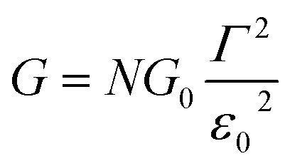 | (3) |
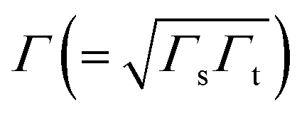 being the geometrical average of the couplings Γs and Γt between the MO and the substrate (s) and tip (t) electrodes, G0 = 2e2/h is the quantum conductance, and N is the number of molecules contributing to the transport through the CP-AFM junction.
In the case of molecular junctions with asymmetric I–V characteristics, the quantity V2/|I|51,55 exhibits two maxima asymmetrically located at biases of opposite polarities (Vt+ > 0, Vt− = −|Vt−| < 0) and different magnitudes (Vt+ ≠ −Vt−) defining two transition voltages. They can be used to estimate the magnitude of the energy offset of the occupied level (ε0 = −|ε0| = EHOMO − EF < 0) that dominates the charge transport and the Stark effect strength γ as follows18,32,55
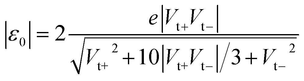 | (4) |
 | (5) |
Low bias resistance R
The measured low bias R-data presented in Table 1, which shows the main results for our CP-AFM junctions, reveal two important aspects. First, R exponentially increases with the molecular size n (cf. Fig. S3A†), in accord with eqn (S5),† wherein the dependencies on size (n) and contact (Rc) are disentangled. This exponential dependence is well known36,40–46 and represents a clear indication of transport via off-resonant tunneling. Second, R (and Rc) dramatically decreases as the electrode work function Φ increases (cf. Fig. S3B†). Given the fact just noted that the transport occurs by tunneling and the fact that transport data are well described within a single level picture (see the section “Self-consistency check: simulation of full I–V curves using the single level” below), this dependence on Φ represents unambiguous evidence that charge transport in CnT junctions is mediated by an occupied level.| Electrodes | Quantity | C7T | C8T | C9T | C10T | C12T |
|---|---|---|---|---|---|---|
| Ag–Ag, β = 1.16, Rc = 3.5 × 10⁴ | R | 6.89 × 10⁷ | 4.20 × 10⁸ | 9.78 × 10⁸ | 3.86 × 10⁹ | 3.65 × 10¹⁰ |
| V t− | 1.26 | 1.23 | 1.22 | 1.20 | 1.21 | |
| V t+ | 1.46 | 1.39 | 1.42 | 1.44 | 1.44 | |
| |ε0| | 1.17 | 1.13 | 1.14 | 1.13 | 1.14 | |
| γ | −0.032 ± 0.008 | −0.026 ± 0.007 | −0.033 ± 0.007 | −0.039 ± 0.01 | −0.038 ± 0.009 | |
| Γ | 1.92 | 0.75 | 0.49 | 0.25 | 0.08 | |
| Au–Au, β = 1.19, Rc = 1.5 × 10³ | R | 6.17 × 10⁶ | 3.14 × 10⁷ | 8.47 × 10⁷ | 3.07 × 10⁸ | 2.85 × 10⁹ |
| V t− | 1.06 | 1.05 | 1.00 | 1.02 | 1.01 | |
| V t+ | 1.28 | 1.31 | 1.22 | 1.25 | 1.29 | |
| |ε0| | 1.01 | 1.01 | 0.95 | 0.97 | 0.98 | |
| γ | −0.041 ± 0.011 | −0.048 ± 0.011 | −0.043 ± 0.015 | −0.044 ± 0.013 | −0.053 ± 0.014 | |
| Γ | 5.50 | 2.45 | 1.41 | 0.75 | 0.25 | |
| Pt–Pt, β = 1.16, Rc = 3.1 × 10² | R | 8.11 × 10⁵ | 4.59 × 10⁶ | 1.17 × 10⁷ | 4.02 × 10⁷ | 4.10 × 10⁸ |
| V t− | 0.94 | 0.93 | 0.91 | 0.86 | 0.88 | |
| V t+ | 1.18 | 1.19 | 1.15 | 1.09 | 1.15 | |
| |ε0| | 0.91 | 0.91 | 0.88 | 0.83 | 0.87 | |
| γ | −0.049 ± 0.008 | −0.053 ± 0.01 | −0.051 ± 0.009 | −0.051 ± 0.01 | −0.058 ± 0.011 | |
| Γ | 13.68 | 5.74 | 3.50 | 1.79 | 0.58 |
General I–V behavior in a nonlinear bias range and transition voltage
Fig. 2A, C and 2E display representative full I–V characteristics of CP-AFM junctions based on CnT (n = 7, 8, 9, 10, 12) with various metallic electrodes (tip, substrate = Ag, Au or Pt). The semilogarithmic I–V traces are shown in Fig. S4.† For a given bias and electrode type, currents decrease exponentially with the length. For a given molecular species (i.e., fixed n) and bias, currents increase as the electrode work function increases. Again, these two features indicate hole transport via tunneling mediated by an occupied level. | ||
| Fig. 2 Representative averaged I–V traces and transition voltage spectra of alkane monothiols CnT (n = 7, 8, 9, 10, 12) embedded in (A, B) Ag/Ag, (C, D) Au/Au, and (E, F) Pt/Pt CP-AFM junctions. | ||
For a more comprehensive examination of transport properties as in our previous study on alkane dithiols,36 we investigated the full I–V characteristics over the interval ±1.6 V (±2.0 V for Ag/Ag junctions), recasting them as curves of V2/|I| versus V (Fig. 2B, D and F). This type of plot exhibits two peaks, which define the (transition) bias (V = Vt) for either bias polarity (Vt → Vt±) where the differential conductance is two times larger than the nominal (pseudo-ohmic) conductance  . This approach is an alternative reformulation of transition voltage spectroscopy (TVS),34 as it can be shown that the voltage at the peak maximum and the transition voltage Vt (defined as the bias at the minimum of the Fowler–Nordheim plot) are mathematically identical.55 In contrast to the symmetric I–V curves of alkane dithiol junctions,33 the I–V curves of the present CnT exhibit a significant asymmetry [I(−V) ≠ −I(V)]. Accordingly, the magnitude of the transition voltages at positive (Vt+ > 0) and negative (Vt− < 0) biases for CnT differs (cf.Table 1). Table 1 and Fig. S5A† show that the average value at positive bias polarity (i.e. the tip in contact with the methyl end is positively polarized with respect to the substrate in contact with the thiol anchoring group) Vt+ is ∼0.2 V larger than the magnitude of the average value |Vt−| at negative bias polarity (i.e. the tip in contact with the methyl ends is negatively polarized with respect to the substrate in contact with the thiol anchoring group).
The experimental values of Vt± and eqn (4) allow us to determine the energy offset of the dominant level |ε0| (see ESI† for details). For a given metal contact, our data show no significant length dependence of Vt (Fig. S5A†), in agreement with previously reported Vt values of alkane monothiols on Au electrodes.56Viaeqn (4), this results in n-independent |ε0|-values (Fig. 3A). On the other hand, the absolute values of Vt± decrease with increasing the work function of the electrodes (see Fig. S5B†). This yields |ε0|-values decreasing with increasing Φ (see Fig. 3B), which is consistent with the fact that charge transport is mediated by an occupied level.
 | ||
| Fig. 3 HOMO energy offset relative to the Fermi level of electrodes for M–CnT–M junctions (M = Ag, Au, Pt; n = 7, 8, 9, 10, 12) as a function of (A) molecular length and (B) bare electrode work function. The lines represent linear fits. | ||
In spite of some statistical spread (see the γ-histograms of Fig. S7†), there is a clear indication that the sign of γ obtained in this way is negative. By virtue of eqn (2), this implies that an electric field pointing toward the methyl group (negatively polarized tip, V < 0) yields an upward shift of the dominant level energy while an electric field pointing toward the thiol group (positively polarized tip, V > 0) yields a downward level shift, as shown in Fig. 4A and B, respectively (see earlier discussion of the sign of γ).
 | ||
| Fig. 4 Energy diagram at (A) negative bias V ≡ Vt − Vs < 0 and (B) positive bias V ≡ Vt − Vs > 0. The negative value of γ of CnT junction yields |ε0(V < 0)| < |ε0(V > 0)|, and thus |I(V < 0)| > |I(V > 0)|. Note that the HOMO level, which is localized near the substrate, appears to track the tip potential, which is opposite to the predictions of the potentiometer framework. We claim that the HOMO shifts under bias are actually due to the Stark effect. | ||
As we will see below, corroborating the information on γ extracted from the measurements with the results of quantum chemical calculations yields important new insight into current rectification. We note for now that the negative value of γ contradicts predictions based on the potentiometer rule as the HOMO, localized on the thiol bonded to the substrate, could be expected to track the substrate potential, whereas the HOMO energy instead appears to track the tip potential (γ < 0 means the HOMO tracks the tip potential).
Self-consistency check: simulation of full I–V curves using the single level model
With the model parameters |ε0|, γ, and Γ determined from the experimental Vt±- and G-values viaeqn (3)–(5) we are able to reproduce well the individual I–V traces measured for CnT junctions. Some representative I–V theoretical curves obtained viaeqn (1) and (2) superimposed on the corresponding measured I–V traces in the bias range (|V| < 1.5|ε0|/e) where eqn (1) applies18 are presented in Fig. 5 and S8.† As visible there, similar to the cases of symmetric I–V curves (γ = 0, Vt+ = −Vt− = Vt),32,33 the agreement between the theory based on the single level model and experiment is also very good for the present case wherein the I–V curves are asymmetric (γ ≠ 0, Vt+ ≠ −Vt−). Noteworthy is the fact that, similar to the case of molecular junctions with symmetric I–V characteristics, to determine our model parameters, we need not fit the full I–V curves; we only fix these model parameters as described above. Of course, the fact that the I–V curves calculated in this way excellently reproduce the experimental curves represents a significant self-consistency check for the model based on the bias-driven shifted single level, thereby validating this model for the benchmark case of molecular (CnT) junctions with asymmetric I–V characteristics. | ||
| Fig. 5 The good agreement between the individual experimental I–V curves (red) for C12T and those obtained theoretically viaeqn (1) (black) is illustrated here for (A) Ag/Ag, (B) Au/Au and (C) Pt/Pt junctions. For each junction, the three parameters needed in eqn (1) – low bias conductance G (1/R), energy offset |ε0| and γ – are indicated in the legends. | ||
To end this part, the presently employed model provides us with a better understanding of the properties of the CP-AFM junctions investigated here than the Simmons model used earlier by our group36 and others43,44 for the same type of junctions.
Important insight into charge transport aided by quantum chemical calculations
The foregoing discussion indicated that the overall increase in currents at both low and higher biases with increasing electrode work function observed in experiments is incompatible with conduction dominated by the LUMO.57 The I–V measurements presented above demonstrated that the charge transport in the present CP-AFM molecular junctions based on alkane monothiols can be explained by assuming that a single occupied level is dominant. On this basis, a LUMO-mediated conduction should be ruled out (for further arguments against LUMO conduction see the discussion related to Fig. S9 in the ESI†). So, a conduction dominated by the closest occupied MO to the metallic Fermi energy (which is the HOMO) appears to be the most plausible assumption. A series of results of ab initio calculations at the OVGF level of theory53,54 using 6-311++g(d,p) basis sets for all atoms will be presented below that reveal similar behaviors of the HOMO energies calculated for isolated CnT molecules and the energies of the occupied level found to dominate the charge transport in CnT-based junctions, thereby supporting the assumption of a HOMO-mediated conduction.| EHOMO,m(V) = EHOMO,m + γmeVm = EHOMO,m − |γm|eVm | (6) |
 | ||
| Fig. 6 Results of quantum chemical OVGF computations for isolated molecules. (A) Schematic representation of the spatial distribution of the HOMO of C10T at zero bias and its changes under the different polarities. Notice that in panel A the picture in the left part shows the HOMO distribution ρHOMO(r, V = 0) computed without bias, while the pictures in the right part show computed changes – which are very small – in the HOMO distributions δρHOMO(r, Vm) ≡ ρHOMO(r, Vm) − ρHOMO(r, V = 0) brought about by biases |Vm| ≈ 1.5 V depicted by using an isovalue representing ∼0.7% of the isovalue employed to depict the HOMO at zero bias (i.e., in the left picture). (B) HOMO energies of isolated alkanethiol molecules CnT (n = 7, 8, 9, 10, 12) as a function of the applied electric field Є. (C) HOMO energies as function of bias Vm between the molecular ends. The slopes of the lines in (C) represent γm < 0. We note that OVGF calculations yield a linear dependence for biases much higher than the V-range of experimental interest shown here. | ||
It is worthwhile noting that an applied field/bias acts as a perturbation on the molecule that in principle may cause corrections to both the HOMO energy (eqn (6)) and HOMO spatial density. From the point of view of quantum mechanics, the HOMO energy is an eigenvalue, and the HOMO spatial distribution is expressed by ρHOMO(r) ≡ |Ψ(r)|2, where its wave function Ψ is an eigenfunction. Quantum mechanics (e.g., ref. 61) tells us that, if corrections to eigenvalues are of first order, corrections to eigenfunctions are negligible (first-order corrections to eigenvalues can be accurately calculated with eigenfunctions of the unperturbed system). The very weak impact of the applied bias on the HOMO spatial distribution is illustrated in Fig. 6A. The left panel of Fig. 6A depicts the HOMO spatial density ρHOMO(r, V = 0) in the absence of bias generated with GABEDIT62 by using an isovalue of 1.3 × 10⁻² a.u. (atomic units). The right panel visualizes changes in the HOMO distribution ρHOMO(r, V ≠ 0) at biases close to the highest values used in experiment. If we depicted those HOMO distributions ρHOMO(r, V = ±1.5 V), their very small differences from the left panel at V = 0 would be invisible within any reasonable drawing accuracy. Therefore, to give a flavor of these tiny changes, in the right panels of Fig. 6A we present changes in the HOMO density δρHOMO(r, V) ≡ ρHOMO(r, V) − ρHOMO(r, V = 0) by using a much smaller isovalue of 9.4 × 10⁻⁵ a.u.
We noted above that the dependence of the HOMO energy (eqn (6)) is found to be linear (i.e., of first order in V). This implies that an applied bias negligibly affects the HOMO wave function. In turn, this means that bias-driven changes to the HOMO spatial density are altogether negligible. For this reason, MO (HOMO or else) spatial distributions are not significantly altered by applied biases in all other cases where quantum chemical calculations yield a linear dependence on the V of the type expressed by eqn (6). In the same vein, improving rectification by a bias-driven enhancement of the asymmetry of MO distributions can hardly be expected.
The linear dependence of the HOMO energy expressed by eqn (6) is analogous to the linear behavior of the energy of the occupied level found to dominate the transport in CnT junctions expressed by eqn (2). Note also that the calculated linear dependence exhibited in Fig. 6 is a direct consequence of the strongly inhomogeneous spatial distribution of the HOMO (see below).
So, as anticipated, the results of quantum chemical calculations presented above support the assumption of a HOMO-mediated conduction in CnT junctions. They reveal a series of similarities between the HOMO energies and the values extracted from transport data of the energies of the single level found to dominate the charge transport, which indicates that it is plausible to ascribe the occupied dominant level to the HOMO. Out of these similarities, the fact that both γm and γ are negative is particularly noteworthy, as it is related to a counterintuitive behavior. According to common intuition, in a molecular junction under applied bias, the dominant energy level follows the “motion” of the Fermi level of the electrode to which it is strongly coupled. A CnT molecule has its HOMO localized on the thiol group (cf.Fig. 6A), very close to the substrate, on which it is chemisorbed. Therefore, one can expect that the HOMO energy will follow the substrate's Fermi energy and not the Fermi energy of the tip, on which the molecule is physisorbed. This behavior would correspond to γ > 0. This would be just opposite to the situation depicted in Fig. 4, which is the picture compatible with the transport measurements. This “intuitive” argument assumes that simple classical electrostatics dictates the behavior of the potential across the junction, smoothly interpolating between the substrate and the tip according to the potentiometer rule. The OVGF results shown here do not support this classical electrostatic description. They emphasize the fact that there is a quantum mechanical contribution to the MO-shifts driven by the electric field;22 rather than a voltage division (potentiometric) factor,17,18γ of eqn (2) (and γm of eqn (6)) represents a Stark effect strength.22 Note that the linear dependence on Є (and on bias) is the direct consequence of the strongly inhomogeneous spatial distribution of the relevant level; the linear contribution in Є would vanish and the correction to the level energy would be proportional to Є2 if the spatial distribution was homogeneous, like in the case of the Stark effect for atoms.61
More quantitatively, one should note that γ of eqn (2) describes the bias-driven shift of the HOMO energy of a molecule embedded in a CP-AFM junction, while γm of eqn (6) refers to the HOMO of an isolated molecule. If we identified the bias Vm with the experimental tip-substrate bias V, the slopes of Fig. 6C (γm) would be almost one order of magnitude larger than the values of γ extracted from experiment (cf.Table 1, Fig. 7A). We interpret this result – and consider it as a key finding of this study – as evidence that the HOMO does not respond to the entire bias (V) applied on the junction; what the HOMO energy feels is only a small fraction q of the bias applied between the tip and the substrate:
 | (7) |
 | ||
| Fig. 7 (A) Stark effect strength γ of M–CnT–M junctions. Within errors (standard deviations δγ are shown here as error bars), the experimental values of γ are independent of the molecular size n. (values of γ and δγ are from Table 1). (B) The bias Vm felt by the HOMO only represents a small fraction q (depicted in this panel) from the total bias V applied between the tip and the substrate. Here q = Vm/V = γ/γm where γ comes from panel (a) (i.e., experiment) and γm is the result of calculations (see Fig. 6C). (C) Computed rectification ratio RR ≡ −I(−V)/I(V) for several values of the Stark effect strength γ ranging from the experimental value (γ ≈ −0.05, cf.Table 1) and the theoretical OVGF value (γ ≈ −0.3). | ||
This ratio q is represented in Fig. 7B. As already noted, the values q ≈ 0.1–0.15 visible in Fig. 7B indicate that only a small amount of the applied bias (10–15%) is felt by the HOMO. This necessarily implies that, at least for the presently considered molecular junctions based on alkanethiols, the contacts are far from optimal; they substantially mitigate the effect of the applied bias on the HOMO energy of the embedded molecules.
Recently, various groups succeeded in fabricating molecular devices exhibiting rectification ratios (RRs) larger than 102 or even 105.12–15,23,24,63–68 In view of such achievements, it is hard to discuss “rectification” based on the very modest values RR ≈ 1.5 that characterize CnT junctions. However – and this is the important point we want to make here – these small RR-values are merely a consequence of the fact that the HOMO of CnT does not respond to the entire substrate-tip bias. Within the bias-driven single level model – which turned out to be successful in describing the presently analyzed I–V asymmetry (“rectification”) – current rectification is very sensitive to the values of γ (RR = 1 for γ = 0). To illustrate this point, in Fig. 7C we present curves for rectification at biases accessed in experiments and values of γ ranging from γ = −0.05 to γ = −0.3; where, the lowest γ-value corresponds to the experimental situation (cf.Table 1) while the latter value represents an average of the theoretical γ-values obtained within OVGF calculations. The message conveyed by Fig. 7C should be clear: rectifications RR ≈ 500 (see the curve for γ = −0.3) comparable to reasonably high values reported in the literature can be reached if improved contact engineering made it possible that the active HOMO level would feel the entire applied bias.
From the foregoing perspective, identifying and implementing appropriate electrically transparent contacts (no screening) appears to be an important problem for molecular rectification. In this vein, it is not at all surprising that significant improvements of molecular rectifiers were obtained with non-traditional approaches of contacting the SAM to electrodes. Attempting to employ platforms wherein covalent coupling between the electrode and the “active” unit (thiol in our case) on which the dominant HOMO orbital is centered is replaced by non-covalent interactions (e.g., van der Waals interactions) seems to be a meaningful route to pursue in view of the recent rectification improvements achieved in this way (the weak coupling regime).14,45,69
Conclusion
In this paper, we have reported results of a joint experimental–theoretical investigation of the transport properties of CP-AFM molecular junctions based on alkane monothiols (CnT) of various lengths n and metallic electrodes (Ag, Au, and Pt) having work functions Φ varying within a broad range of ∼1.4 eV. An important aspect of the present study, which enables us to propose a coherent picture of the transport, is the validation of the model of a single dominant level that is linearly shifted by the applied bias (linear Stark effect as opposed to quadratic Stark effect in atoms).Contrary to what one expects intuitively based on the potentiometer rule, CnT junctions exhibit very modest rectification ratios (RR ≈ 1.5). By corroborating the experimental results on nanojunctions with state-of-the art ab initio quantum chemical calculations based on the outer valence Green's function (OVGF) method for isolated molecules, we are able to understand why this rectification is so unexpectedly weak. Namely, we have demonstrated that it is only a small fraction of the applied voltage that is responsible for the bias driven shift of the dominant level energy, which in turn is responsible for current rectification. This is a clear indication that phenomena occurring at molecule–electrode contacts are responsible for the unexpected weak rectification of CnT junctions. We believe that this finding represents an important new insight into the role played by contacts in mitigating the impact of the applied bias on the embedded molecule (possibly via interface states), which is an essential point to consider for improving the performance of molecular rectifiers.
Experimental section
Materials
1-Heptanethiol (C7T) 98%, 1-octanethiol (C8T) 98.5%, 1-nonanethiol (C9T) 99%,1-decanethiol (C10T) 99%, and 1-dodecanethiol (C12T) 98% were purchased from Sigma Aldrich. Gold nuggets (99.999% pure) were purchased from Mowrey, Inc. (St. Paul, MN). Silver pellets (99.99% pure) were purchased from Kurt J. Lesker Company. Evaporation boats and chromium evaporation rods were purchased from R. D. Mathis (Long Beach, CA). Platinum and titanium for e-beam evaporation were purchased from Kamis, Inc. (Mahopac Falls, NY). Silicon (100) wafers were obtained from WaferNet (San Jose, CA). Contact mode AFM tips (DNP-10 silicon nitride probes) were purchased from Bruker AFM Probes.Conducting tip and sample preparation
Contact mode AFM tips were coated with Ag, Au and Pt. Template-stripped flat metal substrates were used to grow high quality self-assembled monolayers (SAMs) for sample characterization and reproducible electrical measurements. The preparation of AFM tips and template stripped flat substrates with Ag, Au and Pt has been described previously.70,71 SAMs were formed by immersing clean template-stripped flat metal substrates in ethanol solution of molecules at a concentration of 1–2 mM for 20 h. Afterward, the samples were rinsed with ethanol and dried with flowing N2.Transport measurements
The electrical measurements were completed by mounting the substrates in the AFM and bringing the metal coated tip into contact with the SAM under ∼1 nN of applied compressive load, Fig. 1A. The voltages were applied to the tip with a Keithley model 236 electrometer operated in “DC mode”. Voltage was swept at the tip, and I–V characteristics were recorded; V > 0 means a positive tip (electric field pointing to the thiol/substrate, cf.Fig. 4). All measured I–V curves were linear at low biases and nonlinear at higher biases. The inverse slope of the linear portion of the I–V characteristics was employed to define a junction (ohmic) resistance. The low bias resistance was measured between ±0.1 V except the data of C12T, which were collected between ±0.5 V due its low conductivity, and ±1.5–2 V was applied to the tip to get the transition voltage Vt.Theory section
Quantum chemical calculations
The quantum chemical calculations were based on the OVGF method.53,54 For the medium-size molecular species in external electric fields considered in this study, the OVGF method represents the state-of-the-art quantum chemistry. This method was successfully applied to molecular species and sizes of interest for molecular electronics in several recent studies72–74 wherein effects of an external field were not considered. OVGF calculations were done using the implementation in the GAUSSIAN 09 suite of programs,75 as it allows calculations with external fields. OVGF calculations using GAUSSIAN 09 in an external electric field can be done by appropriately setting the relevant keywords. To exemplify, in the case of an external field of 8 GAUSSIAN units (1 GAUSSIAN unit = 10−4 a.u. = 0.05142 V nm−1) along the negative y axis, we set “FIELD = Y-8 NoSymm EPT = OVGF TRAN = FULL IOP(9/11 = 100)” in the GAUSSIAN*.com input file. Within the OVGF framework the HOMO energies (shown in Fig. 6) are estimated from the poles of the one-particle Green's function. The HOMO energy represents the lowest ionization energy with reversed sign.Conflicts of interest
There are no conflicts to declare.Acknowledgements
C. D. F. acknowledges financial support from the U.S. National Science Foundation (CHE-1708173). I. B. acknowledges financial support from the Deutsche Forschungsgemeinschaft (DFG grant BA 1799/3-1) and computational support by the State of Baden-Württemberg through bwHPC and the Deutsche Forschungsgemeinschaft (DFG) through grant no. INST 40/467-1 FUGG.76References
- N. J. Tao, Nat. Nanotechnol., 2006, 1, 173–181 CrossRef CAS PubMed.
- X. Guo, J. P. Small, J. E. Klare, Y. Wang, M. S. Purewal, I. W. Tam, B. H. Hong, R. Caldwell, L. Huang, S. O'Brien, J. Yan, R. Breslow, S. J. Wind, J. Hone, P. Kim and C. Nuckolls, Science, 2006, 311, 356–359 CrossRef CAS PubMed.
- F. Meng, Y.-M. Hervault, Q. Shao, B. Hu, L. Norel, S. Rigaut and X. Chen, Nat. Commun., 2014, 5, 3023 Search PubMed.
- C. Jia, A. Migliore, N. Xin, S. Huang, J. Wang, Q. Yang, S. Wang, H. Chen, D. Wang, B. Feng, Z. Liu, G. Zhang, D.-H. Qu, H. Tian, M. A. Ratner, H. Q. Xu, A. Nitzan and X. Guo, Science, 2016, 352, 1443–1445 CrossRef CAS PubMed.
- R. Hayakawa, M. A. Karimi, J. Wolf, T. Huhn, M. S. Zöllner, C. Herrmann and E. Scheer, Nano Lett., 2016, 16, 4960–4967 CrossRef CAS PubMed.
- R. Naaman and D. H. Waldeck, Annu. Rev. Phys. Chem., 2015, 66, 263–281 CrossRef CAS PubMed.
- T. A. Su, H. Li, M. L. Steigerwald, L. Venkataraman and C. Nuckolls, Nat. Chem., 2015, 7, 215–220 CrossRef CAS PubMed.
- A. C. Aragones, D. Aravena, J. I. Cerda, Z. Acís-Castillo, H. Li, J. A. Real, F. Sanz, J. Hihath, E. Ruiz and I. Díez-Pérez, Nano Lett., 2015, 16, 218–226 CrossRef PubMed.
- A. M. Najarian, B. Szeto, U. M. Tefashe and R. L. Mccreery, ACS Nano, 2016, 10, 8918–8928 CrossRef PubMed.
- A. C. Aragonès, N. L. Haworth, N. Darwish, S. Ciampi, N. J. Bloomfield, G. G. Wallace, I. Diez-Perez and M. L. Coote, Nature, 2016, 531, 88–91 CrossRef PubMed.
- L. Sepunaru, S. Refaely-Abramson, R. Lovrinčić, Y. Gavrilov, P. Agrawal, Y. Levy, L. Kronik, I. Pecht, M. Sheves and D. Cahen, J. Am. Chem. Soc., 2015, 137, 9617–9626 CrossRef CAS PubMed.
- W. Lo, N. Zhang, Z. Cai, L. Li and L. Yu, Acc. Chem. Res., 2016, 49, 1852–1863 CrossRef CAS PubMed.
- D. Xiang, X. Wang, C. Jia, T. Lee and X. Guo, Chem. Rev., 2016, 116, 4318–4440 CrossRef CAS PubMed.
- L. Yuan, N. Nerngchamnong, L. Cao, H. Hamoudi, E. del Barco, M. Roemer, R. K. Sriramula, D. Thompson and C. A. Nijhuis, Nat. Commun., 2015, 6, 6324 CrossRef CAS PubMed.
- Q. Van Nguyen, P. Martin, D. Frath, M. L. Della Rocca, F. Lafolet, P. Lafarge, V. Mukundan, D. James, R. L. Mccreery and J. Lacroix, J. Am. Chem. Soc., 2017, 139, 11913–11922 CrossRef PubMed.
- A. Aviram and M. A. Ratner, Chem. Phys. Lett., 1974, 29, 277–283 CrossRef CAS.
- F. Zahid, M. Paulsson and S. Datta, Electrical conduction through molecules, in Advanced semiconductors and organic nano-techniques, Academic Press, New York, 2003, vol. 3, chapter electrical conduction through molecules Search PubMed.
- I. Bâldea, Phys. Rev. B: Condens. Matter Mater. Phys., 2012, 85, 35442 CrossRef.
- A. R. Garrigues, L. Yuan, L. Wang, E. R. Mucciolo, D. Thompon, E. del Barco and C. A. Nijhuis, Sci. Rep., 2016, 6, 26517 CrossRef CAS PubMed.
- N. Zhang, W. Y. Lo, Z. Cai, L. Li and L. Yu, Nano Lett., 2017, 17, 308–312 CrossRef CAS PubMed.
- G. Zhang, M. A. Ratner and M. G. Reuter, J. Phys. Chem. C, 2015, 119, 6254–6260 CAS.
- I. Bâldea, Phys. Chem. Chem. Phys., 2015, 17, 31260–31269 RSC.
- X. Chen, M. Roemer, L. Yuan, W. Du, D. Thompson, E. Barco and C. A. Nijhuis, Nat. Nanotechnol., 2017, 12, 797–803 CrossRef CAS PubMed.
- R. M. Metzger, Chem. Rev., 2015, 115, 5056–5115 CrossRef CAS PubMed.
- C. A. Nijhuis, W. F. Reus and G. M. Whitesides, J. Am. Chem. Soc., 2009, 131, 17814–17827 CrossRef CAS PubMed.
- D. J. Wold and C. D. Frisbie, J. Am. Chem. Soc., 2000, 122, 2970–2971 CrossRef CAS.
- S. H. Choi, B. Kim and C. D. Frisbie, Science, 2008, 320, 1482–1486 CrossRef CAS PubMed.
- C. Nogues, S. R. Cohen, S. S. Daube and R. Naaman, Phys. Chem. Chem. Phys., 2004, 6, 4459–4466 RSC.
- G. Ricœur, S. Lenfant, D. Guérin and D. Vuillaume, J. Phys. Chem. C, 2012, 116, 20722–20730 Search PubMed.
- G. Wang, T.-W. Kim, G. Jo and T. Lee, J. Am. Chem. Soc., 2009, 131, 5980–5985 CrossRef CAS PubMed.
- H. Song, H. Lee and T. Lee, J. Am. Chem. Soc., 2007, 129, 3806–3807 CrossRef CAS PubMed.
- Z. Xie, I. Bâldea, C. E. Smith, Y. Wu and C. D. Frisbie, ACS Nano, 2015, 9, 8022–8036 CrossRef CAS PubMed.
- Z. Xie, I. Bâldea, S. Oram, C. E. Smith and C. D. Frisbie, ACS Nano, 2017, 11, 569–578 CrossRef CAS PubMed.
- J. M. Beebe, B. Kim, J. W. Gadzuk, C. D. Frisbie and J. G. Kushmerick, Phys. Rev. Lett., 2006, 97, 26801 CrossRef PubMed.
- I. Bâldea, J. Am. Chem. Soc., 2012, 134, 7958–7962 CrossRef PubMed.
- V. B. Engelkes, J. M. Beebe and C. D. Frisbie, J. Am. Chem. Soc., 2004, 126, 14287–14296 CrossRef CAS PubMed.
- S. Guo, J. Hihath, I. Díez-Pérez and N. J. Tao, J. Am. Chem. Soc., 2011, 133, 19189–19197 CrossRef CAS PubMed.
- C. Li, I. Pobelov, T. Wandlowski, A. Bagrets, A. Arnold and F. Evers, J. Am. Chem. Soc., 2008, 130, 318–326 CrossRef CAS PubMed.
- W. Lee and P. Reddy, Nanotechnology, 2011, 22, 485703 CrossRef PubMed.
- M. M. Thuo, W. F. Reus, C. A. Nijhuis, J. R. Barber, C. Kim, M. D. Schulz and G. M. Whitesides, J. Am. Chem. Soc., 2011, 133, 2962–2975 CrossRef CAS PubMed.
- R. E. Holmlin, R. Haag, M. L. Chabinyc, R. F. Ismagilov, A. E. Cohen, A. Terfort, M. A. Rampi and G. M. Whitesides, J. Am. Chem. Soc., 2001, 123, 5075–5085 CrossRef CAS PubMed.
- F. Chen, X. Li, J. Hihath, Z. Huang and N. Tao, J. Am. Chem. Soc., 2006, 128, 15874–15881 CrossRef CAS PubMed.
- W. Wang, T. Lee and M. A. Reed, Phys. Rev. B: Condens. Matter Mater. Phys., 2003, 68, 35416 CrossRef.
- X. D. Cui, X. Zarate, J. Tomfohr, O. F. Sankey, A. Primak, A. L. Moore, T. A. Moore, D. Gust, G. Harris and S. M. Lindsay, Nanotechnology, 2002, 13, 5–14 CrossRef CAS.
- C. S. S. Sangeeth, A. Wan and C. A. Nijhuis, J. Am. Chem. Soc., 2014, 136, 11134–11144 CrossRef CAS PubMed.
- H. J. Yoon, C. M. Bowers, M. Baghbanzadeh and G. M. Whitesides, J. Am. Chem. Soc., 2014, 136, 16–19 CrossRef CAS PubMed.
- C. Boulas, J. V. Davidovits, F. Rondelez and D. Vuillaume, Phys. Rev. Lett., 1996, 76, 4797–4800 CrossRef CAS PubMed.
- X. D. Cui, A. Primak, X. Zarate, J. Tomfohr, O. F. Sankey, A. L. Moore, T. a. Moore, D. Gust, G. Harris and S. M. Lindsay, Science, 2001, 294, 571–574 CrossRef CAS PubMed.
- H. Song, Y. Kim, Y. H. Jang, H. Jeong, M. A. Reed and T. Lee, Nature, 2009, 462, 1039–1043 CrossRef CAS PubMed.
- A. Salomon, D. Cahen, S. Lindsay, J. Tomfohr, V. B. Engelkes and C. D. Frisbie, Adv. Mater., 2003, 15, 1881–1890 CrossRef CAS.
- I. Bâldea, Z. Xie and C. D. Frisbie, Nanoscale, 2015, 7, 10465–10471 RSC.
- C. Guo, X. Yu, S. Refaely-Abramson, L. Sepunaru, T. Bendikov, I. Pecht, L. Kronik, A. Vilan, M. Sheves and D. Cahen, Proc. Natl. Acad. Sci. U. S. A., 2016, 113, 10785–10790 CrossRef CAS PubMed.
- L. S. Cederbaum, J. Phys. B: At. Mol. Phys., 1975, 8, 290–303 CrossRef CAS.
- W. van Niessen, J. Schirmer and L. S. Cederbaum, Comp. Phys. Rep., 1984, 1, 57–125 CrossRef.
- I. Bâldea, Phys. Chem. Chem. Phys., 2015, 17, 20217–20230 RSC.
- G. Ricoeur, S. Lenfant, D. Guérin and D. Vuillaume, J. Phys. Chem. C, 2012, 116, 20722–20730 Search PubMed.
- Y. Qi, O. Yaffe, E. Tirosh, A. Vilan, D. Cahen and A. Kahn, Chem. Phys. Lett., 2011, 511, 344–347 CrossRef CAS.
- D. M. Alloway, M. Hofmann, D. L. Smith, N. E. Gruhn, A. L. Graham, R. Colorado, V. H. Wysocki, T. R. Lee, P. A. Lee and N. R. Armstrong, J. Phys. Chem. B, 2003, 107, 11690–11699 CrossRef CAS.
- D. M. Alloway, A. L. Graham, X. Yang, A. Mudalige, R. Colorado, V. H. Wysocki, J. E. Pemberton, T. R. Lee, R. J. Wysocki and N. R. Armstrong, J. Phys. Chem. C, 2009, 113, 20328–20334 CAS.
- M. Baghbanzadeh, C. M. Bowers, D. Rappoport, T. Żaba, L. Yuan, K. Kang, K. C. Liao, M. Gonidec, P. Rothemund, P. Cyganik, A. Aspuru-Guzik and G. M. Whitesides, J. Am. Chem. Soc., 2017, 139, 7624–7631 CrossRef CAS PubMed.
- L. D. Landau and E. M. Lifshtz, Quantum Mechanics (Nonrelativistic Theory), Pergamon Press, 3rd edn, 1977 Search PubMed.
- A. Allouche, J. Comput. Chem., 2011, 32, 174–182 CrossRef CAS PubMed.
- L. Yuan, R. Breuer, L. Jiang, M. Schmittel and C. A. Nijhuis, Nano Lett., 2015, 15, 5506–5512 CrossRef CAS PubMed.
- M. Souto, L. Yuan, D. C. Morales, L. Jiang, I. Ratera, C. A. Nijhuis and J. Veciana, J. Am. Chem. Soc., 2017, 139, 4262–4265 CrossRef CAS PubMed.
- I. Díez-Pérez, J. Hihath, Y. Lee, L. Yu, L. Adamska, M. A. Kozhushner, I. I. Oleynik and N. J. Tao, Nat. Chem., 2009, 1, 635–641 CrossRef PubMed.
- J. Hihath, C. Bruot, H. Nakamura, Y. Asai, I. Díez-Pérez, Y. Lee, L. Yu and N. J. Tao, ACS Nano, 2011, 5, 8331–8339 CrossRef CAS PubMed.
- A. Bayat, J.-C. Lacroix and R. L. McCreery, J. Am. Chem. Soc., 2016, 138, 12287–12296 CrossRef CAS PubMed.
- B. Capozzi, J. Xia, O. Adak, E. J. Dell, Z.-F. Liu, J. C. Taylor, J. B. Neaton, L. M. Campos and L. Venkataraman, Nat. Nanotechnol., 2015, 10, 522–527 CrossRef CAS PubMed.
- A. Wan, C. S. S. Sangeeth, L. Wang, L. Yuan, L. Jiang and C. A. Nijhuis, Nanoscale, 2015, 7, 19547–19556 RSC.
- V. B. Engelkes, J. M. Beebe and C. D. Frisbie, J. Phys. Chem. B, 2005, 109, 16801–16810 CrossRef CAS PubMed.
- B. Kim, S. H. Choi, X.-Y. Zhu and C. D. Frisbie, J. Am. Chem. Soc., 2011, 133, 19864–19877 CrossRef CAS PubMed.
- S. Klaiman, E. V. Gromov and L. S. Cederbaum, J. Phys. Chem. Lett., 2013, 4, 3319–3324 CrossRef CAS.
- V. G. Zakrzewski, O. Dolgounitcheva and J. V Ortiz, J. Phys. Chem. A, 2014, 118, 7424–7429 CrossRef CAS PubMed.
- I. Bâldea, Faraday Discuss., 2014, 174, 37–56 Search PubMed.
- M. J. Frisch, G. W. Trucks, H. B. Schlegel, G. E. Scuseria, M. A. Robb, J. R. Cheeseman, G. Scalmani, V. Barone, B. Mennucci, G. A. Petersson, H. Nakatsuji, M. Caricato, X. Li, H. P. Hratchian, A. F. Izmaylov, J. Bloino, G. Zheng, J. L. Sonnenberg, M. Hada, M. Ehara, K. Toyota, R. Fukuda, J. Hasegawa, M. Ishida, T. Nakajima, Y. Honda, O. Kitao, H. Nakai, T. Vreven, J. A. Montgomery Jr, J. E. Peralta, F. Ogliaro, M. Bearpark, J. J. Heyd, E. Brothers, K. N. Kudin, V. N. Staroverov, T. Keith, R. Kobayashi, J. Normand, K. Raghavachari, A. Rendell, J. C. Burant, S. S. Iyengar, J. Tomasi, M. Cossi, N. Rega, J. M. Millam, M. Klene, J. E. Knox, J. B. Cross, V. Bakken, C. Adamo, J. Jaramillo, R. Gomperts, R. E. Stratmann, O. Yazyev, A. J. Austin, R. Cammi, C. Pomelli, J. W. Ochterski, R. L. Martin, K. Morokuma, V. G. Zakrzewski, G. A. Voth, P. Salvador, J. J. Dannenberg, S. Dapprich, A. D. Daniels, O. Farkas, J. B. Foresman, J. V. Ortiz, J. Cioslowski and D. J. Fox, Gaussian 09, Revision B.01, Gaussian, Gaussian, Inc., Wallingford CT, 2010 Search PubMed.
- bwHPC and bwHPC-C5 (http://www.bwhpc-c5.de) funded by the Ministry of Science, Research and the Arts Baden–Württemberg, the Universities of the State Baden–Württemberg, and the German Research Foundation (DFG).
Footnotes |
| † Electronic supplementary information (ESI) available: Experimental and theoretical details, supplementary figures. See DOI: 10.1039/c8sc00938d |
| ‡ Equal contribution. |
| This journal is © The Royal Society of Chemistry 2018 |