Flow synthesis of coumalic acid and its derivatization†
Laura K.
Smith
 and
Ian R.
Baxendale
 *
*
Department of Chemistry, University of Durham, South Road, Durham, DH1 3LE, UK. E-mail: i.r.baxendale@dur.ac.uk; Tel: +(0)44 191 334 2185
First published on 20th July 2018
Abstract
Coumalic acid is a valuable platform compound which can be prepared from malic acid, a biorenewable feedstock readily derived from the fermentation of glucose. Current batch procedures to synthesise coumalic acid have several drawbacks, which we address with the aid of tubular flow systems and a simple heated rotating flow reactor. The prepared coumalate derivatives can be further used in inverse electron demand Diels–Alder reactions to synthesise compounds with many applications including molecular electronics, with the added advantage of providing metal-free preparations.
Introduction
Molecular electronics is a branch of nanotechnology that uses single molecules as components in electronic circuits, and numerous reviews have been written on the subject.1 These molecular materials include conductive polymers and molecular salts. One important family of molecules with wide ranging applications as molecular electronic components including in the area of organic light-emitting diodes (OLEDs) is the terphenyls.2A critical consideration in the syntheses of such molecules is their purity, as even low levels of contamination (ppb) can have a significant impact on their properties. This is particularly true of residual heavy metal contamination. However, traditional syntheses of such compounds inevitably rely on nickel- or palladium-catalysed coupling reactions.1 As an intriguing alternative metal-free approach, an inverse electron demand Diels–Alder reaction between an electron-poor coumalic acid derivative as the diene component, partnered with suitable electron-rich alkyne dienophiles (Fig. 1) presents many opertunities.3–12 To progress this approach at meaningful scales consistent with the requirements of the end product production we needed access to large quantities of the coumalic acid derivative starting material.
 | ||
| Fig. 1 Retrosynthetic analysis, showing the substrates for the inverse electron demand Diels–Alder reaction between alkyl coumalates and a suitable dienophile. | ||
Coumalates are platform molecules with a wide range of applications: they are used in the flavours, fragrances and cosmetics industries, as polymer components, and as pharmaceutical scaffolds displaying anti-bronchial and -malarial activity. There exist several literature-reported procedures for the synthesis of the parent coumalic acid.14–21 In this respect, the U.S. Department of Energy has named coumalic acid one of ‘The Top Ten Value Added Chemicals derived from Biomass’, indicating its general importance.22 The most common precursor to coumalic acid is malic acid, a low cost, biorenewable feedstock obtained through the fermentation of glucose (Fig. 2). Likewise the corresponding alkyne substrates can be readily accessed at an industrial scale by simple dehydrogenation of the corresponding styrene or alkane precursors23–30 which although currently are most often sourced from petrochemical feedstocks are increasingly being derived from bio-feeds.31–33 Such consideration gives additional merit to a future production route originating from these starting materials.
 | ||
| Fig. 2 The biorenewable feedstock, malic acid, derived from glucose, and its dimerised condensation product coumalic acid. | ||
Historical context: syntheses of coumalic acid and derivatives
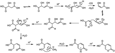
The earliest documented synthesis of coumalic acid was published by von Pechmann in 1891 starting from malic acid.14 A mixture of concentrated sulfuric acid (97–98%) and fuming sulfuric acid was used at 70 °C to effect conversion to coumalic acid, in a reported 70% yield. Caldwell et al. reproduced the same reaction in 1944,20 and later in 1963, Wiley et al. conducted the reaction on a 100 g scale, using the same von Pechmann conditions (Scheme 1).15 Several other groups have subsequently used this transformation with slight modifications to the protocol and changes in scale but without significant impact on the derived yield or throughput.17,19,21Interestingly, it wasn't until 2003 that the mechanism of this reaction was thoroughly investigated by researchers at AstraZeneca Process R&D.16 They found it proceeded via an acid-catalysed dehydration/decarbonylation of malic acid to give an initial aldehyde acid enol which condenses by Michael addition of the enol to the enone, followed by lactonisation and dehydration to give the desired coumalic acid (Scheme 2). Overall, 2 moles of malic acid condense to give a molecule of coumalic acid with the loss of 2 moles of CO and 4 equivalents of water. Indeed, the evolution of carbon monoxide as the only gaseous product was confirmed by gas chromatography–mass spectrometry in our preliminary safety assessment of the reaction which is in full agreement with the proposal of Ashworth et al.16
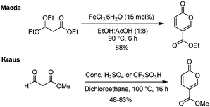
The most recent innovations regarding coumalic acid preparation have come from the work of Kraus et al. who have shown that the addition of a solvent to the system enables processing of malic acid in high conversions using either concentrated H2SO4 or triflic acid (Scheme 3).6,13 In our experience we found this protocol worked well at small scale as reported when very effective mixing was used but we encountered many challenges when these conditions were attempted at larger scales, resulting in much lower yields and higher proportions of (2E)-butenedioic acid.
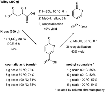
Furthermore, although coumalic acid is a valuable starting material for many synthetic applications its poor solubility restricts its use, and more commonly the corresponding ester is used as a more amenable starting point. Coumalic acid can be methylated by esterification to give the corresponding methyl coumalate. Several groups have attempted this, as exemplified by the work of Boyer et al. in 1956.34 They used MeOH and H2SO4 to achieve a 32–45% isolated yield of the corresponding methyl coumalate (Scheme 4).
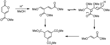
Upon initial inspection this yield appears to be rather low for an apparently simple esterification. However, Ashworth et al. also experienced difficulties with this procedure, especially at scale, noting that under the reaction conditions the methyl coumalate was found to be unstable and underwent decomposition and reorganisation to the alternative aromatic species as shown in Scheme 5.
To circumvent this issue Ashworth et al. instead prepared the desired ester via either an intermediate acid chloride or mixed anhydride followed by reaction with MeOH.16 However, from a consideration of the processing practicality and ease of scaling it was alternatively found that esterification could also be achieved and in a higher yield (65%) by first deprotonating the coumalic acid using a mixture of N,N-diisopropylethylamine in NMP and then reacting the resultant coumalate anion with dimethyl sulfate.
There have also been some attempts by first the groups of Maeda18 and then of Kraus13 to also employ surrogate starting materials such as ethyl 3,3-diethylpropionate and methyl 3-oxo-propionate to direct ester products (Scheme 6). Whereas Kraus relied on the standard acid-catalysed process, Maeda screened a series of Lewis acid catalysts, with the most effective being FeCl3·6H2O. Interestingly, they observed the accompanying formation of triethyl 1,3,5-benzenetricarboxylate as a minor side-product in several of their reactions.
Although these latter condensations of the alkyl 3-oxo-propionate offer high yields in a direct transformation, the preparation of these small fragment starting materials themselves is not a trivial matter.35,36 Indeed, based upon accessibility of reactants and associated cost, the two-step sequence starting from malic acid is still the obvious route of choice. Table 1 presents a summary of the main synthetic work in this area which shows that despite the successive works by several groups, improvements in yield and productivity have been limited. If coumalic acid is to become a viable commodity platform chemical, production throughput needs to be dramatically upgraded.
| Synthesis | Scale/g | Yield | Throughput g h−1 |
|---|---|---|---|
| a No reaction time given. | |||
| von Pechmann 1891 (ref. 14) | 1000 | 80% | 200 |
| Wiley 1963 (ref. 15) | 100 | 65–70% | 17.6 |
| Engel 1973 (ref. 21) | 50 | 81% | |
| Rosenmund 1990 (ref. 19) | 268 | 85% | 13.2 |
| Ashworth 2003 (ref. 16) | 200 | 65% | 11.8 |
| Kaminski 2008 (ref. 17) | 200 | 67% | 6.7 |
| Kraus 2014 (ref. 13) | 5 | 80–86% | 0.13 |
With a desire to access larger quantities of coumalic acid as an intermediate for the preparation of terphenylates for application in the microelectronic industry we were required to evaluate the processing and safety requirements of a new processing sequence. Firstly, in order to increase productivity, several challenges pertaining to the physical processing of material needed to be overcome: firstly, the high viscosity of the sulfuric acid which causes mixing difficulties, and secondly, gas formation (CO) during the reaction which leads to significant foaming. The reaction conditions are also relatively harsh, requiring heating at high temperature for several hours. Finally, the reaction is overall low-yielding as a two-step sequence to generate the corresponding coumalic ester which needed addressing.
Results and discussion
Herein we present a series of improved preparations of methyl coumalate for its production at scale through the development of continuous flow processes including the prototyping of a simple heated tube reactor.Initial batch synthesis of methyl coumalate
We commenced our investigation by first attempting to replicate the original Wiley-described batch procedure to synthesise coumalic acid,15 followed by direct methylation of the unisolated intermediate coumalic acid as a one-pot procedure. The reaction was performed on 200 g of malic acid. The resultant methyl coumalate was of very poor quality, and required several recrystallisations from methanol to obtain the pure product albeit in a low final 40% yield (Scheme 7). This was however consistent with the previously reported yield by Wiley of 65–70% which was quoted prior to recrystallisation.Next, we evaluated the modified conditions reported by Kraus6 again using 200 g of malic acid. This necessitated a 3 L volume of DCE and 397.6 g of sulfuric acid (98%, 5 equiv.) to maintain the proportions of reagents in a direct scale up of the published procedure. The mixture was slowly warmed and heated to reflux (note: a reaction temperature of 100 °C was applied at small scale). Periodic sampling indicated the reaction had reached completion after 8 h, and therefore an aliquot was removed, quenched and worked-up allowing isolation of crude coumalic acid in 67% yield as a tan-coloured powder. The remaining reaction mixture was diluted with MeOH (300 mL) and heated at 80 °C for a further 8 h. Following the literature work-up protocol, crude methyl coumalate was isolated in 57% yield (∼85% purity) and 43% yield following recrystallisation from MeOH (Scheme 7). For quantification purposes we also repeated the sequences on 1 g and 5 g scales of malic acid utilising open flasks (reflux) and sealed microwave vials to enable a reaction temperature of 100 °C to be attained. In these experiments we found the yields were essentially identical between open and closed vessels but higher isolated yields of the final products could be attained. We attribute this to the efficiency of quenching and extraction as part of the work-up protocols at these small scales.
Small-scale flow synthesis of coumalic acid
Having evaluated the most promising batch procedures and established a target yield range we next turned our attention to potentially improving the processing by performing the reaction under flow conditions.37–45 Due to the need for the additional solvent in the Kraus procedure and the lack of any meaningful advantage offered over the Wiley process in terms of yield or work-up we focussed on the latter as the most direct starting point.Initial scoping and optimisation experiments were carried out using a Vapourtec E-Series MedChem reactor system coupled with a Masterflex L/S external peristaltic pump with Masterflex C-Series tubing (size 13). Stock solutions were prepared at a concentration of 100 g malic acid per 200 mL of concentrated H2SO4 (3.73 mol dm−3; 4.93 equiv.) and warmed to 40 °C for 30 min immediately prior to reaction to ensure all malic acid had fully dissolved (note: no indication of reaction at this temperature was observed even after 5 h). A systematic programme of investigation regarding the effects of reactor volumes (residence times), concentration of the stock solution, system pressure, flow rate and reaction temperature on the first stage of conversion of malic acid to coumalic acid was then undertaken.
Three different reactor volumes were evaluated: 10, 20, and 50 mL, with the reaction performed at 0.3 mL min−1 and 70 °C ensuring incomplete conversion. The configuration of combining two 10 mL reactors gave the best and most consistent results (Fig. 3).
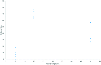 | ||
| Fig. 3 Reactor length plotted against % conversion to coumalic acid (assessed by 1H NMR spectroscopy). Reactions were performed at 70 °C. | ||
On initial inspection the effect of changing the reactor volume appears inconsistent but is mainly due to gas evolution during the reaction which leads to significant slug flow, with segmentation of the liquid phase by large gaseous partitions. This has the effect of propelling the reactant solution through the reactor coil at an accelerated pace resulting in reduced residence times. As can be seen, the use of a single 10 mL (1 mm inner diameter tubing) reactor resulted in very low conversions associated with very unstable flow and inconsistent conversion. Appending a second 10 mL reactor in series stabilises the system (higher pressure drop) creating a more defined flow with more consistent residence times and conversions. The result for the larger 50 mL reactor emphasises the effect as the flow coil is constructed from larger diameter tubing (6 mm i.d.). This reduces the internal pressure drop as well as decreasing mixing, again leading to more phase separation, erratic flow and lower, inconsistent conversion.
A simple solution considered was adding an in-line back-pressure regulator (variable) to the exit of the reactor. However, this had a decidedly negative impact on conversion indicating that gas release was an important factor in the successful reaction. Interestingly, as observed under batch conditions, reactions that exhibited more rapid gas evolution and foaming also correlated well with faster reaction times and improved isolated yields. As there was no beneficial relationship between applied pressure and conversion, we elected to run all further reactions without pressure induction (i.e. an in-line BPR or restrictor valve). We note that the installation of an in-line tube-in-tube reactor46–49 allowing constant removal of the generated gas may be beneficial in this scenario but was not tested in this phase of the work.
The parameter of flow rate was next investigated. The in-built peristaltic pumps of the Vapourtec reactor unit were used to scope nominal flow rates from 100 to 10![[thin space (1/6-em)]](https://www.rsc.org/images/entities/char_2009.gif) 000 μL min−1. However, due to the very high viscosity of the stock solution, the set flow rate was not representative of the actual flow rate produced, with the relationship between the two being non-linear. The Vapourtec pumps were eventually exchanged for larger Masterflex L/S peristaltic pumps which were fully calibrated prior to use (see ESI†). Although changes in flow rate had a noticeable effect on conversion the results were not easily correlated, as they were interlinked with changes in viscosity, gas evolution and pressure drop. In general, a lower flow rate gave more consistent results and so a fixed value of 0.3 mL min−1 was selected for further reactions.
000 μL min−1. However, due to the very high viscosity of the stock solution, the set flow rate was not representative of the actual flow rate produced, with the relationship between the two being non-linear. The Vapourtec pumps were eventually exchanged for larger Masterflex L/S peristaltic pumps which were fully calibrated prior to use (see ESI†). Although changes in flow rate had a noticeable effect on conversion the results were not easily correlated, as they were interlinked with changes in viscosity, gas evolution and pressure drop. In general, a lower flow rate gave more consistent results and so a fixed value of 0.3 mL min−1 was selected for further reactions.
In theory it is desirable to be able to perform the reaction at high concentration, thereby giving the flow process a higher throughput. Initial scoping experiments indicated that the viscosity of the solution greatly increases with malic acid concentration and made the pumped delivery progressively more challenging. After a series of trials, a stock solution at the highest pumpable concentration was prepared from malic acid and conc. sulfuric acid at a ratio of 1![[thin space (1/6-em)]](https://www.rsc.org/images/entities/char_2009.gif) :
:![[thin space (1/6-em)]](https://www.rsc.org/images/entities/char_2009.gif) 1 g mL−1 (7.46 mol dm−3). However, the pre-heating period required to form a fully homogeneous solution at this concentration was in excess of 90 min at 40 °C. Furthermore the greater viscosity also had a pronounced impact on the residence time (0.3 mL min−1 at 70 °C, 20 mL reactor) equating to 14 min (39% conversion) compared to just 3 min and a 72% conversion at the lower concentration of 3.74 mol dm−3 (1
1 g mL−1 (7.46 mol dm−3). However, the pre-heating period required to form a fully homogeneous solution at this concentration was in excess of 90 min at 40 °C. Furthermore the greater viscosity also had a pronounced impact on the residence time (0.3 mL min−1 at 70 °C, 20 mL reactor) equating to 14 min (39% conversion) compared to just 3 min and a 72% conversion at the lower concentration of 3.74 mol dm−3 (1![[thin space (1/6-em)]](https://www.rsc.org/images/entities/char_2009.gif) :
:![[thin space (1/6-em)]](https://www.rsc.org/images/entities/char_2009.gif) 2 g mL−1). It was also noted that the use of a 20 mL coil at this higher concentration led to ‘over-cooked’ material (significant browning and decomposition) especially at higher temperatures due to the extended residence times. Importantly, changing the concentration also impacts upon the stoichiometry of the reaction, sulfuric acid being both the reaction media and reagent. A malic acid to conc. sulfuric acid ratio of 1
2 g mL−1). It was also noted that the use of a 20 mL coil at this higher concentration led to ‘over-cooked’ material (significant browning and decomposition) especially at higher temperatures due to the extended residence times. Importantly, changing the concentration also impacts upon the stoichiometry of the reaction, sulfuric acid being both the reaction media and reagent. A malic acid to conc. sulfuric acid ratio of 1![[thin space (1/6-em)]](https://www.rsc.org/images/entities/char_2009.gif) :
:![[thin space (1/6-em)]](https://www.rsc.org/images/entities/char_2009.gif) 1 g mL−1 (7.46 mol dm−3) equates to only a 2.47 equivalent excess of H2SO4. From an assessment of the proposed mechanism (Scheme 2) it should be noted that 3 protonation steps are necessary leading to the loss of water in each case, and as a high acid strength has been noted as being critical to the success of the reaction13 it is worth considering the acidity of sulfuric acid. The pKa values for sequential deprotonation of sulfuric acid are −3 and 2 respectively. This implies it is highly likely that at least 3 equivalents of H2SO4 would be required to maintain the necessary high acidity. Despite additional screening, the most effective concentration, balancing conversion, viscosity and reactivity, was deemed to be the initially defined value of 3.74 mol dm−3 (1
1 g mL−1 (7.46 mol dm−3) equates to only a 2.47 equivalent excess of H2SO4. From an assessment of the proposed mechanism (Scheme 2) it should be noted that 3 protonation steps are necessary leading to the loss of water in each case, and as a high acid strength has been noted as being critical to the success of the reaction13 it is worth considering the acidity of sulfuric acid. The pKa values for sequential deprotonation of sulfuric acid are −3 and 2 respectively. This implies it is highly likely that at least 3 equivalents of H2SO4 would be required to maintain the necessary high acidity. Despite additional screening, the most effective concentration, balancing conversion, viscosity and reactivity, was deemed to be the initially defined value of 3.74 mol dm−3 (1![[thin space (1/6-em)]](https://www.rsc.org/images/entities/char_2009.gif) :
:![[thin space (1/6-em)]](https://www.rsc.org/images/entities/char_2009.gif) 2 g mL−1).
2 g mL−1).
Through experimentation, the most important parameter determining conversion to product was determined to be temperature. There is a strong positive correlation between temperature and conversion, as seen in Fig. 4. At a temperature above 120 °C, conversion was higher but the quantity of the isolated product was lower due to a rapid increase in the amounts of decomposition products. A compromise must therefore be accepted between temperature, rate of conversion, and isolated yield. A processing temperature of 120 °C furnished the best results.
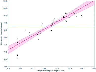 | ||
| Fig. 4 Impact of temperature on % conversion determined by 1H NMR spectroscopy in the Vapourtec flow process. | ||
In summary, through rapid sequential analysis of the key reaction parameters we determined the optimal working window for this flow reaction to be 120 °C, with an input rate of 0.3 mL min−1 using a 3.74 mol dm−3 (1![[thin space (1/6-em)]](https://www.rsc.org/images/entities/char_2009.gif) :
:![[thin space (1/6-em)]](https://www.rsc.org/images/entities/char_2009.gif) 2 g mL−1) sulfuric acid solution of the malic acid. This equated to a residence time of ∼3 min (ref. 50) equating to a throughput of 11.2 g h−1 in a conversion of ∼87% which upon quenching and isolation allows a 68% yield.
2 g mL−1) sulfuric acid solution of the malic acid. This equated to a residence time of ∼3 min (ref. 50) equating to a throughput of 11.2 g h−1 in a conversion of ∼87% which upon quenching and isolation allows a 68% yield.
Synthesis of methyl coumalate
Having established a working flow procedure to generate the coumalic acid intermediate we next considered the methylation step. Our approach was to first optimise the esterification step in isolation before attempting to telescope the whole sequence directly from malic acid. Furthermore, this interruption to the flow sequence, creating a two-stage process, allows for easy degassing of the first stage process prior to progression of the reactants. In addition, dilution of the crude sulfuric acid product (3.74 mol dm−3 – an exothermic process) with methanol greatly decreases the viscosity, making the solution much easier to pump through the second stage.To assess the impact of concentration three different solutions (1.99, 2.35, 2.89 mol dm−3) based upon the first stage dilution were prepared and passed through a short coil reactor (2.75 mL) housed in a Polar Bear Plus system maintained at 90 °C (Scheme 8). The outcomes were analysed by 1H NMR spectroscopy of the crude outputs, using the characteristic peaks HA and HB. This showed a viable working concentration of ∼2.35 mol dm−3.
Based upon these preliminary results an additional six experiments were performed centred on the 2.35 mol dm−3 concentration, varying residence time by altering the reactor coils and the flow rate (Table 2).
A working residence time of 8.25 min was sufficient to ensure quantitative conversion of the coumalic acid. Longer reactions, although displaying full conversion, also led to higher levels of product decomposition in line with the observation of Ashworth et al. in batch.16
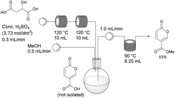
Having established the necessary individual processing requirements, the sequence was evaluated and tested as a telescoped flow synthesis (Scheme 9). A stock solution of malic acid (3.73 mol dm−3) was pumped using a Masterflex L/S peristaltic pump at 0.3 mL min−1 into two sequentially linked 10 mL PFA tubular reactors housed on the Vapourtec system heated at 120 °C (3 min residence time). The exiting product stream containing the crude coumalic acid was collected into a magnetically stirred and vented flask, to which methanol was constantly added via a second pump (channel 1 on the Vapourtec system) at 0.5 mL min−1. The methanol containing reaction mixture was pumped (channel 2 on the Vapourtec unit) at 1 mL min−1 into an 8.25 mL PFA coil reactor housed on a Polar Bear Plus reactor maintained at 90 °C (8.25 min residence time). The output stream containing methyl coumalate was collected as a batch and quenched with H2O resulting in the formation of a precipitate of the crude product which was isolated by filtration in 53% yield, generating a throughput of methyl coumalate of 1.65 g h−1.
This flow approach gives a modest improvement in the overall isolated yield compared to the equivalent one-pot batch sequence. The reaction times are very much shortened using an elevated temperature for each stage. In addition, by changing from batch to flow, the gas production and foaming encountered in the first step are no longer an issue. Additionally the viscosity of the sulfuric acid has been shown to be a major factor in the effective flow processing of the first step of the process, determining residence times and flow consistency. Indeed, the achievable pumping speed depends on the viscosity of the solutions which limits the speed material can be processed, therefore limiting the throughput of material.
Process intensification
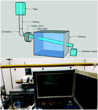
In our above investigations of coumalic acid formation it was shown that temperature was a critical reaction parameter and that liberation of the gaseous by-product (CO) also benefited the reaction. Furthermore, the high viscosity of the reaction mixture and issues encountered with reliable pumping of the viscous starting solution motivated us to consider a gravity fed system in a new design of reactor. Having considered the various options amenable to the process we elected to pursue a simple heated rotating tube design (Fig. 5).The rotating tube design selected was anticipated to furnish a thin film flow (promoting rapid thermal transfer and presenting a high surface area for release of the CO/H2O vapours) of the starting material which would traverse under gravity/centrifugal force along the work-tube heated in an oven to exit and be collected at the end of the reactor. Modification of the reaction temperature could be readily achieved through changes to the oven and residence times could be influenced by both rotation speed and potentially the angle/diameter of the tube's slope. In practice, the angle at which the work-tube was held was fixed in this prototype unit at 12° below horizontal, but would be expected to affect the fluidic flow and hence be a variable that would impact upon conversion.
To construct the prototype reactor, a laboratory glass drying oven was modified by drilling holes (diameter = 50.8 mm) through the left- and right-hand sides with a 12° decline (left → right). A glass work-tube (Smith Scientific R/38, outer diameter = 38.0 ± 0.8 mm, inner diameter = 36 mm) was inserted through the holes and one end connected to a rotary drive taken from a Büchi rotary evaporator (Rotavapor R-124). The opposing end of the glass tube was supported with a custom-made bench roller yoke to ensure smooth rotation. The drive motor enabled the glass tube to be spun at a controlled rotation speed. To dispense the reaction media various sizes of suspended dropping funnels could be connected via a short length of wide bore PTFE tubing (outer diameter = 8 mm, inner diameter = 5 mm) to run into the mouth of the work-tube. We nicknamed this reactor design the Heated Rotating flow reactor (abbreviated to the HeRo reactor, Fig. 5).
A systematic investigation was conducted into the relationships between various reaction parameters and the conversion/yield of the malic acid to coumalic acid process. To aid in optimisation a full experimental domain was interrogated through a central composite design (CCD). Components tested included the temperature, rotation and reactant addition speeds, as well as the concentration of the stock solution and the diameter of the rotating work-tube. From our previous experiments we knew this to be a complex reaction as during the course of the reaction, the viscosity of the reaction mixture decreases as the temperature of the solution increases. In addition, as the reaction progresses, gases (CO and water vapours) are produced which are now able to easily escape the thin film of the reacting mixture as it travels down the work-tube; this causes the mass of the solution to decrease (and change viscosity). The required residence time for the material processing depends on the interplay between all these factors but was typically found to fall in the range of 1–2 min. From the full principle component analysis several process-critical parameters emerged as dominating the conversion and isolated yield of the desired product. These were rotation speed, temperature, residence time and substrate addition rate.
Rotation speed
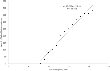
At certain temperatures and rotation speeds, the reaction mixture forms a helical fluidic path which can be controlled (Fig. 6). The tightness of this helix, its length and the number of turns depended on the speeds of rotation and substrate addition rate, and was due in part to the high viscosity of the solution. The entire process can be described as a rivulet wetting the surface of a rotating heated inclined cone. There are two phases (liquid and gaseous) and it can be further considered as an evaporation process due to the gas production. As indicated previously the current set-up is too complex to easily model, and the helical behaviour of the rivulet depends on too many variables. To highlight this behaviour, a stream of water or EtOAc did not form a similar rivulet flow, but instead wet the entire inner surface of the work-tube.The effects of the rotation speed on the characteristics of the helix were examined at an addition rate of 10.14 mL min−1 and a temperature of 110 °C. At rotation speeds below 7 rpm, no helix was observed. As the rotation speed increases, the length of the helix increases approximately linearly (Fig. 7). The maximum would be 600 mm, since this is the full length of the work-tube. As the rotation speed increases, the helix becomes ‘tighter’, and the rise of each helix in one revolution decreases.
A simple equation to describe the path length is as follows, where N = number of turns; H = rise of helix in one revolution (mm); r = radius (36 mm); Lh = length of helical behaviour (eqn (1)).
 | (1) |
A series of manipulated helices which exhibited full helical behaviour (Lh = 600 mm) were created by changing the rotation speed and addition rate, and are shown below (Table 3).
| Row | Number of turns, N | Rise of helix in one revolution, H/mm | Path length, D/mm | D/600 |
|---|---|---|---|---|
| 1 | 10 | 60 | 1170 | 1.95 |
| 2 | 13 | 46 | 1440 | 2.40 |
| 3 | 14 | 43 | 1530 | 2.55 |
| 4 | 60 | 10 | 6060 | 10.1 |
| 5 | 120 | 5 | 12![[thin space (1/6-em)]](https://www.rsc.org/images/entities/char_2009.gif) 100 100 |
20.1 |
For the most extreme example (row 5, Table 3), it was possible to increase the path length (relative to the linear straight traverse of the tube) by more than 20 times, so that the material will have travelled more than 12 metres as opposed to the direct flow path of 0.6 m experienced with no rotation. Even at low rotation speeds of 20 rpm, high conversions are possible if the temperature is sufficient. By examining a series at fixed temperature (for example, the blue data points in Fig. 8 at 70 °C), there is an approximately linear trend relating rotation speed and conversion.
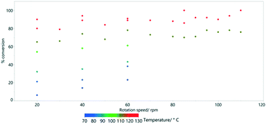 | ||
| Fig. 8 The effect of rotation speed on % conversion estimated by 1H NMR spectroscopy for the HeRo process. | ||
Reaction temperature is however much more important than the rotation speed in determining conversion (Fig. 9). This was previously shown as a key parameter in the simple Vapourtec assembled flow system described above (Fig. 4).
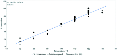 | ||
| Fig. 9 The linear relationship between temperature and % conversion estimated by 1H NMR spectroscopy. Line of best fit: y = −90.1 + 1.47x and R2 = 0.935. | ||
Other factors were also briefly investigated. The diameter of the work-tube would be expected to have an effect on conversion, as increasing the diameter should increase conversion by providing a longer residence time (through helical motion). The general phenomenon can be illustrated by looking at the comparable conversions of two tube diameters; 44 (51%) and 36 (23%) mm i.d., at a fixed temperature (110 °C) and rotation (14 rpm). The reduced radius of the 36 mm work-tube will shorten the path length by a factor of 2.75 compared to the 44 mm. In our HeRo system the tubing diameter used imposed operational restrictions on the rotation speed possible due to the higher loading placed on the rotary drive and increased vibrations resulting in instability at higher revolutions (44 mm i.d., maximum = 28 rpm). A more stable system was found using the 36 mm i.d. tubing which allowed rotation speeds of up to 120 rpm.
Test reactions were also performed with a higher concentration stock solution (7.46 mol dm−3), but these resulted in significantly lower conversions; 12% compared to 45% at 3.73 mol dm−3 (100 °C, 14 rpm). Note the discussion above on acid stoichiometry.
One of the benefits but also a limitation of this set-up is the use of a dropping funnel as the substrate dispensing tank. This does not give easily adjusted and quantitative control of the addition rate, however due to the viscosity and high density of the material the addition rate does not significantly vary with the volume/height of solution in the dropping funnel. Indeed, the steady-state behaviour persists for a large proportion of the dropping funnel's capacity. Interestingly there wasn't a meaningful correlation between conversion and addition rate in the range evaluated (1.25–3.00 mL min−1).
HeRo model
A simplified but representative model of the HeRo system was created, using temperature and rotation speed as the two key factors. The most important factor in determining conversion was temperature (Fig. 10 and 11).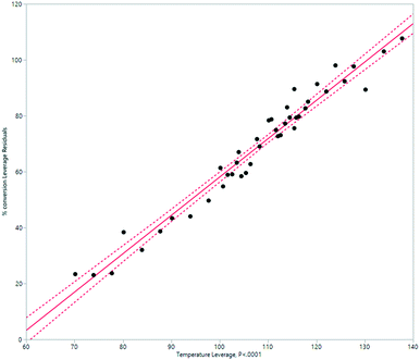 | ||
| Fig. 10 Modelling the HeRo process, plotting temperature against % conversion estimated by 1H NMR spectroscopy. | ||
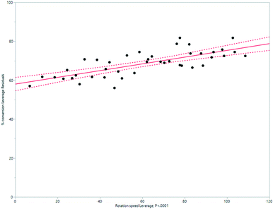 | ||
| Fig. 11 Modelling the HeRo process, demonstrating the relationship between rotation speed and % conversion estimated by 1H NMR spectroscopy. | ||
Using the model, a processing window was established equating to 3.73 mol dm−3 of malic acid in conc. sulfuric acid, at 120 °C, an addition rate of 3 mL min−1 and a reactor rotation speed of 60 rpm. The reactor was run for an initial period of 15 minutes to reach steady state and then the output collected for a further 8 hours of continuous operation. The mixture was divided, and half was quenched with ice water and allowed to precipitate enabling isolation of 143 g of high quality coumalic acid representing a 76% yield. The second portion of reaction mixture was diluted with methanol (3![[thin space (1/6-em)]](https://www.rsc.org/images/entities/char_2009.gif) :
:![[thin space (1/6-em)]](https://www.rsc.org/images/entities/char_2009.gif) 5) and progressed at 6.5 mL min−1 through a 52 mL flow coil reactor maintained at 90 °C. This gave a complete conversion to the corresponding methyl coumalate which was isolated in 58% overall yield for the two-step process.
5) and progressed at 6.5 mL min−1 through a 52 mL flow coil reactor maintained at 90 °C. This gave a complete conversion to the corresponding methyl coumalate which was isolated in 58% overall yield for the two-step process.
Comparing the syntheses of coumalic acid
Two measures of efficiency and productivity were used to compare the processes (Table 4).| Process | Throughput/g h−1 | Space–time yield/kg m−3 h−1 |
|---|---|---|
| Wiley 1963 (ref. 15) | 17.6 (100 g) | 55.1 |
| Batch | 8.5 (200 g) | 8.5 |
| Small-scale flow | 11.2 | 560 |
| HeRo flow reactor | 35.8 | 184.1 |
The throughput and space–time yield (STY) for the batch process are both low. This is due to the longer reaction time (6–8 h) and the use of a large vessel necessary to accommodate the reaction foaming (release of CO). Moving to the small-scale Vapourtec flow process (Masterflex L/S peristaltic pumps), the throughput and STY increased, but were still limited by the achievable pumping speed. Finally, the HeRo reactor yields a much higher throughput, and a STY increase of between 3.3 and 21.7 times the batch process. The pumping speed limitation has also been removed, and the residence time is similar to that of the Vapourtec process.
Inverse electron demand Diels–Alder reactions with methyl coumalate
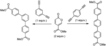
The original stimulus to develop a scalable route to methyl coumalate was as a sustainable starting material for a proposed inverse electron demand Diels–Alder/retro-Diels–Alder sequence with electron-rich alkynes to provide metal-free syntheses of terphenyls for use in OLED applications (Scheme 10).As a starting point it had previously been reported that amino functionalised pyranones underwent reaction with activated alkene acceptors (maleic anhydride and N-substituted maleimides) either thermally in tetralin (207 °C) or in the presence of tert-butanol under microwave irradiation to generate fused biaryl aniline derivatives.51–53 Also of interest was that simple mono substituted acetylenes (R = CO2Me, Ph) could be utilised in similar cycloaddition–reversion sequences generating aromatic rings.54
Based upon these results we heated a 1![[thin space (1/6-em)]](https://www.rsc.org/images/entities/char_2009.gif) :
:![[thin space (1/6-em)]](https://www.rsc.org/images/entities/char_2009.gif) 1 ratio of the coumalic methyl ester with phenylacetylene (10 mmol) in tert-butanol under microwave irradiation for 2, 4 and 6 h at 170 °C. Analysis of the crude reactions by 1H-NMR indicated 48, 67 and 74% conversion respectively. However, after each reaction, the pressure in the microwave vial had increased significantly (8–12 bar residual pressure) due to the production of carbon dioxide in the final decarboxylation step as well as potential decomposition of the solvent. Furthermore, higher reaction temperatures could not be achieved without exceeding pressure safety limits. Consequently, based upon its microwave heating efficiency, high solvating ability and lower vapour pressure we changed to 1,4-dioxane as the reaction solvent.55–58 This allowed us to achieve a controlled reaction temperature of 200 °C (8–10 bar working pressure) and also gave a lower final post-reaction pressure of >0.5 bar. Conducting the repeat reactions at this elevated temperature gave increased 1H-NMR conversions of 83, 88 and 91% respectively. In an attempt to push the reaction to completion we next employed a slight excess of the coumalic ester (1.2 equiv.) which led to quantitative conversion after 4 h and an isolated yield of 93% following chromatographic separation. As a further validation we applied the same reaction conditions to the transformation of the less activated 1-phenyl-3-butyne which satisfyingly also reacted to yield 91% of the expected aryl derivative after purification.
1 ratio of the coumalic methyl ester with phenylacetylene (10 mmol) in tert-butanol under microwave irradiation for 2, 4 and 6 h at 170 °C. Analysis of the crude reactions by 1H-NMR indicated 48, 67 and 74% conversion respectively. However, after each reaction, the pressure in the microwave vial had increased significantly (8–12 bar residual pressure) due to the production of carbon dioxide in the final decarboxylation step as well as potential decomposition of the solvent. Furthermore, higher reaction temperatures could not be achieved without exceeding pressure safety limits. Consequently, based upon its microwave heating efficiency, high solvating ability and lower vapour pressure we changed to 1,4-dioxane as the reaction solvent.55–58 This allowed us to achieve a controlled reaction temperature of 200 °C (8–10 bar working pressure) and also gave a lower final post-reaction pressure of >0.5 bar. Conducting the repeat reactions at this elevated temperature gave increased 1H-NMR conversions of 83, 88 and 91% respectively. In an attempt to push the reaction to completion we next employed a slight excess of the coumalic ester (1.2 equiv.) which led to quantitative conversion after 4 h and an isolated yield of 93% following chromatographic separation. As a further validation we applied the same reaction conditions to the transformation of the less activated 1-phenyl-3-butyne which satisfyingly also reacted to yield 91% of the expected aryl derivative after purification.
With a set of working conditions, we turned our attention to the processing of the target bis-acetylenes. Commencing our evaluation, we started with a reaction stoichiometry of 2![[thin space (1/6-em)]](https://www.rsc.org/images/entities/char_2009.gif) :
:![[thin space (1/6-em)]](https://www.rsc.org/images/entities/char_2009.gif) 1 in respect to the pyranone to the corresponding 1,3- or 1,4-diethynylbenzene, applying a heating sequence of 200 °C in 1,4-dioxane for 4 h. These acetylenes proved to be less reactive, furnishing mixtures of the mono- and di-functionalised products as well as indicating unreacted starting materials (8–12%; Table 5). Extending the heating period to 8 h gave better results but still resulted in incomplete conversion. Finally, by utilizing an excess of the pyranone (2.4
1 in respect to the pyranone to the corresponding 1,3- or 1,4-diethynylbenzene, applying a heating sequence of 200 °C in 1,4-dioxane for 4 h. These acetylenes proved to be less reactive, furnishing mixtures of the mono- and di-functionalised products as well as indicating unreacted starting materials (8–12%; Table 5). Extending the heating period to 8 h gave better results but still resulted in incomplete conversion. Finally, by utilizing an excess of the pyranone (2.4![[thin space (1/6-em)]](https://www.rsc.org/images/entities/char_2009.gif) :
:![[thin space (1/6-em)]](https://www.rsc.org/images/entities/char_2009.gif) 1 ratio) with an 8 h reaction time, high conversion to the desired products could be achieved.
1 ratio) with an 8 h reaction time, high conversion to the desired products could be achieved.
| Acetylene | Time, ratio (Py![[thin space (1/6-em)]](https://www.rsc.org/images/entities/char_2009.gif) : :![[thin space (1/6-em)]](https://www.rsc.org/images/entities/char_2009.gif) Acet) Acet) |
Ratio (SM![[thin space (1/6-em)]](https://www.rsc.org/images/entities/char_2009.gif) : :![[thin space (1/6-em)]](https://www.rsc.org/images/entities/char_2009.gif) mono mono![[thin space (1/6-em)]](https://www.rsc.org/images/entities/char_2009.gif) : :![[thin space (1/6-em)]](https://www.rsc.org/images/entities/char_2009.gif) bis) bis) |
|---|---|---|
| All reactions were conducted on 10 mmol acetylene scale, 200 °C under microwave irradiation. 1H-NMR calibration of starting acetylene and intermediate non-substituted acetylene against 1,3-dimethoxybenzene as an internal standard. | ||
| 1,3- | 4 h, (2![[thin space (1/6-em)]](https://www.rsc.org/images/entities/char_2009.gif) : :![[thin space (1/6-em)]](https://www.rsc.org/images/entities/char_2009.gif) 1) 1) |
12![[thin space (1/6-em)]](https://www.rsc.org/images/entities/char_2009.gif) : :![[thin space (1/6-em)]](https://www.rsc.org/images/entities/char_2009.gif) 38 38![[thin space (1/6-em)]](https://www.rsc.org/images/entities/char_2009.gif) : :![[thin space (1/6-em)]](https://www.rsc.org/images/entities/char_2009.gif) 50 50 |
| 1,4- | 4 h, (2![[thin space (1/6-em)]](https://www.rsc.org/images/entities/char_2009.gif) : :![[thin space (1/6-em)]](https://www.rsc.org/images/entities/char_2009.gif) 1) 1) |
8![[thin space (1/6-em)]](https://www.rsc.org/images/entities/char_2009.gif) : :![[thin space (1/6-em)]](https://www.rsc.org/images/entities/char_2009.gif) 47 47![[thin space (1/6-em)]](https://www.rsc.org/images/entities/char_2009.gif) : :![[thin space (1/6-em)]](https://www.rsc.org/images/entities/char_2009.gif) 43 43 |
| 1,3- | 8 h, (2![[thin space (1/6-em)]](https://www.rsc.org/images/entities/char_2009.gif) : :![[thin space (1/6-em)]](https://www.rsc.org/images/entities/char_2009.gif) 1) 1) |
1![[thin space (1/6-em)]](https://www.rsc.org/images/entities/char_2009.gif) : :![[thin space (1/6-em)]](https://www.rsc.org/images/entities/char_2009.gif) 19 19![[thin space (1/6-em)]](https://www.rsc.org/images/entities/char_2009.gif) : :![[thin space (1/6-em)]](https://www.rsc.org/images/entities/char_2009.gif) 80 80 |
| 1,4- | 8 h, (2![[thin space (1/6-em)]](https://www.rsc.org/images/entities/char_2009.gif) : :![[thin space (1/6-em)]](https://www.rsc.org/images/entities/char_2009.gif) 1) 1) |
2![[thin space (1/6-em)]](https://www.rsc.org/images/entities/char_2009.gif) : :![[thin space (1/6-em)]](https://www.rsc.org/images/entities/char_2009.gif) 23 23![[thin space (1/6-em)]](https://www.rsc.org/images/entities/char_2009.gif) : :![[thin space (1/6-em)]](https://www.rsc.org/images/entities/char_2009.gif) 75 75 |
| 1,3- | 8 h, (2.4![[thin space (1/6-em)]](https://www.rsc.org/images/entities/char_2009.gif) : :![[thin space (1/6-em)]](https://www.rsc.org/images/entities/char_2009.gif) 1) 1) |
0![[thin space (1/6-em)]](https://www.rsc.org/images/entities/char_2009.gif) : :![[thin space (1/6-em)]](https://www.rsc.org/images/entities/char_2009.gif) 3 3![[thin space (1/6-em)]](https://www.rsc.org/images/entities/char_2009.gif) : :![[thin space (1/6-em)]](https://www.rsc.org/images/entities/char_2009.gif) 97 97 |
| 1,4- | 8 h, (2.4![[thin space (1/6-em)]](https://www.rsc.org/images/entities/char_2009.gif) : :![[thin space (1/6-em)]](https://www.rsc.org/images/entities/char_2009.gif) 1) 1) |
0![[thin space (1/6-em)]](https://www.rsc.org/images/entities/char_2009.gif) : :![[thin space (1/6-em)]](https://www.rsc.org/images/entities/char_2009.gif) 2 2![[thin space (1/6-em)]](https://www.rsc.org/images/entities/char_2009.gif) : :![[thin space (1/6-em)]](https://www.rsc.org/images/entities/char_2009.gif) 98 98 |
As a simple proof of concept for the direct flow scale-up of the reaction we took a stock solution (0.35 M) of the 1,3-diethynylbenzene and pyranone (1![[thin space (1/6-em)]](https://www.rsc.org/images/entities/char_2009.gif) :
:![[thin space (1/6-em)]](https://www.rsc.org/images/entities/char_2009.gif) 2.4 ratio) and passed this mixture through a heated 40 mL stainless steel coil operated with a 250 psi in-line back pressure regulator placed at the exit. Using a flow rate of 150 μL min−1 (residence time of 4.4 h) and a reactor temperature of 220 °C we achieved a steady state conversion of 89% and a productivity of 850 mg h−1 based upon a 78% isolated yield. This flow set-up was successfully run uninterrupted for 33 h before being stopped, enabling over 28 g of the product to be isolated.
2.4 ratio) and passed this mixture through a heated 40 mL stainless steel coil operated with a 250 psi in-line back pressure regulator placed at the exit. Using a flow rate of 150 μL min−1 (residence time of 4.4 h) and a reactor temperature of 220 °C we achieved a steady state conversion of 89% and a productivity of 850 mg h−1 based upon a 78% isolated yield. This flow set-up was successfully run uninterrupted for 33 h before being stopped, enabling over 28 g of the product to be isolated.
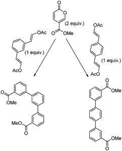
Encouraged by the success of these approaches, we ventured to expand the substrate scope and attempted to access the corresponding regioisomeric products by reacting methyl coumalate with the readily prepared enol acetate partners (Scheme 11). These substrates, based upon the reactivity of the equivalent vinyl ethers, would be expected to deliver the alternative meta derivatives.13 Unfortunately, it was shown that these species were almost entirely unreactive allowing mainly starting material to be recovered after 16 h of heating at 200 °C. Although disappointing, this aptly demonstrates the sensitive electronics of this transformation. Indeed, the equivalent reaction with 1-methoxy-2-phenylethylene when trialled progressed to 38% in our hands (16 h of heating at 200 °C; note 51% reported in the literature13), whereas the equivalent vinyl acetate substrate was again essentially inactive (<6% after 16 h). We are currently undertaking computational calculations to determine the feasible partners for this transformation which we hope to be able to report in the near future.
Conclusions
We have demonstrated a new, intensified continuous flow process for the synthesis of coumalic acid from malic acid, a biorenewable feedstock platform compound. As part of this work, we have built a new type of flow reactor, with a heated rotating work-tube, which we anticipate being useful in a diverse range of chemical reactions. In addition, we have shown that methyl coumalate could be used in several inverse electron demand Diels–Alder reactions to generate terphenyls with value in the areas of OLEDs and molecular electronics.Conflicts of interest
There are no conflicts to declare.Acknowledgements
The authors would like to gratefully acknowledge financial support from the Royal Society (IRB and LKS).References
- J. M. Tour, Acc. Chem. Res., 2000, 33, 791–804 CrossRef PubMed.
- D. Astruc, E. Boisselier and C. Ornelas, Chem. Rev., 2010, 110, 1857–1959 CrossRef PubMed.
- P. M. Delaney, J. E. Moore and J. P. A. Harrity, Chem. Commun., 2006, 3323–3325 RSC.
- P. M. Delaney, D. L. Browne, H. Adams, A. Plant and J. P. A. Harrity, Tetrahedron, 2008, 64, 866–873 CrossRef.
- J. D. Kirkham, P. M. Delaney, G. J. Ellames, E. C. Row and J. P. A. Harrity, Chem. Commun., 2010, 46, 5154–5156 RSC.
- J. J. Lee and G. A. Kraus, Green Chem., 2014, 16, 2111–2116 RSC.
- G. A. Kraus, G. R. Pollock III, C. L. Beck, K. Palmer and A. H. Winter, RSC Adv., 2013, 3, 12721–12725 RSC.
- J. J. Lee and G. A. Kraus, Tetrahedron Lett., 2013, 54, 2366–2368 CrossRef.
- M. W. Smith and S. A. Snyder, J. Am. Chem. Soc., 2013, 135, 12964–12967 CrossRef PubMed.
- M. Feng and X. Jiang, Chem. Commun., 2014, 50, 9690–9692 RSC.
- W. R. Gutekunst and P. S. Baran, J. Am. Chem. Soc., 2011, 133, 19076–19079 CrossRef PubMed.
- W. R. Gutekunst, R. Gianatassio and P. S. Baran, Angew. Chem., Int. Ed., 2012, 51, 7507–7510 CrossRef PubMed.
- J. J. Lee, G. R. Pollock III, D. Mitchell, L. Kasuga and G. A. Kraus, RSC Adv., 2014, 4, 45657–45664 RSC , see also Patent WO2014/189926A1.
- H. von Pechmann, Justus Liebigs Ann. Chem., 1891, 264, 261–309 CrossRef.
- R. H. Wiley and N. R. Smith, Org. Synth., 1963, 4, 201–202 Search PubMed.
- I. W. Ashworth, M. C. Bowden, B. Dembofsky, D. Levin, W. Moss, E. Robinson, N. Szczur and J. Virica, Org. Process Res. Dev., 2003, 7, 74–81 CrossRef.
- T. Kaminski and G. Kirsch, J. Heterocycl. Chem., 2008, 45, 229–234 CrossRef.
- S. Maeda, Y. Obora and Y. Ishii, Eur. J. Org. Chem., 2009, 4067–4072 CrossRef.
- P. Rosenmund, M. Casutt and M. Wittich, Liebigs Ann. Chem., 1990, 233–238 CrossRef.
- W. T. Caldwell, F. T. Tyson and L. Lauer, J. Am. Chem. Soc., 1944, 66, 1479–1484 CrossRef.
- C. R. Engel, A. F. de Krassny, A. Bélanger and G. Dionne, Can. J. Chem., 1973, 51, 3263–3271 CrossRef.
- T. Werpy and G. Petersen, Top Value Added Chemicals from Biomass, vol. I, 2004 Search PubMed.
- W. L. Luyben, Ind. Eng. Chem. Res., 2011, 50, 1231–1246 CrossRef.
- J. M. Mavity, E. E. Zetterholm and G. L. Hervert, Ind. Eng. Chem., 1946, 38(8), 829–832 CrossRef.
- E. Karakhanov, A. Maximov, Y. Kardasheva, V. Semernina, A. Zolotukhina, A. Ivanov, G. Abbott, E. Rosenberg and V. Vinokurov, ACS Appl. Mater. Interfaces, 2014, 6(11), 8807–8816 CrossRef PubMed.
- J.-C. Wu, D.-S. Liu and A.-N. Ko, Catal. Lett., 1993, 20, 191 CrossRef.
- W. Oganowski, J. Hanuza, H. Drulis, W. Mista and L. Macalik, Appl. Catal., 1996, 136, 143 CrossRef.
- J. N. Michaels and C. G. Vayenas, J. Electrochem. Soc., 1984, 131(11), 2544–2550 CrossRef.
- H. M. Relles, Conversion of vinylbenzenes to ethynylbenzenes, US3594423A, 1971.
- X. A. Garcia, Erdoel Kohle, Erdgas, Petrochem., 1990, 43(3), 113–114 Search PubMed.
- J. Lian, R. McKenna, M. R. Rover, D. R. Nielsen, Z. Wen and L. R. Jarboe, J. Ind. Microbiol. Biotechnol., 2016, 43(5), 595–604 CrossRef PubMed.
- C. Liu, X. Men, H. Chen, M. Li, Z. Ding, G. Chen, F. Wang, H. Liu, Q. Wang, Y. O. Zhu, H. Zhang and M. Xian, Biotechnol. Biofuels, 2018, 11(14), 1–11 Search PubMed.
- Green Biorenewable Biocomposites: From Knowledge to Industrial Applications, ed. V. K. Thakur and M. R. Kessler, CRC Press, Taylor Francis Group, 2015, ISBN 978-1-4822-5267-5 Search PubMed.
- J. H. Boyer and W. Schoen, Org. Synth., 1956, 36, 44 CrossRef.
- H. F. Jiang, Y. X. Shen and Z. Y. Wang, Tetrahedron, 2008, 64, 508–514 CrossRef.
- A. Kishi, S. Sakaguchi and Y. Ishii, Org. Lett., 2000, 2, 523–525 CrossRef PubMed.
- C. A. Shukla and A. A. Kulkarni, Beilstein J. Org. Chem., 2017, 13, 960–987 CrossRef PubMed.
- M. Movsisyan, E. I. P. Delbeke, J. K. E. T. Berton, C. Battilocchio, S. V. Ley and C. V. Stevens, Chem. Soc. Rev., 2016, 45, 4892–4928 RSC.
- H. Kim, K.-I. Min, K. Inoue, D. J. Im, D.-P. Kim and J. Yoshida, Science, 2016, 352, 691–694 CrossRef PubMed.
- A. Adamo, R. L. Beingessner, M. Behnam, J. Chen, T. F. Jamison, K. F. Jensen, J.-C. M. Monbaliu, A. S. Myerson, E. M. Revalor, D. R. Snead, T. Stelzer, N. Weeranoppanant, S. Y. Wong and P. Zhang, Science, 2016, 352, 61–67 CrossRef PubMed.
- T. Tsubogo, H. Oyamada and S. Kobayashi, Nature, 2015, 520, 329–332 CrossRef PubMed.
- M. Baumann and I. R. Baxendale, Beilstein J. Org. Chem., 2015, 11, 1194–1219 CrossRef PubMed.
- J. Britton and C. L. Raston, Chem. Soc. Rev., 2017, 46, 1250–1271 RSC.
- N. Vasudevan, M. K. Sharma, D. S. Reddy and A. A. Kulkarni, React. Chem. Eng., 2018 10.1039/C8RE00025E.
- K. P. Cole, J. McClary Groh, M. D. Johnson, C. L. Burcham, B. M. Campbell, W. D. Diseroad, M. R. Heller, J. R. Howell, N. J. Kallman, T. M. Koenig, S. A. May, R. D. Miller, D. Mitchell, D. P. Myers, S. S. Myers, J. L. Phillips, C. S. Polster, T. D. White, J. Cashman, D. Hurley, R. Moylan, P. Sheehan, R. D. Spencer, K. Desmond, P. Desmond and O. Gowran, Science, 2017, 356, 1144–1150 CrossRef PubMed.
- A. Polyzos, M. O'Brien, T. P. Petersen, I. R. Baxendale and S. V. Ley, Angew. Chem., Int. Ed., 2011, 50(5), 1190–1193 CrossRef PubMed.
- M. O'Brien, N. Taylor, A. Polyzos, I. R. Baxendale and S. V. Ley, Chem. Sci., 2011, 2, 1250–1257 RSC.
- L. Yang and K. F. Jensen, Org. Process Res. Dev., 2013, 17(6), 927–933 CrossRef.
- K. Skowerski, S. J. Czarnocki and P. Knapkiewicz, ChemSusChem, 2014, 7(2), 536–542 CrossRef PubMed.
- R. E. Martin, F. Morawitz, C. Kuratli, A. M. Alker and A. I. Alanine, Eur. J. Org. Chem., 2012, 47–52 CrossRef.
- K. Kranjc and M. Kočevar, New J. Chem., 2005, 29, 1027–1034 RSC.
- K. Kranjc and M. Kocevar, Collect. Czech. Chem. Commun., 2006, 71, 667–678 CrossRef.
- K. Kranjc, B. Štefane, S. Polanc and M. Kočevar, J. Org. Chem., 2004, 69, 3190–3193 CrossRef PubMed.
- F. Effenberger and T. Ziegler, Chem. Ber., 1987, 120, 1339–1346 CrossRef.
- A. de la Hoz, Á. L. Díaz-Ortiz and A. Moreno, Chem. Soc. Rev., 2005, 34, 164–178 RSC.
- P. Linström, J. Tierney, B. Wathey and J. Westman, Tetrahedron, 2001, 57, 9225–9283 CrossRef.
- I. R. Baxendale, J. J. Hayward and S. V. Ley, Comb. Chem. High Throughput Screening, 2007, 10, 802–836 CrossRef PubMed.
- P. M. Gillespie, IChemE SYMPOSIUM SERIES, 2004, vol. 150, pp. 1–11 Search PubMed.
Footnote |
| † Electronic supplementary information (ESI) available: Synthetic and experimental details; analytical methods and spectra; videos of processes. See DOI: 10.1039/c8re00116b |
| This journal is © The Royal Society of Chemistry 2018 |


