Thermoformed fluoropolymer tubing for in-line mixing†
Received
21st June 2018
, Accepted 18th July 2018
First published on 18th July 2018
Abstract
We present a thermoforming method to make in-line micromixer in commercial fluoropolymer tubing. The technique is low-cost and easy to implement in the laboratory. Tested by dye tracing experiments, the tubular micromixers with surface screw patterns demonstrate excellent performance as characterized by the Villermaux–Dushman reaction and computational fluid dynamics (CFD) simulations. Results show that the formed static mixer performs better than coiled and straight tubes for the low Reynolds number (Re < 100) regime encountered in many laboratory flow chemistry experiments. The observations correlate well with residence time distribution (RTD) experiments revealing reduced dispersion. The improved performance of the screw-tube mixers is attributed to the forced rotating flow around the central axis. The new static mixer structures are employed in the synthesis of gold nanoparticles with high yield and narrower size distribution particles compared to results with coiled tubes.
Introduction
Fluoropolymer tubes are widely used for carrying out chemical reactions owing to their good chemical inertness to acids, bases, and most solvents.1,2 However, for the low Reynolds numbers encountered in typical laboratory flow chemistry experiments, reagent mixing in straight tubes is limited by molecular diffusion and the reaction mixture is subject to dispersion.3,4 In larger tubes, static mixers create cross-streamwise mixing, but they are difficult to obtain at reasonable cost in mm dimensions and in fluoropolymers. Coiled tubing is an often used method to enhance mixing in reaction systems built with fluoropolymer tubes.5,6 However, the intensity of the Dean vortices that create the mixing is strongly dependent on high flow rates of fluid, which can be problematic for flow chemistry studies with expensive reagents and slow kinetics.
Mixing challenges have driven two decades of research in enhancing mixing and reducing dispersion in microfluidic systems.7–9 Injecting an immiscible fluid into process fluid to create a segmented flow has been an effective strategy to reduce dispersion,10,11 but it requires the subsequent removal of the injected dispersant. Stroock et al.12 showed that an alternating herringbone pattern created imprinted on the bottom of a channel in polydimethylsiloxane (PDMS) could be an effective means of creating cross-streamwise mixing. Building upon this approach, we thought to create patterns on the inside of fluoropolymer tubes to act as built-in static micromixers. For that purpose, we developed a thermoforming method to turn commercial PFA (perfluoroalkoxy alkanes), FEP (fluorinated ethylene propylene) and Tefzel® (ETFE, ethylene tetrafluoroethylene) tubes into patterned tubular micromixers.
In the following sections, we describe the fabrication process and characterize the performance of the resulting “screw-tube micromixer” through dye visualization, the Villermaux–Dushman reaction, residence time distribution (RTD) measurements, and gold nanoparticles synthesis. Computational fluid dynamics (CFD) simulation provides further insight into the mixing enhancement mechanism of the screw-tube mixer.
Fluoropolymer in-line mixer fabrication
Fig. 1(a) shows the thermoforming fabrication procedure for a fluoropolymer micromixer. The first step was to machine two metal molds with engraved patterns (screw pitch = 1 mm, minor diameter = 1.4 mm, and major diameter = 2.2 mm) to generate the screw mixing structures. Then, a fluoropolymer tube (1.6 mm outer diameter, Idex Health & Science, USA) was sandwiched between the molds and tightened by bolts around the edges. The molds with the tube were subsequently placed in an oven under heat treatment at a constant temperature (defined below) for 1 h. The patterned fluoropolymer tube was released after cooling to room temperature. We tested this method with 3 commonly used fluoropolymer materials in flow chemistry studies PFA, FEP and Tefzel® (ETFE). The PFA tubes, with 3 different inner diameters (ID) of 0.5, 0.75, and 1.0 mm and the same outer dimeter (OD) of 1.6 mm, were fabricated using the mode with the same engraved structure, and screw patterns in the interior surface were successfully thermoformed, as shown in Fig. 1(b). The lower and upper bounds of the diameters (D1 and D2) according to the patterned screw structures were measured from the microscope pictures and summarized in Table 1. For FEP and ETFE, we only tested the tubes with 0.75 mm ID and 1.6 mm OD, as shown in Fig. 1(c), which had the same inner structures as the 0.75 mm ID PFA micromixer. Besides the screw mixing patterns, other mixing structures were fabricated by the thermoforming method, including a slant-grooved tunnel12 and a split-recombined tunnel,13 as shown in Fig. 1(c). Length details of the patterns to obtain these structures are given in Fig. S1 of the ESI.†
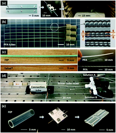 |
| | Fig. 1 Fabrication and application of the fluoropolymer mixers. (a) Fabrication procedure for the micromixers. Aluminum molds are first machined with screw patterns, and the structural details are shown in Fig. S1(a) of the ESI.† Then two assembled molds squeezing a 1.6 mm OD fluoropolymer tube are placed in an oven to implement heat treatment. (b) Fabricated PFA screw-tube micromixers. Those tubes are able to be connected to commercial PEEK (polyetheretherketone) fittings. They are also cut open and captured in a microscope to reveal the inner structures. (c) FEP and Tefzel® (ETFE) micromixers and other types of micromixers from the thermoforming method. This method works well in fabrication of FEP and ETFE with different colors and degrees of transparency. Fabrication of complicated patterns, including slant-grooved tunnel12 and split-recombined tunnel13 was also achieved. More details of the size parameters of the molds for the slant-grooved tunnel and the split-recombined tunnel are shown in Fig. S1(b) of the ESI.† (d) Application of the screw-tube micromixer. The mixer can be used following a commercial T-connector to implement reagents mixing in a flow chemistry platform. This mixing platform was used in the following Villermaux–Dushman reaction experiments and the gold nanoparticle preparation experiments. (e) Fabrication of a Y shape connector from a 6.4 mm FEP tube with the thermoforming method. The mode structure is shown in Fig. S1(c) of the ESI.† | |
Table 1 Inner screw structures of the micromixers
| Original tube IDs (mm) |
D
1 for the inner screw (mm) |
D
2 for the inner screw (mm) |
| 1.0 |
0.69 |
0.98 |
| 0.75 |
0.53 |
0.74 |
| 0.5 |
0.41 |
0.49 |
The heat treatment temperatures of PFA (T = 260 °C) and FEP (200 °C) were determined based on their melting points (Table S1 of the ESI†), while that of ETFE was optimized by experiments. The portions of the fluoropolymer tubes outside the molds were marginally influenced by the thermoforming process, so that commercial fittings (Idex Health & Science, USA) were able to allow easy assembly of the micromixer in the flow chemistry platform shown in Fig. 1(d). In addition, the color and degree of transparency of the fluoropolymer tubes were unaffected by the thermoforming process, which made it possible to visualize the flow in the mixer with dye tracing experiments, as described in the following section. The length of all mixers was 72 mm in this study due to the size of the oven. However, if heating rods and temperature controllers were added into the metal molds (Fig. S2†), the thermoforming process could be carried out without an oven, opening the opportunity for extending the mixing length by repeatedly squeezing and thermoforming procedures.
Fluoropolymer tubing connectors could also be fabricated using this method with the support of metal pillars inside the fluoropolymer tubes, as shown in Fig. 1(e). In this case, a 6.4 mm OD FEP tube with 0.5 mm thick wall (McMaster, USA) was squeezed with the molds in Fig. S1(c).† In order to seal the contact regions of the connector, the heat treatment temperature (T = 240 °C) was set close to the melting point of the material, and therefore the pillars inserted were very important for supporting the connecting holes. After the metal molds cooled down to room temperature, the pillars were removed revealing the thermoformed connector. This connector was employed in the dye tracing experiment to show the color of the fluids prior to mixing. For more details of the fabrication of the connector and the micromixers, please refer to the ESI.†
Mixing characterization
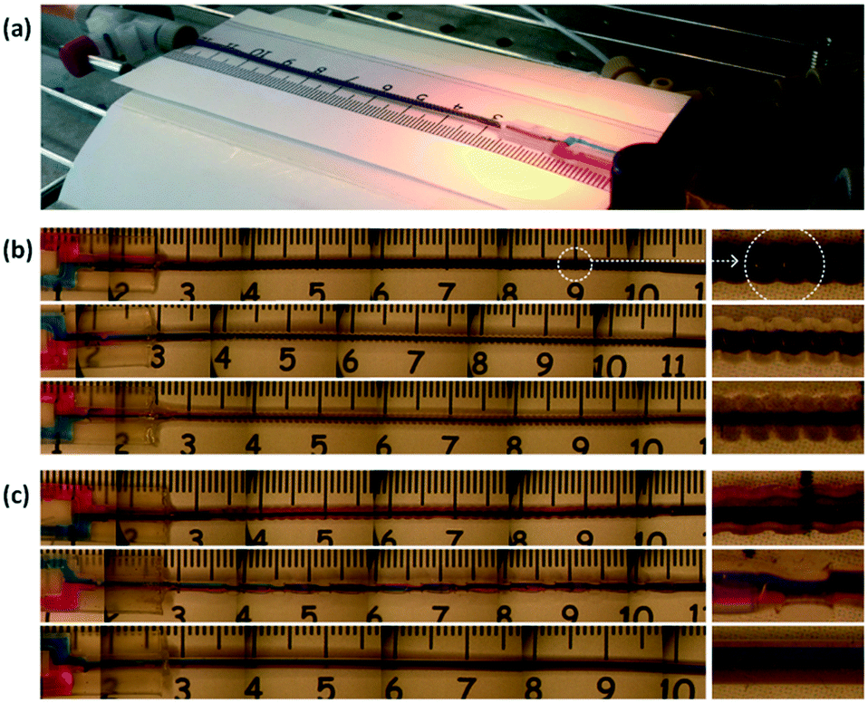
In order to demonstrate fluid mixing in the micromixers, dye-tracing experiments were carried out in the first place with blue (0.062 wt% Erioglaucine from Sigma-Aldrich) and red (0.10 wt% Rhodamine B from Sigma-Aldrich) aqueous solutions as shown in Fig. 2(a). The first examined was the screw-tube micromixers. The colored fluids were introduced into the mixer through the thermoformed connector in Fig. 1(e). Flow rates were controlled by syringe pumps (PHD Ultra 2000, Harvard Apparatus) and mixing was visualized by a stereoscopic microscope (Leica) and recorded by a digital camera (Nikon). Limited by the microscope's field of view, images were jointed with the help of a ruler to show the whole mixer (Fig. 2b). As injecting the two solutions with identical flow rates, the blended liquid quickly turned into purple after eluting only 1–2 cm of the mixer. These quick color changes were observed at total flow rates (Qblue + Qred) from 0.3 to 6 mL min−1. Enlarged pictures on the right side of Fig. 2(b) show the uniformity of the purple color along the tube. Supplementary pictures for the experiments with non-identical flow rates are exhibited by Fig. S3 in the ESI.† Fast mixing was also observed with flow rate ratios (Qblue/Qred) of 2.0 and 5.0. In comparison, Fig. 2(c) indicates the mixing in the home-made slant-grooved tunnel, split-recombined tunnel, and a straight tube, respectively. According to the pictures, mixing is not finished in either the 72 mm long slant-grooved tunnel or the split-recombined tunnel. It is very likely because the mixing structures obtained from our present thermoforming procedures are not as precise as the ones made by etching or planography, which has better structural control during fabrication.14,15 In addition, the straight tube experiment confirms that mixing in it is mainly dependent on molecular diffusion between the colored layers shown in Fig. 2(c). Supplementary videos are attached in the ESI† to visualize the typical dye tracing experiments.
 |
| | Fig. 2 Joined images from the dye tracing experiments. (a) The experimental platform. (b) The screw-tube micromixers. From top to bottom: original tube ID = 1.0 mm, Qblue = Qred = 1.0 mL min−1; original tube ID = 0.75 mm, Qblue = Qred = 1.0 mL min−1; original tube ID = 0.5 mm, Qblue = Qred = 0.5 mL min−1. (c) Other mixers and a straight tube. From top to bottom: slant-grooved tunnel, original tube ID = 1.0 mm, Qblue = Qred = 1.0 mL min−1; split-recombined tunnel, original tube ID = 0.75 mm, Qblue = Qred = 1.0 mL min−1; straight tube: tube ID = 0.75 mm, Qblue = Qred = 1.0 mL min−1. Details of the patterns on the molds are provided in Fig. S1 of the ESI.† | |
To further understand the mixing mechanism, we conducted CFD simulations with COMSOL Multiphysics 5.3a of the 3D internal flow patterns and species concentration profiles in the screw-tube micromixer. Since the Reynolds number (Re) was <150 in all experiments examined, laminar flow models with stationary solvers were employed to solve the continuity equation, the Naiver–Stokes (NS) equation and the diffusion–convection equation in eqn. S1 to S3.† Due to the repetitive structure of the screw tube mixer, we first simulated a 10 mm long domain rather than the full length of 72 mm to understand the influence of geometry on mixing. 7 million tetrahedron gird cells with 0.0415 mm maximum mesh length were used in the calculation, which cost about 3 h time in a ThinkPad P50 Workstation with Intel Core i7-6820HQ CPU @ 2.70 GHz. The effect of numerical diffusion on the calculation results could be neglected based on a mesh independent study (details provided in the ESI†). In Fig. 3(a), the arrows (adjusted by the according velocity magnitude) show that the screw leads to a rotating flow field along the axial direction. Fig. 3(b) reveals the curved streamlines in the micromixer and the velocity magnitude distributions in different axial cross-sections, exhibiting a rotating flow path. Additionally, Fig. 3(c) shows the dye concentration profiles, which further confirm that the working mechanism of the screw-tube mixer is to force fluid to rotate along the axis of the mixer (for more details of the simulation settings, please refer to the ESI†).
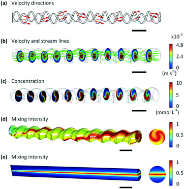 |
| | Fig. 3 CFD simulations for the 3D fluid flow and concentration profiles in a 10 mm long screw-tube mixer. (a) Flow directions along the mixer. (b) Streamlines through the mixer and velocity profiles on different axial cross-sections. We want to emphasize that regions with the highest velocity magnitude is not in the center of the mixer. (c) Concentration profiles in different axial cross-sections, where fluid rotation is clearly captured. (d) and (e) Comparison between the mixing intensities of the screw-tube micromixer and a straight tube with the same length and diameter. All scale bars (in black color) are 1 mm. The flow rate is 1.0 mL min−1 in the model. | |
Using these data of concentrations, we calculated the mixing intensity16 (IM, defined by eqn (1)) along the tube:
| |  | (1) |
| |  | (2) |
where
δ2 is the variance of the dye concentration,
δmax2 is the theoretical maximum value of
δ2, implying a completely segregated system,
N is the number of sampling points,
Ci is the dye concentration at sampling point
i, and
Caverage is the average of dye concentration in the system determined by the flow rates and concentrations of both inlets. If
IM is closer to 1, mixing is almost complete.
Fig. 3(d) and (e) compare the mixing intensities of the 10 mm screw-tube mixer and a straight tube with the same diameter and length. The results indicate that the rotating fluid pattern facilitates mixing in the screw-tube micromixer, whilst only parts of fluids near the diffusion layer in the straight tube are mixed. Based on this evidence, we further investigated the whole mixing process in the 72 mm screw-tube mixer by calculating the mixing distance, which measures the minimum length from the beginning screw to the location where the constraint
Cmax −
Cmin ≤ 0.01
Caverage is satisfied. The mixing distances with different flow rates are summarized in
Table 2, suggesting effective and efficient mixing through the unit. Moreover, the screw patterns effective do not introduce large pressure drop in the system (
cf.Table 2) consistent with no deformation of the fluoropolymers was observed during the experiments. Supplementary results for the CFD simulation are listed and discussed in Fig. S5 of the ESI.
†
Table 2 CFD simulation results for mixing distance and pressure drop in a 72 mm long screw-tube micromixer, with 1 mm screw pitch, 0.8 mm D1, and 0.5 mm D2. Qdye is the flow rate of the solution with dye, and Qblank is the flow rate of solvent, in which no dye is included
|
Q
dye (mL min−1) |
Q
blank (mL min−1) |
Mixing distance (mm) |
Pressure drop (kPa) |
| 0.5 |
0.5 |
21.2 |
0.36 |
| 1.0 |
0.5 |
15.0 |
0.57 |
| 0.5 |
1.0 |
17.8 |
0.57 |
The mixing in the screw-tube micromixer was further studied by the classical Villermaux–Dushman reactions (eqn (3)) as a standard procedure for quantifying mixing performance of micromixers.17,18
| | | H2BO3− + H+ → H3BO3 (quasi instantaneous) 5I− + IO3− + 6H+ → 3I2 + 3H2O (very fast) I2 + I− ↔ I3− (quasi instantaneous) | (3) |
The principle of this method is based on the rate competition of a quasi-instantaneous reaction of H2BO3− and H+, and a fast reaction between I−, IO3−, and H+, which is relatively slower (rate constants of the Villermaux–Dushman reaction had been reported by Fournier et al.,19 and listed in the ESI†). In perfect mixing conditions, H+ is instantaneously neutralized by H2BO3− so that no I2 can be generate. However, if the mixing time is comparable to or even larger than the reaction time, unreacted H+ is able to react with I− and IO3− to form I2, which further converts to I3− based upon the quasi-instantaneous equilibrium. In order to quantify the mixing performance, the segment index (XS, a ratio of I2 + I3− yield Y to the theoretical yield of I2 + I3− when mixing is infinitely slow, YST) was introduced (eqn (4)). XS ranges between 0 and 1, and the smaller XS the better is the mixing.19
| | 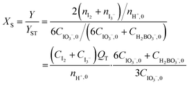 | (4) |
Here,
n is the molar flow rate,
C is the concentration,
QT is the total flow rate, and subscript 0 denotes the original reactant solutions. The platforms shown in
Fig. 1(d) and S6 of the ESI
† were used to test the mixing performance of the screw-tube mixers, a coiled tube, and a straight tube. The acid and base solutions were set to have identical flow rates during the experiments. The concentration of I
3− was measured with an in-line UV-vis spectrometer at 286 nm. (Other experimental details are provided in the ESI
†).
We first compared the variation of XS in the screw-tube mixer, the coiled tube mixer and the straight tube with the same ID of 0.75 mm. As a baseline, mixing in a 400 mm long straight tube is poor with a XS as high as 0.3, even when the flow rate increases (Fig. 4a). For the coiled tube with 32 mm loop diameter and the same length of the straight tube, better mixing performance is only observed when the total flow rate of acid and base solutions was above 0.8 mL min−1. At that point, the Dean vortices (Dean number De = 3.9) are strong enough to promote mixing.20 The screw-tube micromixer exhibits the best mixing performance, indicated by the smallest XS at any flow rate. The rotational flow induced by the screw pattern leads to cross-streamwise mixing even at low flow rates, which is desirable for flow chemistry studies with long residence times. We also compared the mixing performance in the screw-tube micromixers with different inner diameters (Fig. 1b, the original tube ID, d, is used to distinguish those mixers in the figure), and the results show that the smaller diameter tube give better mixing (Fig. 4b), although the depth of the screw pattern is relatively smaller.
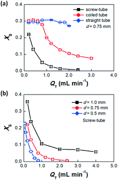 |
| | Fig. 4 Results of the Villermaux–Dushman reaction experiments. (a) Variation in XS with flow rate in a screw-tube mixer, a coiled tube mixer and a straight tube, whose ID or original ID before fabrication (labelled by d) is 0.75 mm. De is from 1.0 to 14.6 in the coiled tube. (b) Comparison of XS in 3 screw-tube mixers with different original IDs. QT is the total flow rate of the acid and base solutions. Error bars show the standard deviations for 3 parallel tests. Concentrations: CH+ = 0.02 mol L−1, CH2BO3− = 0.041 mol L−1, CI− = 0.02 mol L−1, and CIO3− = 0.0027 mol L−1 in all experiments. | |
RTD performance
Measurements of the residence time distribution (RTD) in the screw-tube mixer provides a second characterization of the cross-streamwise mixing in the system. The more cross-stream mixing the less the dispersion and the narrower RTD.21 We used an automated platform and the blue dye (Erioglaucine) in the above mixing experiment as a tracer to determine the RTDs for the screw-tube mixers (details are given in the ESI†). The RTDs were determined by deconvolution of the measured outputs from the system with and without the screw-tube micromixer in place by using a dispersion model with “open–open” boundary conditions (eqn (5)) in conjunction with a deconvolution algorithm.22| | 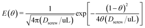 | (5) |
Here E(θ) is the dimensionless residence time distribution function; θ is equal to t/![[t with combining macron]](https://www.rsc.org/images/entities/i_char_0074_0304.gif) ; is the mean residence time;23Dscrew is the dispersion coefficient of the screw-tube micromixer; u is the mean velocity; and L is the mixer length.
; is the mean residence time;23Dscrew is the dispersion coefficient of the screw-tube micromixer; u is the mean velocity; and L is the mixer length.
Fig. 5(a) shows 3 groups of typical dimensionless RTD results of the screw-tube mixers with different diameters. In this test, the flow rates were kept constant at 1 mL min−1 in all three mixers, but the results indicate that the smaller diameter micromixer has larger dispersion coefficient. This may be attributed to the relatively shallower mixing pattern (Fig. 1b) in the tube inner surface, which leaded to slower rotation of fluid. However, the smaller diameter mixer also had better mixing, which is attributed to the shorter contact distance in the narrower tube mixers. Fig. 5(b) exhibits the dispersion coefficients in all three screw-tube mixers at different Re compared to the predicted dispersion coefficient by Taylor expression for the small and straight tube (eqn (6)).23
| | 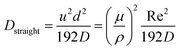 | (6) |
where
D is the diffusion coefficient of the tracer estimated by 1 × 10
−9 m
2 s
−1. All dispersion coefficients in the screw-tube mixers are smaller than the predicted valves for the straight tube, especially at Re > 20, indicating the strongly effect of the cross-stream mixing on narrowing the RTD. Therefore, both good mixing and excellent residence time control can be achieved using the screw-tube mixer.
 |
| | Fig. 5 RTD results and dispersion coefficients for the screw-tube mixers. (a) The dimensionless time distribution function in different diameter micromixers. Experiments were conducted at Q = 1 mL min−1. (b) dispersion coefficients at different Re and comparison to the predicted curve for the straight tube by using Taylor expression.23 Hydrodynamic diameters of 0.45, 0.65, 0.85 mm were used in Re calculation based upon their measured cross-section dimensions. Error bars show standard deviations in at least 3 parallel tests. | |
Gold nanoparticle synthesis
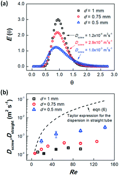
We further used synthesis of gold nanoparticles (Au-NPs) as a model system to evaluate the reaction enhancement performance of the designed screw-tube mixer.24,25 The Au-NPs were prepared by the reaction between HAuCl4 and NaBH4 with tetradecyltrimethylammonium bromide (TTAB) as ligands in the aqueous solution.26 Since the reducing reagent, NaBH4, can also be consumed by hydrolysis, the fast mixing between HAuCl4 and NaBH4 is important to obtain high yields of Au-NPs. Utilizing the platform shown in Fig. 1(d) and S9 of the ESI† with the same flow rate of NaBH4 and HAuCl4 + TTAB solutions, we compared the yields and particle size distribution of Au-NPs prepared with or without the micromixer (details of the experiments are provided in the ESI†). A higher UV-vis absorbance is observed (Fig. 6a) when the screw-mixer is applied, which indicates a higher yield of the particles. Fig. 6(b)–(d) illustrate the transmission electron microscopy (TEM, JEOL 2010) images of the Au-NPs and the statistical analysis of particle size distribution from at least 300 particles. We can conclude that the smaller particles are synthesized with better mixing. This reduced particle size is mainly a result of faster generation of Au0, which leads to higher concentration of seeds during the nucleation step.26,27 The average particle sizes (dpav) and the corresponding standard deviations (Std) are listed in Table 3.
 |
| | Fig. 6 Results of Au-NP synthesis experiments under following conditions: CHAlCl4 = 0.5 mmol L−1, CNaBH4 = 1.5 mmol L−1, CTTAB = 10.2 mmol L−1, QNaBH4 = QHAuCl4 = 0.4 mL min−1. (a) UV-vis spectra of Au-NP solutions. The height of the peek at 520 nm represents the concentration of the Au-NPs. (b–d) TEM images and particle size distributions from the experiments with and without and the screw-tube mixers (original tube IDs = 0.5 and 0.75 mm). The curvatures are fitted by normal distribution functions. | |
Table 3 Average sizes (dpav) and corresponding standard deviations (Std) of particles from TEM analysis
|
n
NaBH4/nHAuCl4(mol/mol) |
Original ID of the mixer (mm) |
dpav (nm) |
Std (nm) |
| 3.0 |
0.5 |
16.6 |
6.6 |
| 3.0 |
0.75 |
23.8 |
8.3 |
| 3.0 |
No mixer |
30.5 |
7.1 |
Conclusion
In order to obtain an effective fluoropolymer based in-line micromixer, we developed a thermoforming method to introduce screw patterns on commercial PFA, FEP and ETFE tubes that intensify cross-streamwise mixing in the tubes. This method is easy to implement and it is possible to obtain long mixers by repeated thermal forming. The mixing performance of the screw-tube micromixers was systematically investigated by dye tracing experiments, CFD simulations and the Villermaux–Dushman reaction experiments. Results indicated that the working mechanism of the screw-tube mixer is to generate rotating flow patterns in tubes, especially at Re > 20. RTD experiments further suggested reduced dispersion of the screw-tube micromixer compared to that of a straight tube owing to the cross-streamwise mixing. The screw-tube mixer was employed in the synthesis of Au-NPs by reaction between HAuCl4 and NaBH4. Higher yield as well as smaller size Au-NPs were obtained with the screw-tube mixers.
Conflicts of interest
The authors have no conflicts to declare.
Acknowledgements
We gratefully acknowledge the funding support from China Scholarship Council (201506215013) and the Novartis-MIT Centre for Continuous Manufacturing.
References
- J. C. Yang, D. Niu, B. P. Karsten, F. Lima and S. L. Buchwald, Angew. Chem., Int. Ed., 2016, 55, 2531–2535 CrossRef PubMed.
- S. Borukhova, T. Noël and V. Hessel, ChemSusChem, 2016, 9, 67–74 CrossRef PubMed.
- J. Yoshida, A. Nagaki, T. Iwasaki and S. Suga, Chem. Eng. Technol., 2005, 28, 259–266 CrossRef.
- L. Falk and J. M. Commenge, Chem. Eng. Sci., 2010, 65, 405–411 CrossRef.
- I. Vural Gürsel, S. K. Kurt, J. Aalders, Q. Wang, T. Noël, K. D. P. Nigam, N. Kockmann and V. Hessel, Chem. Eng. J., 2016, 283, 855–868 CrossRef.
- M. M. Mandal, P. Aggarwal and K. D. P. Nigam, Ind. Eng. Chem. Res., 2011, 50, 13230–13235 CrossRef.
- N. T. Nguyen and Z. G. Wu, J. Micromech. Microeng., 2005, 15, R1–R16 CrossRef.
- V. Hessel, H. Lowe and F. Schonfeld, Chem. Eng. Sci., 2005, 60, 2479–2501 CrossRef.
- J. Aubin, M. Ferrando and V. Jiricny, Chem. Eng. Sci., 2010, 65, 2065–2093 CrossRef.
- H. Song and R. F. Ismagilov, J. Am. Chem. Soc., 2003, 125, 14613–14619 CrossRef PubMed.
- A. Gunther, M. Jhunjhunwala, M. Thalmann, M. A. Schmidt and K. F. Jensen, Langmuir, 2005, 21, 1547–1555 CrossRef PubMed.
- A. D. Stroock, S. Dertinger, A. Ajdari, I. Mezic, H. A. Stone and G. M. Whitesides, Science, 2002, 295, 647–651 CrossRef PubMed.
- H. Chen and J. C. Meiners, Biophys. J., 2004, 86, 482A CrossRef.
- S. J. Park, J. K. Kim, J. Park, S. Chung, C. Chung and J. K. Chang, J. Micromech. Microeng., 2004, 14, 6–14 CrossRef.
- S. Schwolow, J. Hollmann, B. Schenkel and T. Röder, Org. Process Res. Dev., 2012, 16, 1513–1522 CrossRef.
- Y. Lü, S. Zhu, K. Wang and G. Luo, Chin. J. Chem. Eng., 2016, 24, 711–718 CrossRef.
- N. Baccar, R. Kieffer and C. Charcosset, Chem. Eng. J., 2009, 148, 517–524 CrossRef.
- J. S. Zhang, K. Wang, Y. C. Lu and G. S. Luo, Chem. Eng. Process., 2010, 49, 740–747 CrossRef.
- M. C. Fournier, L. Falk and J. Villermaux, Chem. Eng. Sci., 1996, 51, 5187–5192 CrossRef.
- M. Mansour, Z. Liu, G. Janiga, K. D. P. Nigam, K. Sundmacher, D. Thévenin and K. Zähringer, Chem. Eng. Sci., 2017, 172, 250–261 CrossRef.
- S. R. L. Gobert, S. Kuhn, L. Braeken and L. C. J. Thomassen, Org. Process Res. Dev., 2017, 21, 531–542 CrossRef.
- S. Kuhn, R. L. Hartman, M. Sultana, K. D. Nagy, S. Marre and K. F. Jensen, Langmuir, 2011, 27, 6519–6527 CrossRef PubMed.
-
O. Levenspiel, Chemical Reaction Engineering 3rd ed, John Wiley & Sons, New York, 1999 Search PubMed.
- S. E. Lohse, J. R. Eller, S. T. Sivapalan, M. R. Plews and C. J. Murphy, ACS Nano, 2013, 7, 4135–4150 CrossRef PubMed.
- A. Cirri, A. Silakov, L. Jensen and B. J. Lear, J. Am. Chem. Soc., 2016, 15987–15993 CrossRef PubMed.
- V. Sebastian Cabeza, S. Kuhn, A. A. Kulkarni and K. F. Jensen, Langmuir, 2012, 28, 7007–7013 CrossRef PubMed.
- X. Ji, X. Song, J. Li, Y. Bai, W. Yang and X. Peng, J. Am. Chem. Soc., 2007, 129, 13939–13948 CrossRef PubMed.
Footnote |
| † Electronic supplementary information (ESI) available: Fabrication details of micro-mixers, experimental set-up, simulation method, and additional experimental data. See DOI: 10.1039/c8re00112j |
|
| This journal is © The Royal Society of Chemistry 2018 |
Click here to see how this site uses Cookies. View our privacy policy here. 
 Open Access Article
 This Open Access Article is licensed under a
  *ab,
Haomiao
Zhang
*ab,
Haomiao
Zhang