DOI:
10.1039/C8RA09434A
(Paper)
RSC Adv., 2018,
8, 42017-42024
Sm-doped manganese-based Zr–Fe polymeric pillared interlayered montmorillonite for low temperature selective catalytic reduction of NOx by NH3 in metallurgical sintering flue gas
Received
15th November 2018
, Accepted 11th December 2018
First published on 18th December 2018
Abstract
In this work, Sm-doped manganese supported Zr–Fe polymeric pillared interlayered montmorillonites (Mn/ZrFe-PILMs) were prepared for the low-temperature selective catalytic reduction (SCR) of NOx with NH3 in metallurgical sintering flue gas. These pillared interlayered montmorillonite catalysts were characterized by X-ray diffraction, scanning electron microscopy and energy dispersive spectroscopy, nitrogen adsorption–desorption isotherm, ammonia temperature-programmed desorption, and hydrogen temperature-programmed reduction to study the influence of Sm doping on the SCR performance. The ZrFe-PILMs with a Mn/Sm molar ratio of 18![[thin space (1/6-em)]](https://www.rsc.org/images/entities/char_2009.gif) :2 showed the excellent SCR activity among these catalysts, where a 95.5% NOx conversion ratio at 200 °C at a space velocity of 20000 h−1 was obtained. Samarium oxide and manganese oxides were highly dispersed on the ZrFe-PILMs with different Mn/Sm molar ratios by the XRD results and SEM-EDS results. Meanwhile, the Mn–Sm/ZrFe-PILM (18:2) had the lowest temperature hydrogen reduction peak by H2-TPR results, which indicated that it had the lowest active bond energy on its surface. And the NH3-TPD results expressed that the Mn–Sm/ZrFe-PILM (18:2) had the most acidic sites, especially the weakly acidic sites. Therefore, it was found that the introduction of a small amount of Sm (Mn:Sm = 18:2) to Mn/ZrFe-PILM can significantly improve catalytic activity by the increased active oxygen component and the surface acidity.
:2 showed the excellent SCR activity among these catalysts, where a 95.5% NOx conversion ratio at 200 °C at a space velocity of 20000 h−1 was obtained. Samarium oxide and manganese oxides were highly dispersed on the ZrFe-PILMs with different Mn/Sm molar ratios by the XRD results and SEM-EDS results. Meanwhile, the Mn–Sm/ZrFe-PILM (18:2) had the lowest temperature hydrogen reduction peak by H2-TPR results, which indicated that it had the lowest active bond energy on its surface. And the NH3-TPD results expressed that the Mn–Sm/ZrFe-PILM (18:2) had the most acidic sites, especially the weakly acidic sites. Therefore, it was found that the introduction of a small amount of Sm (Mn:Sm = 18:2) to Mn/ZrFe-PILM can significantly improve catalytic activity by the increased active oxygen component and the surface acidity.
1. Introduction
NOx (NO, NO2) is a harmful air pollutant that causes many environmental issues, such as photochemical smog, acid rain, and the greenhouse effect. In addition, it can also cause harm to human health such as through respiratory and pulmonary disease.1 The large-scale application of the middle-temperature selective catalytic reduction (SCR) technology in coal-fired power plants has led to a sharp drop in their NOx emissions.2 On the other hand, NOx emissions of the iron and steel industry are still huge as an energy and pollution intensive manufacturing sector. The sinter plants are the main source of most gaseous pollutants (NOx, SO2, etc.).3,4 According to a China annual report on environment statistics in 2015,5 the NOx emissions of the iron and steel industry are still as high as 1.043 million tons each year, and NOx emissions are increasing year by year. The existing denitration technology for sintering flue gas is the circulating fluidized bed desulfurization–denitration technology and the activated carbon denitration technology. Although the fluidized bed desulfurization–denitration technology has a high SO2 removal efficiency, the NOx removal efficiency is low. And the activated carbon technology has high operating costs by consuming a large amount of activated carbon during the desorption of activated carbon. Based on the modification list of air pollutants emission standard for sintering and pelletizing of iron and steel industry (GB 28662-2012) in China,6 the demand of NOx emission standard will be raised to 100 mg m−3 in metallurgical sintering process. However, many sintering plants have not yet reached the emission standard. According to the National environmental statistics bulletin in 2015 in China, there are only 63 sets of deNOx equipment in 1522 sets of sintered pellets process of China. Therefore, studying a new deNOx method in metallurgical sintering flue gas is imperative. Sintering flue gas has the characteristics of low-temperature exhaust gas (120–180 °C), high oxygen concentration (15–18 vol%) and large flue gas volume. The method of low-temperature selective catalytic reduction of NOx with NH3 (NH3-SCR) is a heterogeneous catalytic reaction. Therefore, it can adapt the high smoke flow and complex smoke constituents of metallurgical sintering flue gas. This method can selectively convert NOx into non-polluting nitrogen in low temperature flue gas. Compared to the vanadium-based medium-temperature NH3-SCR method, it does not need to reheat a lot of low temperature flue gas to the temperature of 300–400 °C, which is energy efficient and economical. Therefore, the low temperature NH3-SCR method is believed to be the most promising denitration method in the future.
The low temperature SCR catalyst is the focus of research in low temperature NH3-SCR method.7 High performance SCR catalysts attract the attention of many researchers. Transition metals and rare earth metals are called research hotspots due to the characteristic of high performance and low cost. Manganese oxides have the best low temperature catalytic activity, but pure manganese oxides have disadvantages such as poor N2 selectivity and poor thermal stability.8 Some researchers aim to optimize and select high performance carrier (TiO2,9 Al2O3,10 SiO2,9 mesoporous silicon,11 activated carbon,12 semi-coke,13 titania nanotubes,14 Fe–Ti spinel,15 Mn–Ni–Ti tube16) because of their high specific surface area can facilitate uniform dispersion of manganese oxides and improve their thermal stability. In addition, the doping of the transition metal (Mn–Fe,17 Mn–Zr,18 Mn–Ni19) and the rare earth metal (Mn–Ce20,21) by the active component promotes the formation of more defects in the catalyst. And these defects will form various acid sites and weak linkages, which are beneficial to ammonia adsorption and activation in both Eley–Rideal and Langmuir–Hinshelwood mechanism.15 This study used the prepared zirconium and iron polymeric pillared interlayered montmorillonite as an acidic carrier which has the both a large specific surface area and a large amount of acid sites. Due to its unique physicochemical properties, it has been applied in many ways, such as Fisher–Tropsch,22 VOCs purification,23 photocatalysis Fenton,24 etc. And this is beneficial to improve the low temperature catalytic activity.25 This study used the high performance catalyst carrier to support the active components of Mn and Sm with different ratio (20:0, 18:2, 15:5, 10:10, 5:15, 0:20) to improve the catalytic activity. The characterization methods of XRD, SEM-EDS, NH3-TPD, H2-TPR, and liquid nitrogen adsorption method were used to investigate the structure and physicochemical properties of these catalysts.
2. Experimental
2.1 Catalyst preparation
The 98% pure Na montmorillonite (NaMt) was used as raw material for preparing metal pillared interlayered montmorillonite carrier. The ZrOCl2·8H2O (AR, Sinopharm), Fe(NO3)3·9H2O (AR, Sinopharm), and Na2CO3 (AR, Sinopharm) were used as precursors preparation material to hydrolyze to form metal oligomers for the montmorillonite pillared process. The Sm(NO3)3·6H2O and Mn(NO3)2 (50 wt% Mn(NO3)2 solution) were used as active component precursors. The NaMt chemical composition included SiO2 (60.28%), Al2O3 (20.97%), MgO (3.46%), Na2O (7.63%), CaO (0.38%), Fe2O3 (4.62%), K2O (0.63%), and TiO2 (0.51%). The NaMt ion exchange capacity was 120 meq./100 g.
Yamanaka S26 and Ilse Heylen27 studied the preparation method of Zr-PILM. This study had been improved on the basis of previous studies. The detailed preparation method of acidic carrier ZrFe-PILM can refer to the previous research.28 First, the zirconium pillaring agent and iron pillaring agent were prepared separately. The zirconium cations in 0.1 M ZrOCl2 precursor solution was hydrolyzed to zirconium oligomers at 80 °C and stirred for another 2 h. The 0.1 M Na2CO3 alkaline solution was added to the 0.1 M Fe(NO3)3 solution to promote hydrolysis of iron cations to iron oligomer cations and stirred for 4 h at room temperature. The molar ratio of Na2CO3 and Fe(NO3)3 was 1:1 and the stirred solution continues to age for 24 h at room temperature to form iron pillaring agent. After that, the mixed pillaring agent of zirconium and iron was prepared by the molar ratio of Zr/Fe = 1:3 and stirred vigorously at room temperature for another 3 h. Then, the zirconium iron mixed pillaring agent were added to the 1 wt% NaMt slurry. The metal cations and NaMT molar ratio was (Zr + Fe)/NaMt = 10 mmol g−1. Then the mixed suspensions were stirred at 60 °C for another 3 h. The mixed suspension was centrifuged and washed for five times. At last, the ZrFe-PILM carrier was obtained by dried at 90 °C for 24 h and calcined at 400 °C for 3 h.
Different molar ratios of Mn and Sm (Mn/Sm = 20:0, 18:2, 15:5, 10:10, 5:15, 0:20) were impregnated into the ZrFe-PILM carrier with 10 wt% of the catalyst. Then the impregnated wet samples were dried at 90 °C for 24 h and calcined at 400 °C for 3 h with 5 °C min−1 heating rate under air condition. The catalyst expression form was Mn–Sm/ZrFe-PILM (A:B) and the A:B represents the molar ratio of Mn to Sm. The catalyst preparation process visualization flow chart is shown in Fig. 1.
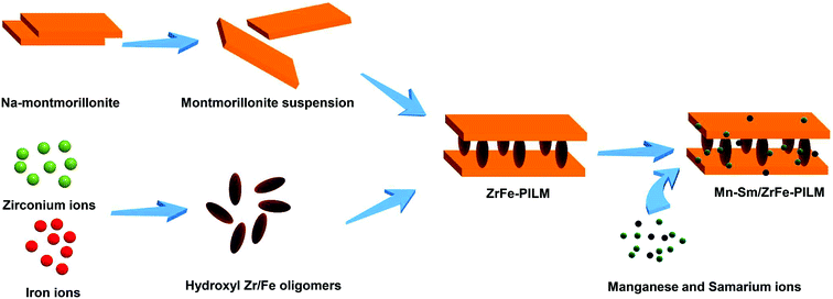 |
| | Fig. 1 Catalyst preparation process visual flow chart. | |
2.2 Catalyst characterization
The shimadzu XRD 7000 diffractometer was used to detect the X-ray spectrum of these catalysts with the Cu Kα radiation. The XRD scan speed was 2 deg min−1, and the scanning angles was from 10 to 70°.
Element content was recorded by a Rigaku ZSX100E analyzer with a Pd anode as the X-ray source and F-PC and SC detector.
The surface morphology and surface element distribution of Mn–Sm/ZrFe-PILM catalysts were detected by scanning electron microscope and energy dispersive spectrometer (SEM-EDS) (Ultra Plus, Carl Zeiss AG).
The Quantachrome physical adsorption instrument was used to record N2 adsorption–desorption isotherm curve at −196 °C. The specific surface area, total pore volume and pore size distribution of the sample can be calculated from the N2 adsorption–desorption isotherm. The catalyst samples need to be dried at 200 °C for 3 h before testing. The specific surface area of these catalysts was calculated by Brunauer–Emmett–Teller (BET) method at the relative pressure P/P0 between 0.05 to 0.2. The total pore volume (VTPD) was obtained from the N2 adsorption capacity at the relative pressure P/P0 = 0.98. The average pore sizes (D) of these catalysts can be calculated by the formula below: D = 4VTPD/SBET. And the pore size distribution can be calculated by the Barrett–Joyner–Halenda (BJH) method.
The curves of ammonia temperature-programmed desorption (NH3-TPD) can be recorded by a thermal conductivity detector (TCD) of Tianjin XQ TP5080 automatic adsorption instrument. First, a quartz tube was added with 100 mg of catalyst sample and purged at 30 mL min−1 at 200 °C for 30 min in a helium atmosphere to remove catalyst adsorbed impurity. The heating rate from room temperature to 200 °C is 10 °C min−1. Then the quartz tube heating furnace was cooled down to 50 °C and begins to pass pure ammonia for 30 min with the flow of 30 mL min−1. The catalyst was purged with 30 mL min−1 of helium for 1 h to 2 h to remove the physically adsorbed ammonia. Finally, the catalyst was heated to 550 °C with the heating rate of 5 °C min−1 and the catalyst NH3-TPD curves was obtained.
The curves of temperature-programmed reduction by H2 (H2-TPR) can be recorded by a Tianjin XQ TP5080 chemisorption analyzer instrument. First, a 20 mg sample catalyst was placed in a quartz tube furnace and heated from room temperature to 200 °C with rate of 10 °C min−1 for pretreatment. And the catalyst sample was purged at 50 mL min−1 helium for 30 min at 200 °C. The sample was then cooled to 50 °C and passed through a mixture of 5% H2 + He at 50 mL min−1 for 30 min to be stabilized at baseline. The sample was desorbed to a temperature of 800 °C at a heating rate of 5 °C min−1 in a 5% H2 + He gas stream, and the evolved gas was detected by a thermal conductivity detector (TCD).
2.3 Catalytic activity test
The catalytic detection system was divided into a gas distribution system, a catalytic activity detection system and a gas detection system. The simulated flue gas was composed of NO (500 ppm), NH3 (500 ppm), O2 (15 vol%) and balance gas argon. The gas flow rate and volumetric space velocity were 300 mL min−1 and 20000 h−1 respectively. The formulated NH3 and NO were standard gases of 5% NH3 in Ar and 5% NO in Ar, respectively. In addition, both Ar and O2 were high purity gases. These gases were supplied by Dalian Airichem Specialty Gases & Chemicals Co. Ltd. Use a heating belt to heat from the premixed gas tank and keep it at 120 °C to prevent precipitation of ammonium nitrate precipitation. Catalytic activity was measured in a steady flow mode in a quartz tube fixed bed reactor (i.d. = 10 mm). Catalytic reaction temperature increased from 120–200 °C at intervals 20 °C. Each temperature point was kept for 30 min to achieve a balanced reaction gas concentration. In the detection system, Gasmet DX4000 FT-IR gas analyzer (Gasmet Technologies Inc.) was used to detect the gas concentrations of NO, NO2, NH3 and N2O in the outlet gas. The evaluation index of catalytic activity was NOx conversion and N2 selectivity. Then its calculation equation was as follows:| |
 | (1) |
| |
 | (2) |
where [NOx] was the sum of [NO] and [NO2], and [NOx]in, [NOx]out, [NH3]in, [N2O]out were the corresponding outlet and inlet gas concentrations.
3. Results and discussion
3.1 Catalyst phase composition and active component distribution
In order to accurately understand the content of Mn and Sm content and molar ratio. The actual weight contents of Mn and Sm in the Mn–Sm/ZrFe-PILM catalysts and its ratios are shown in Table 1. It can be seen that the actual molar ratio of Mn:Sm is similar to the molar ratio at the time of preparation. The actual molar ratio of Mn:Sm were 8.31, 3.06, 1.14, and 0.37. In order to better observe the dispersibility of the catalyst, XRD and SEM-EDS were used to observe the dispersibility of the active components Mn and Sm on the catalyst surface.
Table 1 Catalysts Mn and Sm element content and its molar ratio
| Catalysts |
Mn content (wt%) |
Sm content (wt%) |
Mn:Sm molar ratio |
| Mn/ZrFe-PILM |
6.65 |
— |
— |
| Mn–Sm/ZrFe-PILM (18:2) |
6.25 |
2.09 |
8.31 |
| Mn–Sm/ZrFe-PILM (15:5) |
4.84 |
4.40 |
3.06 |
| Mn–Sm/ZrFe-PILM (10:10) |
3.21 |
7.82 |
1.14 |
| Mn–Sm/ZrFe-PILM (5:15) |
1.56 |
11.6 |
0.37 |
| Sm/ZrFe-PILM |
— |
13.7 |
— |
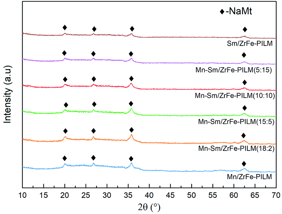
The XRD patterns of Mn–Sm/ZrFe-PILM catalysts with different Mn/Sm molar ratio (20:0, 18:2, 15:5, 10:10, 5:15, 0:20) are shown in Fig. 2. The NaMt crystalline phase peaks were shown at 20.2°, 26.8°, 35.5°, and 50.6°, which correspond to NaMt phase. These catalysts all had NaMt characteristic peaks. But the crystalline phase peaks of intercalated ZrO2 and Fe2O3 were not found. This was because that the iron and zirconium polymerized oligomers were exchanged to the pillared interlayered montmorillonite layer with suitable molar ratio of Zr/Fe = 1:3. The polymerized pillared montmorillonite not only enhanced the pore size structure of the catalyst, but also promoted uniform dispersion of ZrO2 and Fe2O3. And the ZrO2 and Fe2O3 had a low crystallinity in pillared montmorillonite. And the detailed reasons can refer to the previous study.28 Similarly, the crystalline spectra peaks of manganese oxides and samarium oxides were also not found. It was because that manganese oxides and samarium oxides were highly dispersed into the Zr–Fe polymeric pillared interlayered montmorillonite carrier. And this was also consistent with the results of SEM-EDS results in Fig. 3.
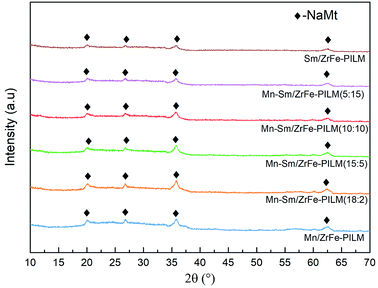 |
| | Fig. 2 Powder X-ray diffraction patterns of Mn–Sm/ZrFe-PILM with various Mn/Sm molar ratio (20:0, 18:2, 15:5, 10:10, 5:15,0:20). | |
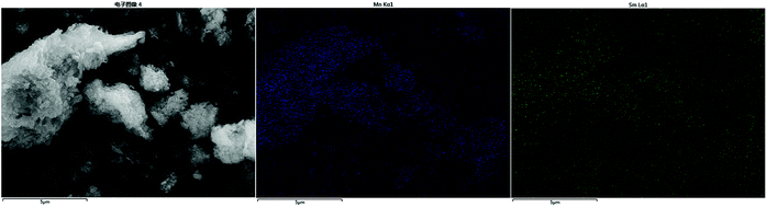 |
| | Fig. 3 Surface morphology of Mn–Sm/ZrFe-PILM (18:2) and energy dispersive spectrometer of Mn element and Sm element. | |
3.2 Morphology and texture
The surface morphology of ZrFe-PILM (A) carrier and Mn–Sm/ZrFe-PILM (18:2) (B) catalyst are shown in the Fig. 4. Scanning electron microscopy images of the catalysts were magnified at 10000 times. The ZrFe-PILM carrier and Mn–Sm/ZrFe-PILM catalyst had a rough surface and a porous surface structure. The carrier of ZrFe-PILM had a specific surface area of 176.2 m2 g−1, and the specific surface area was greatly improved compared to the raw materials Na montmorillonite (13.69 m2 g−1). The specific surface area of Mn–Sm/ZrFe-PILM (18:2) drops to 102.5 m2 g−1 compared to carrier ZrFe-PILM. This may be due to the fact that the active components Mn and Sm carry the carrier and occupy some of the pore size of the support. Therefore, a large number of pore structures facilitated the loading and uniform dispersion of the active components.
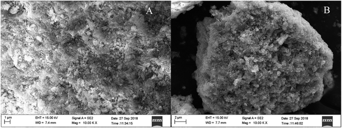 |
| | Fig. 4 The scanning electron microscope morphology of ZrFe-PILM carrier (A) and Mn–Sm/ZrFe-PILM (18:2) (B) catalyst at 20000 times. | |
The detailed aperture type and pore size distribution can be seen from Fig. 5. The ZrFe-PILM carrier and Mn–Sm/ZrFe-PILM (18:2) catalyst had a similar N2 adsorption desorption isotherm shapes. And based on the International Union of Pure and Applied Chemistry (IUPAC), the adsorption and desorption curves of ZrFe-PILM and Mn–Sm/ZrFe-PILM (18:2) belonged to the type of IV. It indicated that the aperture type of ZrFe-PILM and Mn–Sm/ZrFe-PILM (18:2) were mainly mesoporous. The hysteresis loop of the N2 adsorption desorption isotherm belonged to the H3 type. This type of hysteresis loop represented the mesopores of the slits or crack shape pores. This is because the mixed oligomer of zirconium and iron entered the montmorillonite layer and supported the montmorillonite layer. Since the carrier and catalyst were mesoporous structure, the BJH method was used to calculate the pore size distribution. As can be seen from the pore size distribution of Fig. 4, the pore sizes of ZrFe-PILM and Mn–Sm/ZrFe-PILM were concentrated at 1.91 nm and 1.92 nm, respectively. The higher specific surface area and smaller pore structure provided more reaction and adsorption platforms for the reactants in the SCR reaction.
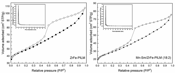 |
| | Fig. 5 The BJH pore size distribution and adsorption desorption isotherm of N2 at −196 °C for ZrFe-PILM carrier and Mn–Sm/ZrFe-PILM (18:2). | |
3.3 Catalyst surface acidity
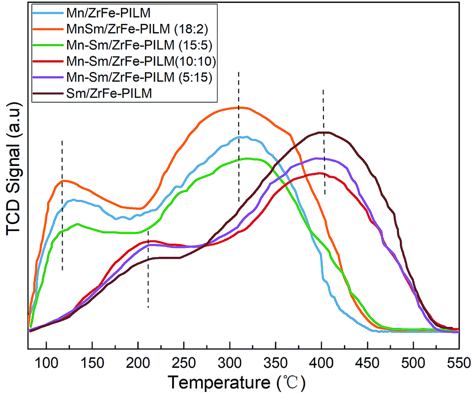
The nature of acidic sites of the Mn–Sm/ZrFe-PILM catalysts with different Mn/Sm molar ratio were determined by ammonia temperature programmed desorption (NH3-TPD) technique. The NH3-TPD patterns collected are illustrated in Fig. 6. These catalysts exhibited primarily two ammonia desorption peaks in the temperature range from 80 °C to 550 °C. The peaks that appeared at low temperatures were ascribed to ammonia bound to weak acidic sites. And the peaks at higher temperatures attributed to strong acidic sites for ammonia adsorption. When the molar ratio of Mn/Sm was 20:0, 18:2, and 15:5, the ammonia desorption peaks were at a lower temperature around 120 °C and 300 °C. When the ratio of Mn/Sm was 10:10, 15:5, and 20:0, the ammonia desorption peaks were at a higher temperature around 200 °C and 400 °C. It was established that the acidic site distribution can broaden by the addition of small amount of Sm. The Mn–Sm/ZrFe-PILM (18:2) had the most acidic sites, especially the weak acidic sites. And it exhibited a larger peak centered at 117 °C which can be attributed to the desorption of ammonia coordinated on weak acid sites. In general, the weak acid sites belonged to the Lewis acid sites on the surface of the catalyst. A large amount of Lewis acid sites was beneficial to the adsorption of ammonia. Based on the principle of Langmuir–Hinshelwood and Eley–Rideal mechanism, this enhancement in ammonia adsorption or activation will increase reaction rate and promote selective catalytic reduction activity. This was also in good agreement with the activity experiments in the catalytic activity.
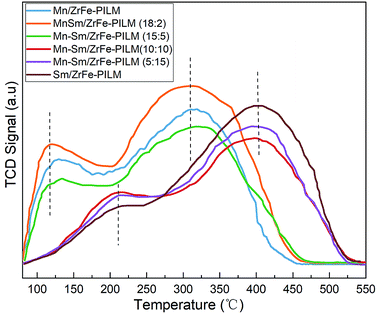 |
| | Fig. 6 NH3-TPD patterns of Mn–Sm/ZrFe-PILM with different Mn/Sm molar ratio (Mn/Sm = 20:0, 18:2, 15:5, 10:10, 5:15, 0:20). | |
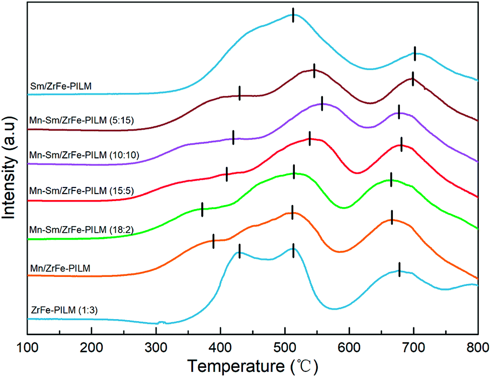
3.4 Catalyst reduction property
In the low temperature SCR reaction, the redox properties of the catalyst played an important role in the activity of the catalyst. The reduction profiles for carrier ZrFe-PILM and Mn–Sm/ZrFe-PILM catalysts with various ratio Mn/Sm (Mn/Sm = 20:0, 18:2, 15:5, 10:10, 5:15, and 0:20) were determined by hydrogen temperature programmed reduction (H2-TPR). The H2-TPR patterns collected are shown in the Fig. 7. The hydrogen reduction peak temperature represented the magnitude of the bond energy of the active component on the surface of the catalyst. The hydrogen reduction peak in low temperature represented a low bond energy of the active component of the catalyst, and the hydrogen reduction peak in high-temperature represented a high bond energy of the active components of the catalyst. The carrier ZrFe-PILM and catalyst Mn–Sm/ZrFe-PILM with various Mn/Sm molar ratio, expect Sm/ZrFe-PILM, had three hydrogen reduction peaks in the temperature range of 350–450 °C,500–550 °C and 650–700 °C, respectively. The Mn–Sm/ZrFe-PILM (18:2) catalyst hydrogen desorption curve contained the lowest temperature hydrogen reduction peak, which means that the bond energy of the active component of the catalyst was minimal compared to other Mn/Sm molar ratios of the catalyst. And the Mn–Sm/ZrFe-PILM (18:2) catalyst had the highest catalytic activity. This maybe due to the low energy bond on the active catalyst surface and the large amount of active oxygen components, which was beneficial to the low temperature catalytic activity. The carrier ZrFe-PILM had a higher temperature reduction peak. Therefore, the active component Mn and Sm reduce the low temperature reduction peak after supporting the carrier, which is beneficial to increase the low temperature catalytic activity. The temperature of the low temperature reduction peak of hydrogen was consistent with the low temperature catalytic activity of the catalyst. And its reduction peak temperature was lower, its catalytic activity was higher.
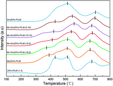 |
| | Fig. 7 Influence of various ratio Mn/Sm on the hydrogen temperature-programmed reduction (H2-TPR) patterns of Mn–Sm/ZrFe-PILM catalysts. | |
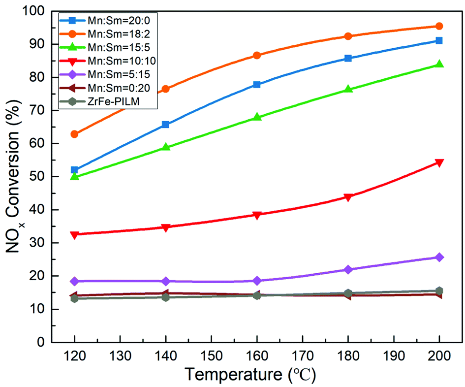
3.5 Catalyst activity
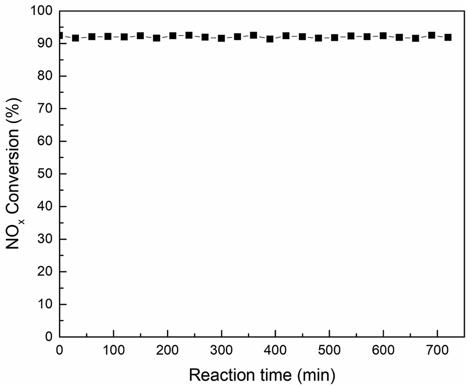
The NOx conversion of Mn–Sm/ZrFe-PILM catalysts with different molar ratios of Mn and Sm and carrier ZrFe-PILM are shown in Fig. 8. The NOx conversion of these catalysts was increased with increasing temperature from 120 °C to 200 °C. The active component Sm loaded onto the ZrFe-PILM carrier and the carrier ZrFe-PILM had the lowest NOx conversion with around 14% from 120–200 °C reaction temperature. The NOx conversion of Mn/ZrFe-PILM was increased from 52.0% to 91.1% in the temperature range from 120 °C to 200 °C. Interestingly, when a small amount of Sm doped into the active component Mn (Mn:Sm = 18:2), its catalytic activity was improved from 120 °C to 200 °C. It had the largest NOx conversion with 95.5% NOx conversion at 200 °C. However, when the molar ratio of Sm increased, the catalytic activity decreased. This may be due to the fact that a small amount of samarium oxides doped into manganese oxides can increase a large number of defect sites. These defect sites form more acidic sites and a large amount of active oxygen. The ammonia adsorption and activation were increased in the SCR reaction. It was an important step in the reaction mechanism of Eley–Rideal and Langmuir–Hinshelwood mechanism. This was also the root cause of the increase in catalytic activity. However, the increase in catalytic activity of the trace Sm-doped Mn also reduced the N2 selectivity of the catalyst, as it is shown in Fig. 9. This was because the introduction of the samarium does not inhibit the excessive activation of ammonia, resulting in an increase in side reactions that produce N2O. Although the Mn–Sm/ZrFe-PILM (18:2) catalyst had the lowest N2 selectivity compared to other catalysts. However, its N2 selectivity was greater than 85% between 120 and 200 °C. This was because ZrFe-PILM acts as an acidic carrier for the active component, inhibiting partial ammonia overactivation, thereby increasing the N2 selectivity of the catalyst.29 Then, the catalyst Mn–Sm/ZrFe-PILM (18:2) was tested at 180 °C in the activity detection system for 720 min to assess whether the catalyst would be deactivation for a long time. The activity test results were shown in Fig. 10. It can be seen from the test data in the figure that the activity of the catalyst was stable above 91% after a test of up to 720 min. This means that the Mn–Sm/ZrFe-PILM not only had good catalytic activity, but also had long activity stability. This was beneficial to the catalyst to remove NOx in the flue gas for a long time, thereby reducing the cost of operation.
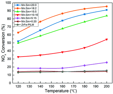 |
| | Fig. 8 Effect on NOx conversion in the SCR reaction of Mn–Sm/ZrFe-PILM catalyst with respect to the Mn/Sm molar ratio (GHSV = 20000 h−1; feed: NO = 500 ppm, NH3 = 500 ppm, O2 = 15 vol%, Ar carrier gas). | |
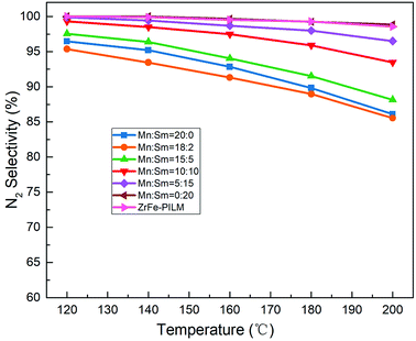 |
| | Fig. 9 Effect on N2 selectivity in the SCR reaction of Mn–Sm/ZrFe-PILM catalyst with respect to the Mn/Sm molar ratio (GHSV = 20000 h−1; feed: NO = 500 ppm, NH3 = 500 ppm, O2 = 15 vol%, Ar carrier gas). | |
 |
| | Fig. 10 The stability test of Mn–Sm/ZrFe-PILM (18:2) catalyst at 180 °C (GHSV = 20000 h−1; feed: NO = 500 ppm, NH3 = 500 ppm, O2 = 15 vol%, Ar carrier gas). | |
4. Conclusions
A series of Mn–Sm/ZrFe-PILM catalysts with different molar ratios of Mn/Sm (Mn:Sm = 20:0, 18:2, 15:5, 10:10, 5:15, 0:20) were prepared and studied. The results showed that a small amount of samarium doping (Mn:Sm = 18:2) was beneficial to improve the low temperature catalytic activity of the catalyst Mn–Sm/ZrFe-PILM. The NOx conversion rate reached 95.5% at 200 °C. XRD and SEM results showed that the active components manganese and samarium oxides were highly dispersed on the surface of the mesoporous support ZrFe-PILM. Highly dispersed active components provided more reaction platform for catalytic reactions. The NH3-TPD results indicated that the Mn–Sm/ZrFe-PILM (18:2) catalyst had the most weakly Lewis acid sites. Lewis acid promoted the adsorption of ammonia in the Langmuir–Hinshelwood and Eley–Rideal mechanisms. Therefore, the low temperature catalytic activity of the catalyst was promoted. In addition, the addition of samarium reduced the bond energy of the Mn/ZrFe-PILM catalyst, and Mn–Sm/ZrFe-PILM (18:2) had the lowest bond energy according to the H2-TPR pattern. Therefore, when trace amount of samarium was doped with Mn/ZrFe-PILM, the low-temperature catalytic activity of the catalyst was improved. Compared with other catalytic systems, this study mainly used the prepared high specific surface area acidic carrier to promote the adsorption of ammonia and nitrogen oxides. The active component loading and doping facilitates the redox reaction between the support and the active component,15 thereby promoting the activity of the catalyst.
Conflicts of interest
There are no conflicts to declare.
Acknowledgements
This research was supported by the Major State Research Development Program of China (2017YFB0603603) and National Natural Science Foundation of China (51576035).
References
- J. M. Vincent, Australas. Radiol., 2002, 46, 139 CrossRef.
- Z. Li, J. Jiang, Z. Ma, S. Wang and L. Duan, Atmos. Environ., 2015, 120, 227–233 CrossRef CAS.
- K. Wang, H. Tian, S. Hua, C. Zhu, J. Gao, Y. Xue, J. Hao, Y. Wang and J. Zhou, Sci. Total Environ., 2016, 559, 7–14 CrossRef CAS PubMed.
- J. Han, X. He, L. Qin, W. Chen and F. Yu, Ironmaking Steelmaking, 2014, 41, 350–354 CrossRef CAS.
- Ministry of Ecology and Environment of the People's Republic of China, Emission standard of air pollutants for sintering and pelletizing of iron and steel industry, China Environmental Science Press, 2015 Search PubMed.
- Ministry of Ecology and Environment of the People's Republic of China, Amendment sheet for iron and steel sintering and pellet industry air pollutant emission standards, China Environmental Science Press, 2017 Search PubMed.
- J. Li, H. Chang, L. Ma, J. Hao and R. T. Yang, Catal. Today, 2011, 175, 147–156 CrossRef CAS.
- F. Kapteijn, L. Singoredjo and A. Andreim, Appl. Catal., B, 1994, 3, 173–189 CrossRef CAS.
- P. G. Smirniotis, D. A. Peña and B. S. Uphade, Angew. Chem., Int. Ed., 2001, 40, 2479–2482 CrossRef CAS PubMed.
- L. Qu, C. Li, G. Zeng, M. Zhang, M. Fu, J. Ma, F. Zhan and D. Luo, Chem. Eng. J., 2014, 242, 76–85 CrossRef CAS.
- J. Huang, Z. Tong, Y. Huang and J. Zhang, Appl. Catal., B, 2008, 78, 309–314 CrossRef CAS.
- Y. Wang, X. Li, L. Zhan, C. Li, W. Qiao and L. Ling, Ind. Eng. Chem. Res., 2015, 54, 2274–2278 CrossRef CAS.
- Y. Chen, Z. Zhang, L. Liu, L. Mi and X. Wang, Appl. Surf. Sci., 2016, 366, 139–147 CrossRef CAS.
- T. Boningari, D. K. Pappas and P. G. Smirniotis, J. Catal., 2018, 365, 320–333 CrossRef CAS.
- S. Yang, F. Qi, S. Xiong, H. Dang, Y. Liao, P. K. Wong and J. Li, Appl. Catal., B, 2016, 181, 570–580 CrossRef CAS.
- J. Liu, X. Li, R. Li, Q. Zhao, J. Ke, H. Xiao, L. Wang, S. Liu, M. Tadé and S. Wang, Appl. Catal., A, 2018, 549, 289–301 CrossRef CAS.
- F. Liu, H. He, Y. Ding and C. Zhang, Appl. Catal., B, 2009, 93, 194–204 CrossRef CAS.
- J. Zuo, Z. Chen, F. Wang, Y. Yu, L. Wang and X. Li, Ind. Eng. Chem. Res., 2014, 53, 2647–2655 CrossRef CAS.
- B. Thirupathi and P. G. Smirniotis, Appl. Catal., B, 2011, 110, 195–206 CrossRef CAS.
- G. Qi, R. T. Yang and R. Chang, Appl. Catal., B, 2004, 51, 93–106 CrossRef CAS.
- S. Andreoli, F. A. Deorsola and R. Pirone, Catal. Today, 2015, 253, 199–206 CrossRef CAS.
- N. Ahmad, S. T. Hussain, B. Muhammad, N. Ali, S. M. Abbas and Z. Ali, Prog. Nat. Sci.: Mater. Int., 2013, 23, 374–381 CrossRef.
- M. Chen, L. Qi, L. Fan, R. Zhou and X. Zheng, Mater. Lett., 2008, 62, 3646–3648 CrossRef CAS.
- J. Gao, L. Wu, S. Liang, S. Zhang, P. Liu and X. Fu, Chin. J. Catal., 2010, 31, 317–321 CAS.
- Z. Han, Q. Yu, H. Xie, K. Liu, Q. Qin and Z. Xue, Environ. Sci. Pollut. Res., 2018, 25, 32122–32129 CrossRef CAS PubMed.
- S. Yamanaka and G. W. Brindley, Clays Clay Miner., 1979, 27, 119–124 CrossRef CAS.
- I. Heylen, N. Maes, P. Cool, M. De Bock and E. F. Vansant, J. Porous Mater., 1996, 3, 217–225 CrossRef CAS.
- H. Zhicheng, Y. Qingbo, X. Huaqing, L. Kaijie, Q. Qin and X. Zhijia, Environ. Sci. Pollut. Res., 2018, 25, 32122–32129 CrossRef PubMed.
- R. Camposeco, S. Castillo, I. Mejia-Centeno, J. Navarrete and V. Rodriguez-Gonzalez, Microporous Mesoporous Mater., 2016, 236, 235–243 CrossRef CAS.
|
| This journal is © The Royal Society of Chemistry 2018 |
Click here to see how this site uses Cookies. View our privacy policy here. 
 Open Access Article
 This Open Access Article is licensed under a Creative Commons Attribution-Non Commercial 3.0 Unported Licence
 a,
Qingbo Yu*a,
Zhijia Xueab,
Kaijie Liu
a,
Qingbo Yu*a,
Zhijia Xueab,
Kaijie Liu