
 Open Access Article
 This Open Access Article is licensed under a Creative Commons Attribution-Non Commercial 3.0 Unported Licence
High-performance yttrium-iron alloy doped Pt-free catalysts on graphene for hydrogen evolution
Pengcheng Zhu abc,
Dandan Lyuabc and
Pei Kang Shen*abc
abc,
Dandan Lyuabc and
Pei Kang Shen*abc
aCollaborative Innovation Center of Sustainable Energy Materials, Guangxi University, Nanning, 530004, P. R. China
bGuangxi Key Laboratory of Electrochemical Energy Materials, Guangxi University, Nanning, 530004, P. R. China
cState Key Laboratory of Processing for Non-ferrous Metal and Featured Materials, Guangxi University, Nanning, 530004, P. R. China. E-mail: pkshen@gxu.edu.cn
First published on 6th December 2018
Abstract
Research into the preparation and application of metal/graphene nanocomposite materials is an important issue in the field of graphene applications. Metal nanomaterials and graphene materials have many excellent properties and have been perfectly combined into metal/graphene nanocomposite materials. These offer the high catalytic activity of metal nanomaterials and the high specific surface area and favorable electrical conductivity of graphene. The unique advantages can produce synergistic effects and can significantly improve the overall performance of the composite materials. This gives the metal/graphene nanocomposite materials excellent application prospects for hydrogen evolution. Here, we report the preparation of yttrium-doped palladium/iron on graphene (Pd/YFeO3/GC) using a simple and efficient method. The catalytic performance of the Pd/YFeO3/GC nanocomposites for water electrolysis and hydrogen production was evaluated. The results show that the overpotential for the hydrogen evolution reaction at −10 mA cm−2 is only 15 mV, which is competitive with Pt/C catalysts. The Pd/YFeO3/GC is highly active for hydrogen evolution with an onset potential of −8 mV in 0.5 M H2SO4 solution and a Tafel slope of 37 mV dec−1 with a Pd loading of only 20 μgPd cm−2. These results clearly demonstrated that Pd/YFeO3/GC is an excellent catalyst for hydrogen evolution.
1 Introduction
Clean and sustainable alternative energy sources are needed to combat environmental pollution and depletion of fossil fuels.1 Hydrogen is environmentally friendly and can offer high energy. Hence, hydrogen energy sources—thought to be the most ideal clean energy source of the 21st century—are actively researched.2,3 Water electrolysis is an important way to realize the cheap preparation of hydrogen. It is an effective approach to solve today's increasingly serious energy challenges.4 Hydrogen can be produced via water electrolysis, whereby a catalyst accelerates the electrochemical reactions of the anode and the cathode. Thus, a highly active catalyst can guarantee the hydrogen evolution reaction (HER).HER catalysts are currently composed of precious metals such as Pt and Pd.5–8 In practice, hydrogen production by large-scale electrochemical method is usually constrained by two main problems: (1) main dependence on the noble metal platinum and (2) poor stability of the catalyst materials under the strongly acidic conditions of PEMF cells. Thus, there need a highly active catalyst to promote the HER. Recently, research great efforts are ongoing to find suitable HER catalysts based on more economical non-precious metal materials such as Ni, Mo, W, and other transition-metal-based electrocatalysts.9–15 However, compared with precious metals, the catalytic performance of non-precious metals is not good enough. Precious metal catalysts offer high catalytic performance, low overpotential, and good stability, but they also have a low utilization rate (less than 20% of the Pt catalyst is used),16,17 Precious metals are also expensive and rare, making the bulk preparation of precious metal catalysts challenging. Therefore, research into low-cost and high-efficiency non-precious metal catalysts is an active research topic, despite their lower performance. While the hydrogen evolution performance of non-precious metal catalysts is similar to platinum when placed on carbon,12,14,18–20 the catalyst preparation process is cumbersome and complicated by poor reproducibility.
Here, using the features of successful catalysts, we prepared a palladium catalyst prepared from rare earth elements and graphene (Pd is cheaper than Pt). We doped palladium into iron and yttrium on a graphene catalyst (Pd/YFeO3/GC) for hydrogen evolution. Compared with non-precious metals, the preparation of Pd catalyst is simple and reproducible. The results show that the overpotential of the HER at −10 mA cm−2 is only 15 mV, which is can competitive with the Pt/C catalyst. The Pd/YFeO3/GC is highly active for HER with am onset potential of −8 mV in 0.5 M H2SO4, the Tafel slope is 37 mV dec−1 at a Pd-loading of only 20 μgPd cm−2. These results clearly demonstrated that Pd/YFeO3/GC is an excellent catalyst for hydrogen evolution.
2 Experimental
2.1 Materials
Palladium chloride 99.0% (PdCl2), iron(III) chloride hexahydrate 99.0% (FeCl3·6H2O), yttrium(III) nitrate hexahydrate 99.5% and potassium hydroxide 85.0% (KOH) were provided by Guangdong Guanghua Sci-Tech Co., Ltd. Graphene were provided by Collaborative Innovation Center of Renewable Energy Materials in Guangxi University.2.2 Catalyst preparation
The graphene was pretreated in HNO3 (3 M) with stirring for 2 h followed by addition of H2SO4. The samples were continually stirred and heated at 80 °C for 6 h in an oil bath. Finally, the solution was filtered using a microfiltration membrane (diameter 50 mm, microporosity 0.5 μm) and washed many times with deionized water. This was then dried at 50 °C for 6 h in a vacuum oven.A liquid metal reduction method was used to prepare catalyst nanocomposite materials. First, 0.2 g of pretreated graphene was dispersed in dimethylformamide and ultrasonicated for 6 h in an ultrasonic bath (HN-500A). The 0.12 g of YN3O9·6H2O and 0.08 g of FeCl3·6H2O were dissolved in 25 mL deionized water and added to the dispersed graphene followed by ultrasonication for 6 h. Finally, 2.2 mL of dissolved PdCl2 (10 mg mL−1) was added dropwise to the mixed solution and continually ultrasonicated for 6 h; the solution was filtered using a microfiltration membrane (diameter 50 mm, microporosity 0.5 μm). This was washed several times with deionized water and then dried at 50 °C for 6 h in a vacuum oven. After grinding, the powders were calcined at 800 °C for 2 h in a tube furnace under a pure nitrogen flow.
2.3 Catalyst characterization
The Raman spectra were obtained by a Raman spectrometer (Horiba, LabRAM HR Evolution) using a TE air-cooled 576 × 400 CCD array in a confocal Raman system with a laser wavelength of 532 nm. An X-ray diffractometer (XRD, SmartLab) with Cu-Kα radiation was used for catalyst structure analysis from 10° to 90°. Scanning electron microscopy (SEM, SU8220) and transmission electron microscopy (TEM, Titan ETEM G2 80-300) were used to study the catalyst morphology and calculate the size and lattice parameters of the precious metals and metal oxide particles. The Brunauer–Emmett–Teller (BET, ASAP 2460) method was used to measure the surface area of the catalyst. X-ray photoelectron spectroscopy (XPS, Kratos Axis Ultra-DLD) with 1486.6 eV Al-Kα as an excitation source was used to analyze the chemical composition and elemental chemical binding of the samples.2.4 Electrochemical characterization
Electrochemical characterization used cyclic voltammetry (CV) and linear sweep voltammetry (LSV). These were performed with a potentiostat and a rotating ring disk electrode (RRDE) system (PINE) in a conventional three-electrode cell. The test system contained a carbon electrode as the counter electrode, a reversible hydrogen electrode (RHE) as the reference electrode, and a rotating disk electrode as the working electrode. The catalyst ink was prepared via ultrasonic blending (30 min) of 5 mg Pd/YFeO3/GC in a solution containing 0.09 mL of H2O, 0.4 mL of ethanol, and 0.01 mL of 5 wt% Nafion to obtain a uniform ink. The 10 μL of well-dispersed ink was carefully dropped on the rotating disk electrode surface, and the Pd loading is only 20 μgPd cm−2. This ink was dried naturally for over 30 min for subsequent electrochemical testing. To evaluate the HER activity, CV curves were created from 0 to 1.1 V with a scan rate of 50 mV s−1 in a 0.5 M H2SO4 solution saturated with N2. The rotating disk electrode (RDE) measurements were performed to obtain the LSV curves with a scan rate of 5 mV s−1 at a rotating speed of 1400 rpm in a N2-saturated solution. The HER durability tests used CV and the circulation responses at a potential of −0.1 to 0.1 V with a N2-saturated 0.5 M H2SO4 electrolyte with 8000 circulations. For comparison, a commercial Pt/C catalyst was also measured under the same conditions.The Tafel slope was modeled by the empirical Tafel equation:
η = a + b × log![[thin space (1/6-em)]](https://www.rsc.org/images/entities/char_2009.gif) |j| |j| |
3 Results and discussion
The synthesis of the well-defined Pd/YFeO3/GC composite structure is realized via a pseudomorphic transformation of Pd/YFeO3, as shown in Scheme 1. To efficiently reveal the defect level and the degree of graphitization of carbon supporter materials, Raman spectroscopy (Fig. 1) was conducted for the graphene. It displayed three Raman peaks located at ∼1,350, ∼1591 and ∼2694 cm−1, corresponding to the D, G and 2D bands, respectively. The D-band, also known as sp3 hybridized C atoms, indicates the level of defects or disorders in the carbon structure whereas the G-band reflects the in-plane stretching vibration of sp2 hybridized C atoms.21 Moreover, the strong (normally about ∼1.0) D-band to G-band ratio (ID/IG) suggests the high level of defects in the graphene.22,23 The ID/IG ratio of graphene was calculated to 0.80 which illustrate high level of defects in the graphitic structure. Moreover, the second-order band is narrow and strong, implying that the carbon is thin graphene with several layers.24 Then XRD was used to study the crystallization properties of the samples. Fig. 1 shows the X-ray diffraction patterns of Pd/GC, Pd/Y2O3/GC, and Pd/YFeO3/GC. There have same strong peak, the 2θ values of 40.11°, 46.65°, 68.11° and 82.09° were assigned to the (111), (200), (220) and (311) diffraction peaks of Pd (PDF#87-0639), respectively. The data show that the crystalline Pd has a face-centered cubic (fcc) orientation. The 2θ of 33.12° (121), 33.91° (002), and 47.29° (202) (Fig. 1) are characteristic of the lattice diffraction of YFeO3 (PDF#73-1345). The 2θ of 29.13° (222), 33.77° (400), and 48.50° (440) are characteristic of the lattice diffractions of Y2O3 (PDF#72-0927). The diffraction peak near 26.6° is the (111) lattice plane of graphene. The diffraction peak of Pd/Y2O3/GC at 26.6° is not obvious, which indicates that the Y2O3 reduced the graphene's crystallinity. However, the diffraction peak of graphene in Pd/YFeO3/GC is unaffected.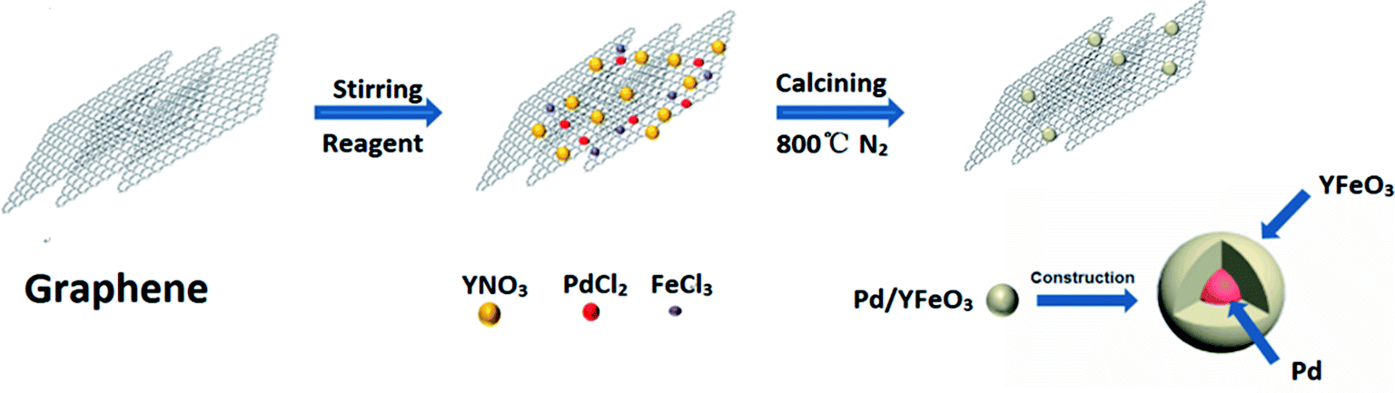 | ||
| Scheme 1 Schematic formation of the Pd/YFeO3/GC composite. | ||
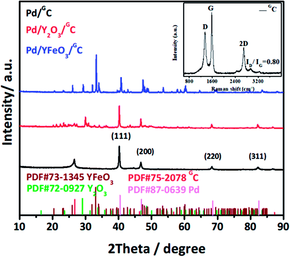 | ||
| Fig. 1 XRD patterns of Pd/GC, Pd/Y2O3/GC and Pd/YFeO3/GC. | ||
The SEM images of Pd/GC, Pd/Y2O3/GC and Pd/YFeO3/GC composite are shown in Fig. 2a–c. In Fig. 2c, the graphene was uniformly decorated on the Pd/YFeO3 nanoparticles. The TEM images of Pd/GC, Pd/Y2O3/GC and Pd/YFeO3/GC composite are shown in Fig. 2d–f. Fig. 2f shows a TEM image of the Pd/YFeO3/GC composite. Metal particles are uniformly deposited on the graphene. The average particle size is estimated to be 14.2 nm for the Pd/YFeO3/GC based on the measurement of 100 particles in random regions. Fig. 2g shows that the lattice spacing is 0.270 nm, which corresponds to the (121) plane of YFeO3; the lattice spacing of 0.244 nm corresponds to the (111) plane of Pd, which is consistent with the XRD results. Fig. 2g indicates that Pd is wrapped by YFeO3 alloy. This alloy layer is very thin, which can improve the performance and stability of Pd in 0.5 M H2SO4. Fig. 2h shows that the TEM image of Pd/YFeO3/GC after 8000 cycles in 0.5 M H2SO4 aqueous solution at a scan rate of 10 mV s−1. From the TEM image, it was found that the metal particles in Pd/YFeO3/GC were uniformly dispersed and unchanged on the graphene. This means the Pd/YFeO3/GC is very stable in 0.5 M H2SO4 aqueous solution. Fig. 3a–d further confirms the sample elements and distribution. The Pd, Fe, and Y mapping of Pd/YFeO3/GC clearly shows that the elements are distributed evenly on the graphene; Pd is encapsulated by the YFeO3 alloy. The distribution of the elements is clearly shown in the mapping. Pd/YFeO3/GC samples were obtained via nitrogen adsorption/desorption measurements (Fig. 4a). The hysteresis curves between 0–1.0 p/p0 are obviously type IV indicating that there is a large number of ordered micropores and mesopores in the catalyst material due to the layered structure.25 The BET surface area of Pd/YFeO3/GC approaches 439 m2 g−1, which illustrates the benefits of using graphene—it can give the sample a larger specific surface area to increase the sample's conductivity and electron mobility. The BJH analysis showed that the Pd/YFeO3/GC has a pore volume of 0.3124 cm3 g−1 and with a non-homogenous pore size distribution (Fig. 4b). The non-uniform pore size distribution may be due to particle aggregation in the catalyst. The BJH adsorption average pore width (4V/A) was 6.3856 nm, and the BJH adsorption average pore width (4V/A) was 6.3204 nm. These data suggested that the catalyst is mainly mesoporous. These qualities have been widely recognized as beneficial for an ample electrode/electrolyte interface for ion or charge accumulation performance during the HER and OER processes.26
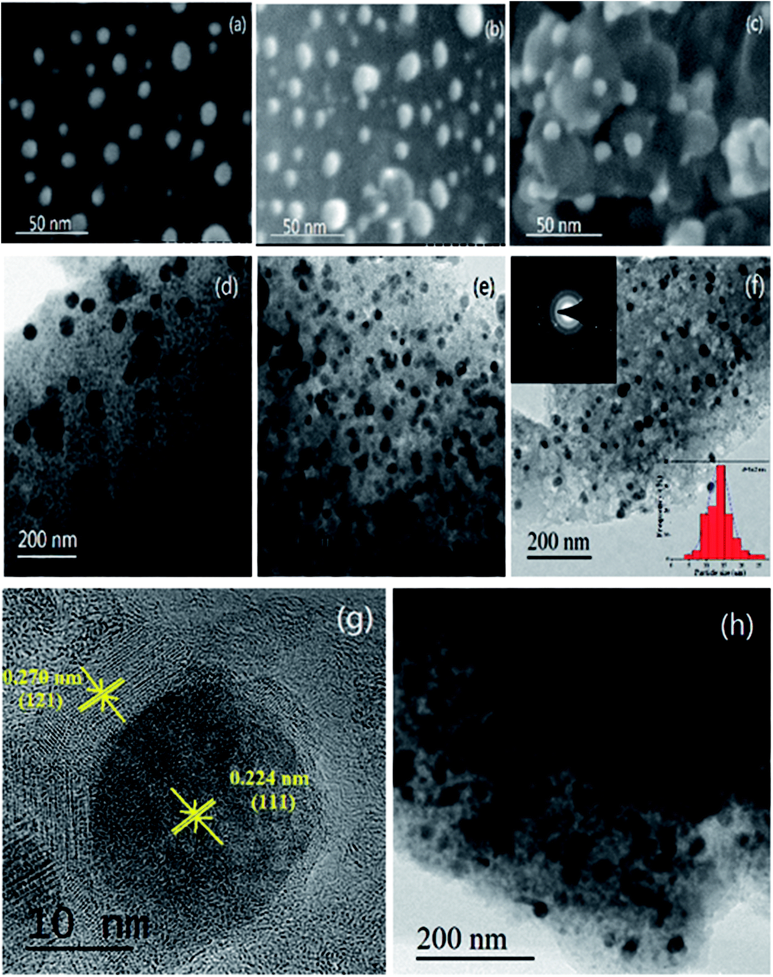 | ||
| Fig. 2 The SEM images of Pd/GC, Pd/Y2O3/GC and Pd/YFeO3/GC are shown in (a), (b) and (c) and the TEM images of Pd/GC, Pd/Y2O3/GC and Pd/YFeO3/GC are shown in (d), (e) and (f). (g) HRTEM image of a part of the Pd/YFeO3/GC in (f). (h) The TEM image of Pd/YFeO3/GC after 8000 cycles in 0.5 M H2SO4 aqueous solution at a scan rate of 10 mV s−1. | ||
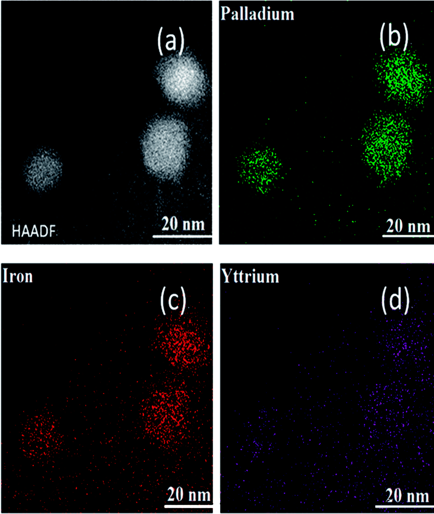 | ||
| Fig. 3 (a–d) STEM-HAADF image and element mapping images of the Pd/YFeO3/GC composite. | ||
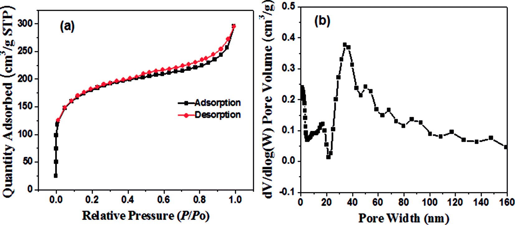 | ||
| Fig. 4 (a) Nitrogen adsorption/desorption isotherm of Pd/YFeO3/GC and (b) DFT pore size distribution of Pd/YFeO3/GC. | ||
Fig. 5a shows the binding configurations of different elements in Pd/YFeO3/GC via XPS. The presence of Pd, Fe, Y, C, and O was obvious in the survey spectrum of the Pd/YFeO3/GC nanocomposite system. Fig. 5b shows the XPS spectra and indicates the presence of surface Pd in the form of two peaks at 336.3 eV and 341.5 eV. These were resolved for Pd (2p5/2) and Pd (2p3/2)27,28 confirming elemental Pd. The XPS spectra fitting processing of Fe is shown in Fig. 5c. The peak at 727 eV can be matched with Fe3+, and the peak at 712 eV matches Fe2+. In Fig. 5d, the Y 3d was observed at 157.9 and 159.8 eV.29,30 The two peaks of C (1s) at 284.7 and 285.3 eV show two types of carbon. The peak at 284.7 eV is involved in C–C bonds, and the peak at 285.3 eV is involved in C–N bonds.31,32
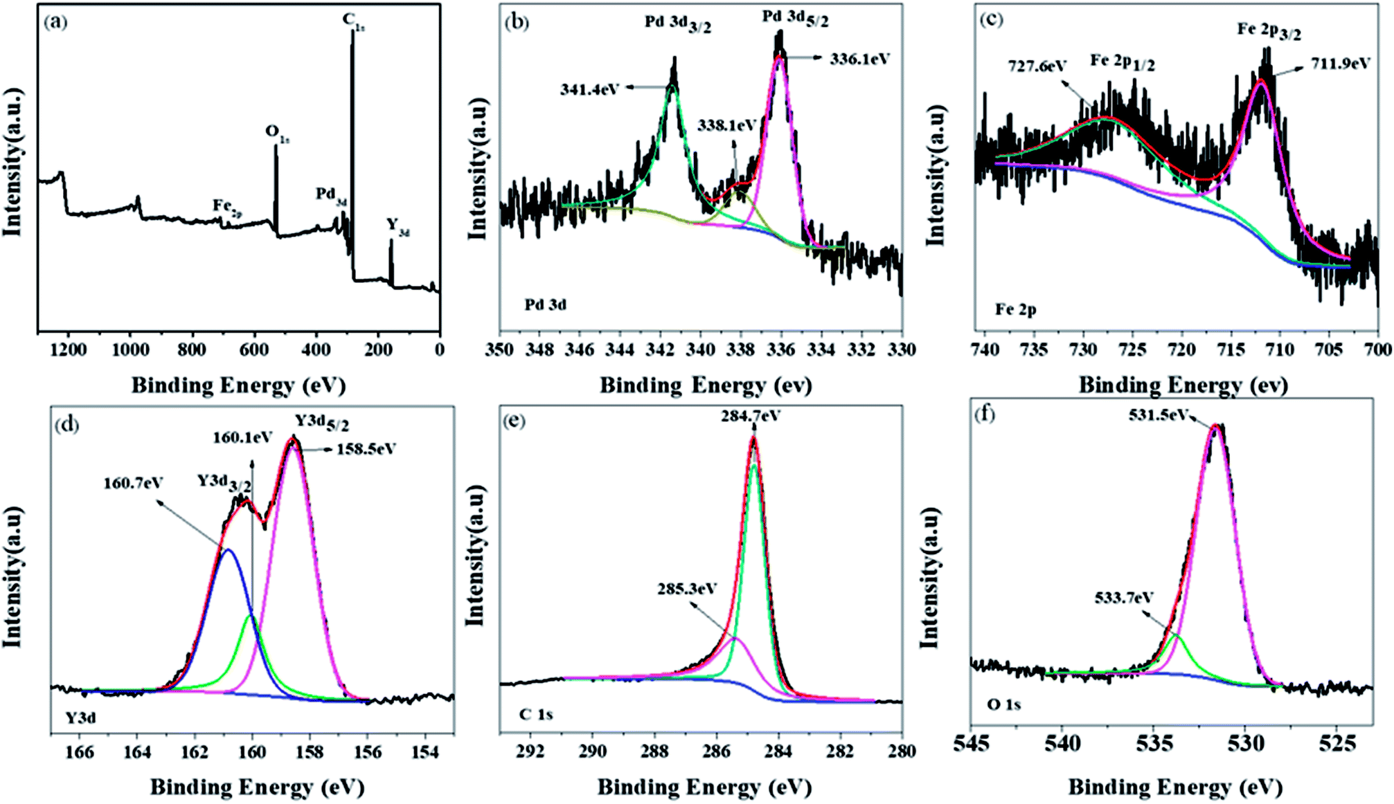 | ||
| Fig. 5 (a) Pd/YFeO3/GC XPS spectrum, (b), (c), (d), (e) and (f) are Pd, Fe, Y, C and O respectively. | ||
The HER activity of Pd/YFeO3/GC was investigated via electrochemical measurements in 0.5 M H2SO4. At a current density of 10 mA cm−2, the Pd/YFeO3/GC showed excellent low overpotential of 15 mV—this is the same as the overpotential of the Pt/C and is lower than Pd/C (43 mV), Pd/GC (37 mV), and Pd/Y2O3/GC (26 mV) (Fig. 6a). In addition, Pd/YFeO3/GC only needs potentials of about −0.03 V, −0.042 V, and −0.076 V to reach current densities of 20, 30 and 60 mA cm−2, respectively. The HER activity of Pd/YFeO3/GC is the best in all the as-prepared catalysts because of the reduction of Pd–H binding energy, which is due to the Pd lattice parameter compressed with the addition of YFeO3 and the improvement of the electrical conductivity of palladium by graphene.33. The Tafel plots of Pd/C, Pd/GC, Pd/Y2O3/GC and Pd/YFeO3/GC are shown in Fig. 6b. The Tafel slope of Pd/YFeO3/GC is 37 mV per decade, which is lower than the other samples and is very close to the Tafel slope of Pt/C (33 mV per decade). To investigate the stability of Pd/YFeO3/GC catalysts, we first assessed the circulation stability of Pd/YFeO3/GC following the accelerated durability test protocol by cycling the potential between 0.1 V and −0.3 V at 100 mV s−1 for HER as represented in Fig. 6c. The LSV curves of Pd/YFeO3/GC had no change after 8000 cyclic voltammetry (CV) cycles versus baseline. This highlights the cycling stability of the sample and proves that the catalyst is very stable for HER. Then we conducted a chronoamperometry test for HER with the current density fixed at 20 mA cm−2 with 1600 rpm in N2-saturated 0.5 M H2SO4 solutions 60 hours shown in Fig. 6d. The test revealed that Pd/YFeO3/GC catalysts' HER potentials remained very stable with increases of only 30 mV after measured continuously 60 h.
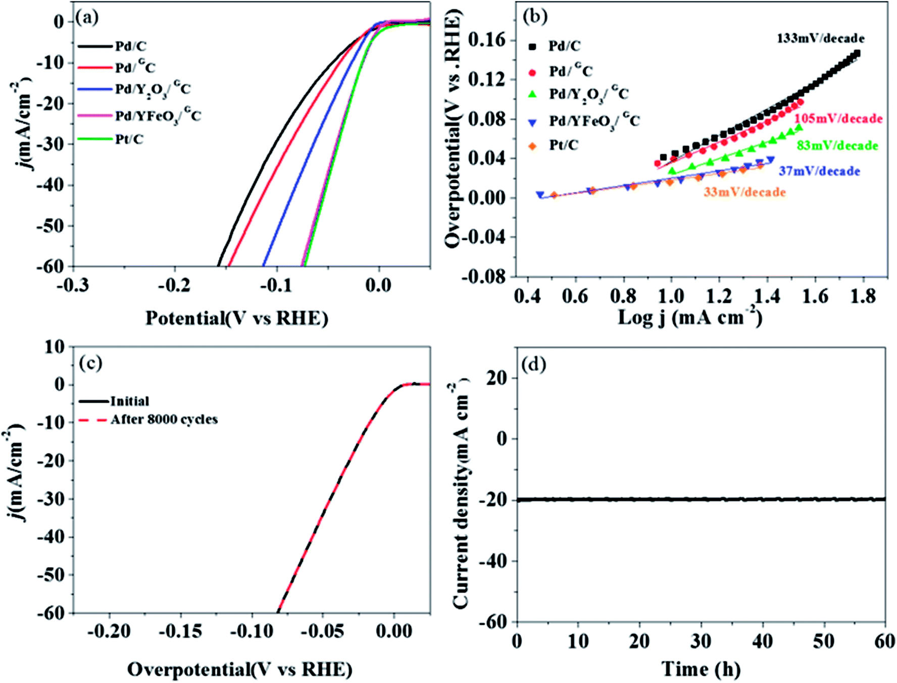 | ||
| Fig. 6 (a) LSV curves of graphene or carbon powder modified with noble metals. (b) HER Tafel plots of Pd/C, Pd/GC, Pd/Y2O3/GC, Pd/YFeO3/GC and Pt/C. (c) The stability polarization curve of Pd/YFeO3/GC before and after 8000 cycles in 0.5 M H2SO4 aqueous solution at a scan rate of 10 mV s−1 and (d) Pd/YFeO3/GC constant voltage stability diagram. All data were IR corrected. | ||
4 Conclusions
In conclusion, Pd/C, Pd/GC, Pd/Y2O3/GC, and Pd/YFeO3/GC catalysts were successfully synthesized. The HER activity of the Pd/YFeO3/GC composite is better than the other catalysts in 0.5 M H2SO4 solution. The activity of the Pd/YFeO3/GC composite for the HER is the same as commercial Pt/C due to the porous multilayer structure of graphene and the HER activity of YFeO3. The Pd/YFeO3/GC composite exhibits a low overpotential, small Tafel slope, and robust HER durability. The Pd/YFeO3/GC composite is more easily prepared than other non-noble metal catalysts, and it is the most promising energy storage material.Conflicts of interest
There are no conflicts to declare.Acknowledgements
This work was supported by the National Basic Research Program of China (2015CB932304), the Major International (Regional) Joint Research Project (51210002), the Natural Science Foundation of Guangdong Province (2015A030312007), the Guangxi Science and Technology Project (AB16380030), and the Danish Initiative Towards Non-precious Metal Polymer Fuel Cells (4106-000012B).References
- S. Chu and A. Majumdar, Nature, 2012, 488, 294–303 CrossRef CAS.
- J. O. M. Bockris, Int. J. Hydrogen Energy, 2003, 28, 131–133 CrossRef.
- J. A. Turner, Science, 2004, 305, 972–974 CrossRef CAS.
- J. Kibsgaard and T. F. Jaramillo, Angew. Chem., Int. Ed., 2014, 53, 14433 CrossRef CAS PubMed.
- T. Ding, Z. Wang, L. Zhang, C. Wang, Y. Sun and Q. Yang, J. Mater. Chem. A, 2016, 4, 15309–15315 RSC.
- M. Wu, P. K. Shen, Z. Wei, S. Song and M. Nie, J. Power Sources, 2007, 166, 310–316 CrossRef CAS.
- J. Lu, L. Zhang, S. Jing, L. Luo and S. Yin, Int. J. Hydrogen Energy, 2017, 42, 5993–5999 CrossRef CAS.
- H. Lv, X. Chen, D. Xu, Y. Hu, H. Zheng, S. L. Suib and B. Liu, Appl. Catal., B, 2018, 238, 525–532 CrossRef CAS.
- H. Du, Q. Liu, N. Cheng, A. M. Asiri, X. Sun and C. M. Li, J. Mater. Chem. A, 2014, 2, 14812–14816 RSC.
- W. Zhou, D. Hou, Y. Sang, S. Yao, J. Zhou, G. Li, L. Li, H. Liu and S. Chen, J. Mater. Chem. A, 2014, 2, 11358–11364 RSC.
- J. Jiang, C. Wang, J. Zhang, W. Wang, X. Zhou, B. Pan, K. Tang, J. Zuo and Q. Yang, J. Mater. Chem. A, 2015, 3, 499–503 RSC.
- Y. Jin and P. K. Shen, J. Mater. Chem. A, 2015, 3, 20080–20085 RSC.
- L. Zhang, J. Mu, Z. Wang, G. Li, Y. Zhang and Y. He, J. Alloys Compd., 2016, 671, 60–65 CrossRef CAS.
- J. Yin, Q. Fan, Y. Li, F. Cheng, P. Zhou, P. Xi and S. Sun, J. Am. Chem. Soc., 2016, 138, 14546–14549 CrossRef CAS.
- J. Jin, Y. Zhu, Y. Liu, Y. Li, W. Peng, G. Zhang, F. Zhang and X. Fan, Int. J. Hydrogen Energy, 2017, 42, 3947–3954 CrossRef CAS.
- A. Bazylak, D. Sinton and N. Djilali, J. Power Sources, 2005, 143, 57–66 CrossRef CAS.
- F. Mathieu-Potvin and L. Gosselin, Int. J. Hydrogen Energy, 2014, 39, 7382–7401 CrossRef CAS.
- Y. Jin, H. Wang, J. Li, X. Yue, Y. Han, P. K. Shen and Y. Cui, Adv. Mater., 2016, 28, 3785–3790 CrossRef CAS.
- B. Hinnemann, P. G. Moses, J. Bonde, K. P. Jorgensen, J. H. Nielsen, S. Horch, I. Chorkendorff and J. K. Norskov, J. Am. Chem. Soc., 2005, 127, 5308–5309 CrossRef CAS.
- L. Chai, W. Yuan, X. Cui, H. Jiang, J. Tang and X. Guo, RSC Adv., 2018, 8, 26871–26879 RSC.
- A. C. Ferrari, J. C. Meyer, V. Scardaci, C. Casiraghi, M. Lazzeri, F. Mauri, S. Piscanec, D. Jiang, K. S. Novoselov and S. Roth, Phys. Rev. Lett., 2006, 97, 187401 CrossRef CAS.
- Z. Jin, J. Yao, C. Kittrell and J. M. Tour, ACS Nano, 2011, 5, 4112 CrossRef CAS.
- A. C. Ferrari, Solid State Commun., 2007, 143, 47–57 CrossRef CAS.
- A. C. Ferrari and D. M. Basko, Nat. Nanotechnol., 2013, 8, 235–246 CrossRef CAS.
- Z.-Y. Wu, X.-X. Xu, B.-C. Hu, H.-W. Liang, Y. Lin, L.-F. Chen and S.-H. Yu, Angew. Chem., Int. Ed., 2015, 54, 8179–8183 CrossRef CAS.
- J. Hou, C. Cao, F. Idrees and X. Ma, ACS Nano, 2015, 9, 2556–2564 CrossRef CAS PubMed.
- T. Bhowmik, M. K. Kundu and S. Barman, ACS Catal., 2016, 6, 1929–1941 CrossRef CAS.
- K. Qi, S. Yu, Q. Wang, W. Zhang, J. Fan, W. Zheng and X. Cui, J. Mater. Chem. A, 2016, 4, 4025–4031 RSC.
- M. H. Seo, S. M. Choi, J. K. Seo, S. H. Noh, W. B. Kim and B. Han, Appl. Catal., B, 2013, 129, 163–171 CrossRef CAS.
- X. Liu, E. H. Yu and K. Scott, Appl. Catal., B, 2015, 162, 593–601 CrossRef CAS.
- L. Tao, Q. Wang, S. Dou, Z. Ma, J. Huo, S. Wang and L. Dai, Chem. Commun., 2016, 52, 2764–2767 RSC.
- T. Cheng and Z. Qiang, Adv. Mater., 2017, 29, 1604103 CrossRef PubMed.
- N. Danilovic, R. Subbaraman, D. Strmcnik, V. R. Stamenkovic and N. M. Markovic, J. Serb. Chem. Soc., 2013, 78, 2007–2015 CrossRef CAS.
| This journal is © The Royal Society of Chemistry 2018 |