 Open Access Article
Synergistic effect of functionalized graphene oxide and carbon nanotube hybrids on mechanical properties of epoxy composites†
Zehao Qia,
Yefa Tan *a,
Zhongwei Zhangb,
Li Gaoa,
Cuiping Zhanga and
Jin Tiana
aCollege of Field Engineering, PLA Army Engineering University, Nanjing 210007, China. E-mail: tanyefa7657@163.com
bState Key Laboratory for Disaster Prevention & Mitigation of Explosion & Impact, PLA Army Engineering University, Nanjing 210007, China
First published on 16th November 2018
Abstract
Epoxy resin was grafted to graphene oxide (GO) via esterification reaction and 3D structure hybrids were prepared by combining 1D carbon nanotube (CNT) and 2D functionalized GO through π-stacking interaction. Epoxy composites filled with 3D structure hybrids were fabricated. The results show that functionalized GO effectively improves the dispersibility of CNTs in epoxy matrix due to good compatibility. Excellent mechanical properties were achieved by epoxy composites filled with 3D structure hybrids. The fracture surface analysis indicated improved interfacial interaction between 3D structure hybrids and epoxy matrix, which may due to the covalent bonding formed between the epoxy molecular chain grafted on EGO and the hardener agent during the curing process. In the 3D structure filler network, the mechanisms of crack deflection/bifurcation induced by functionalized GO make the crack path tortuous, which causes the cracks to encounter more CNTs and then promote the mechanisms of CNT fracture and crack bridging, resulting in more energy dissipation. This is the key mechanism for its excellent reinforcing and toughening effects.
1. Introduction
Carbon nanotubes (CNTs) with one dimensional (1D) structure, are one of the most promising candidates for use as reinforcing fillers in polymer composites, due to their extremely high mechanical strength, excellent heat transfer capability and electrical conductivity.1–3 Recently, many studies have shown that CNTs can effectively improve the mechanical properties of polymer composites.4–6 However, due to the strong van der Waals force interaction among CNTs, they usually entangle with each other and are difficult to be uniformly dispersed in polymer matrix. This affects the reinforcing effect of CNTs and further limits their application in polymer composites. To solve this problem, researchers have made a lot of effort on researching dispersing CNTs in polymer matrix via CNT functionalization through either covalent or noncovalent methods.7–12 For the method of covalent functionalization, the CNT structure may be impaired and the mechanical properties of the composites may be influenced.13–15 Therefore, the noncovalent functionalization of CNTs is more attractive because it is based on π-stacking, CH–π, hydrogen bonding or electrostatic interaction to adsorb surfactants or polymer onto its surface without impairing the structure of CNTs.16–18Recently, graphene oxide (GO), a two-dimensional (2D) nanomaterial with sp2 hybridized single-atom thick sheets, has attracted tremendous interest of the scientists because of its extraordinary mechanical and thermal properties.19–21 The surface of GO bears abundant oxygen-containing groups, such as hydroxyl and epoxy groups on the basal planes of GO and carboxyl groups at the edges of GO. Thus, GO can be used to functionalize CNT and construct 3D GO/CNT hybrids through π-stacking interaction formed between the π-conjugated multiple aromatic regions of GO sheets and the sidewalls of CNTs. This 3D structure hybrids may overcome the dispersion problem faced by the individual fillers.22–24 Tian et al.22 reported that GO effectively improved the dispersibility of GO in aqueous solution. Unlike surfactant or polymer dispersants, GO can act as not only dispersant but also reinforcing filler due to its extraordinary mechanical performance. In addition, oxygen-containing groups make GO available for further functionalization with proper polymer, which can improve its compatibility and interfacial interaction in corresponding polymer matrix.25–28 Thus, it is expected that GO functionalized with proper polymer can be used to disperse CNTs in corresponding polymer matrix because of its well compatibility and the 3D structure hybrids formed by functionalized GO and CNT can develop strong interfacial interaction with polymer matrix. However, by now, studies have only focused on the synergistic approach by using unmodified GO (or graphene) and CNT,29,30 there is no report about the synergistic approach by using polymer functionalized GO and CNT for epoxy composites.
In this study, GO was functionalized with epoxy resin via esterification reaction and the epoxy composites filled with 3D structure hybrids by combining 1D CNT and 2D functionalized GO were fabricated. The dispersion of 3D structure hybrids in epoxy matrix was studied. The effect of GO functionalization on the co-dispersing effect of GO and CNT hybrids was analyzed. The mechanical properties of 3D structure hybrids reinforced epoxy composites were tested and the synergistic effect on the improvement of mechanical properties of epoxy composites was demonstrated. Moreover, the failure mechanisms of 3D structure hybrids were revealed through fracture morphology analysis, which aims to provide theoretical basis for the practical application of GO and CNT in polymer matrix composites.
2. Experimental
2.1. Materials
MWCNTs with a diameter of 20–30 nm and a purity of more than 95% were provided by Nanjing XFNANO Materials Tech Co., Ltd, China. Graphite powder (4000 mesh) was supplied by Shanghai Aladdin Reagent Co., Ltd, China. The epoxy resin used in this study was a bisphenol A epoxy resin (WSR618) with an epoxy equivalent of 185–192 g eq−1 from Bluestar Wuxi Petrochemical Co., Ltd, China. The curing agents were QS-1622 supplied by Beijing Qingda-QS Materials Co., Ltd, China, which was modified aromatic amine. The mixing ratio of QS-1622 and WSR618 used in this study was 1![[thin space (1/6-em)]](https://www.rsc.org/images/entities/char_2009.gif) :
:![[thin space (1/6-em)]](https://www.rsc.org/images/entities/char_2009.gif) 2.
2.
Sodium nitrate, potassium permanganate, sulfuric acid, hydrogen peroxide, hydrochloric acid, triphenyl phosphine (TPP), tetrahydrofuran (THF), N,N-dimethylformamide ethanol (DMF) and ethanol were supplied by Shanghai Aladdin Reagent Co., Ltd, China, and used without further purification.
2.2. Preparation of functionalized GO
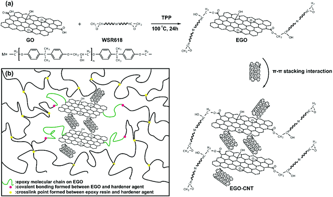
GO was prepared by modified Hummers method.31,32 GO was dried under vacuum for 24 h at 80 °C, and then was dispersed in DMF by sonification. WSR618 was also dissolved in DMF by mechanical stirring. After that, the above two DMF dispersions were mixed and stirred for 1 h at room temperature. Then TPP (0.5 wt% to WSR 618) was added to catalyze the reaction.25 The reaction was allowed to proceed for 24 h at 100 °C (shown in Scheme 1a). The reaction product was diluted with ethanol and subsequently filtered with a polycarbonate (PC) membrane (10 μm pore size). Then the obtained solid was washed with excess ethanol and the procedures of filtering and washing were repeated for 5 times. The obtained solid was dried under vacuum until the weight was constant and the finally obtained product was epoxy functionalized GO (EGO).2.3. Preparation of EGO and CNT hybrids
EGO and CNT hybrids were prepared via π-stacking interaction. Firstly, equal mass of EGO and CNT were added in THF and sonicate for 2 h. Then the dispersed solution was filtered with a PC membrane and dried under vacuum. The obtained solids were EGO and CNT hybrids (EGO-CNT). The 3D structure of EGO-CNT formed by π–π stacking interaction among EGO and CNTs was shown in Scheme 1a. In addition, GO and CNT hybrids (GO-CNT) were also prepared for comparison.2.4. Preparation of epoxy composites
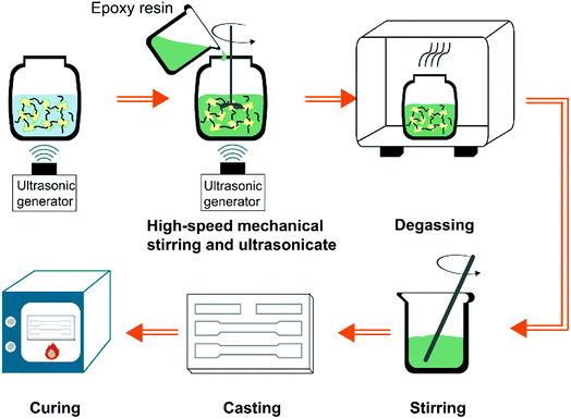
To investigate the dispersion of EGO-CNT and their synergistic effect, the filler content was fixed at 1 wt% for comparison. The fabrication schematic of EGO-CNT/EP is shown in Fig. 1. Epoxy composites filled with EGO-CNT were prepared according to the following steps: EGO-CNT was firstly dispersed in THF by sonicating for 2 h. After sonication, the dispersed solution was mixed with epoxy resin using sonification and high-speed mechanical stirring. The blend was sonicated at 60 °C for 2 hours while it was stirred at a high-speed of 2000 rpm. Finally, the dispersed blend was degassed for 24 hours in vacuum and subsequently mixed with the curing agent. After stirring for 5 min, the blend was casted into the PTFE mold for curing. The obtained products were EGO-CNT reinforced epoxy composites (EGO-CNT/EP). The crosslinking network of EGO-CNT/EP was shown in Scheme 1b. Owing to the epoxy group, EGO-CNT forms covalent bonding with the epoxy matrix and link into the crosslinked network, contributing to the improvement of mechanical performance. For comparison, pure epoxy resins (EP), CNT reinforced epoxy composites (CNT/EP), GO reinforced epoxy composites (GO/EP), EGO reinforced epoxy composites (EGO/EP) and GO-CNT reinforced epoxy composites (GO-CNT/EP) were also prepared.2.5. Characterization
The FT-IR spectra were obtained on a IS-10 (Nicolet) spectrometer. The spectral range was 500–4000 cm−1. Dried powders of carbon nanofillers (GO, CNT, EGO and EGO-CNT) were used for characterization. The prepared GO and EGO were further characterized by X-ray photoelectron (XPS) spectra using an ESCALAB 250Xi (ThermoFisher) spectrometer. The excitation source was an Al Kα line at 1486.6 eV. The powders of samples (GO, CNT, EGO, GO-CNT and EGO-CNT) were analyzed by X-ray diffraction (XRD) using a D8 Advance (Bruker) diffractometer with Cu Kα radiation (λ = 0.154178 nm). The tube voltage was 40 kV and the current was 200 mA. Scans were taken over the 2θ range of 5° to 45° with the scanning rate of 4° min−1. The Raman spectra were measured on Aramis (Horiba Jobin Yvon) with 532 nm red line of a He–Ne laser. A 50× objective lens was used to focus the laser beam on sample surface (laser spot: 200 μm).For observing morphologies of carbon nanofillers, the sample was firstly dispersed in THF by sonification. A few drops of the supernatant solutions were then deposited onto copper grids. After the solvent evaporated to dryness, transmission electron microscopy (TEM, JEM-2100 JEOL) was performed. In order to observe the dispersion of carbon nanofillers in the epoxy matrix, the ultra-thin sections of epoxy and nanocomposites were obtained using a EM FC6 cryosectioning apparatus (Leica, Germany). The ultra-thin sections were then placed on the copper grids and observed by TEM. The fracture surface of the specimens coated with a gold layer in advance was observed by scanning electron microscope (SEM, S4800 Hitachi).
Tensile properties were obtained by American SANS CMT5105 electronic universal testing machine using dumbbell shaped specimens. The measurements were carried on at the speed of 5 mm min−1 according to the ASTM D638-2010 standard. To ensure the accuracy of the data, at least five samples were tested for each category. The fracture toughness of the composites was determined using the single edge notched bend (SENB) specimens in accordance with ASTM D 5045-99. The size of the rectangular specimen was 50 mm × 10 mm × 5 mm. A notch was machined and then a pre-crack was introduced by tapping a fresh razor blade into each specimen. The tests were performed at room temperature with a loading rate of 1 mm min−1 and at least five samples were tested for each category. The fracture toughness (KIC) and the critical energy release rate (GIC) can be calculated by the following equation:33
 | (1) |
 | (2) |
3. Results and discussion
3.1. Characterization of prepared carbon nanofillers
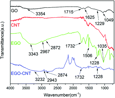
FT-IR spectra were analyzed to identify the chemical composition and variation of GO, CNT, EGO and EGO-CNT. Fig. 2 shows the FT-IR spectra of GO, CNT, EGO and EGO-CNT. In the spectrum of GO, the peaks at 3354 cm−1, 1715 cm−1, 1625 cm−1, 1229 cm−1 and 1049 cm−1 are attributed to O–H stretching vibrations, C![[double bond, length as m-dash]](https://www.rsc.org/images/entities/char_e001.gif) O stretching vibration, C
O stretching vibration, C![[double bond, length as m-dash]](https://www.rsc.org/images/entities/char_e001.gif) C stretching vibration and C–O stretching vibrations, respectively, which is consistent with the previous reports.34,35 After functionalization, the spectrum of EGO shows new peaks at 2967 cm−1, 2872 cm−1 and 1506 cm−1, corresponding to the symmetric and asymmetric stretching vibration of methylene and stretching vibration of benzene ring in the epoxy resin. In addition, it is observed that the C
C stretching vibration and C–O stretching vibrations, respectively, which is consistent with the previous reports.34,35 After functionalization, the spectrum of EGO shows new peaks at 2967 cm−1, 2872 cm−1 and 1506 cm−1, corresponding to the symmetric and asymmetric stretching vibration of methylene and stretching vibration of benzene ring in the epoxy resin. In addition, it is observed that the C![[double bond, length as m-dash]](https://www.rsc.org/images/entities/char_e001.gif) O stretching vibration peak shifted from 1715 cm−1 (the C
O stretching vibration peak shifted from 1715 cm−1 (the C![[double bond, length as m-dash]](https://www.rsc.org/images/entities/char_e001.gif) O stretching vibration peak of carboxylic acid on GO) to 1732 cm−1 (the C
O stretching vibration peak of carboxylic acid on GO) to 1732 cm−1 (the C![[double bond, length as m-dash]](https://www.rsc.org/images/entities/char_e001.gif) O stretching vibration peak of ester carbonyl on EGO), which proves the esterification reaction between epoxy groups in the epoxy resin and carboxylic acid groups on GO. These variations demonstrate that epoxy resins have grafted on the GO surface after functionalization. The spectrum of CNT does not show any peaks corresponding to functional groups. However, the characteristic peaks of EGO are observed from the spectrum of EGO-CNT, indicating the composition of CNT and EGO.
O stretching vibration peak of ester carbonyl on EGO), which proves the esterification reaction between epoxy groups in the epoxy resin and carboxylic acid groups on GO. These variations demonstrate that epoxy resins have grafted on the GO surface after functionalization. The spectrum of CNT does not show any peaks corresponding to functional groups. However, the characteristic peaks of EGO are observed from the spectrum of EGO-CNT, indicating the composition of CNT and EGO.
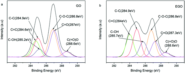
To further determine the chemical composition and variation of GO and EGO, XPS was performed and the results are shown in Fig. 3. The C 1s core level spectra of GO (Fig. 3a) present six types of carbon: sp2 C![[double bond, length as m-dash]](https://www.rsc.org/images/entities/char_e001.gif) C (284.6 eV), sp3 C–C in aromatic rings (284.9 eV), C–OH (285.2 eV), C–O–C (286.8 eV), C
C (284.6 eV), sp3 C–C in aromatic rings (284.9 eV), C–OH (285.2 eV), C–O–C (286.8 eV), C![[double bond, length as m-dash]](https://www.rsc.org/images/entities/char_e001.gif) O (287 eV) and O–C
O (287 eV) and O–C![[double bond, length as m-dash]](https://www.rsc.org/images/entities/char_e001.gif) O (288.6 eV), in good agreement with the data reported in the literature.36,37 After functionalization, the intensity of C–O–C (286.8 eV), C
O (288.6 eV), in good agreement with the data reported in the literature.36,37 After functionalization, the intensity of C–O–C (286.8 eV), C![[double bond, length as m-dash]](https://www.rsc.org/images/entities/char_e001.gif) O (287.3 eV) and O–C
O (287.3 eV) and O–C![[double bond, length as m-dash]](https://www.rsc.org/images/entities/char_e001.gif) O (288.6 eV) are significantly weakened while the intensity of C
O (288.6 eV) are significantly weakened while the intensity of C![[double bond, length as m-dash]](https://www.rsc.org/images/entities/char_e001.gif) C (284 eV), C–C (284.9 eV) and C–OH (285.7 eV) are increased (Fig. 3b). In particular, the increasement of sp3 C–C (284.9 eV) intensity was obviously high, which can be attributed to the alkane group in epoxy resin.38 Meanwhile, GO contains 65.6 atom% of carbon and 34.4 atom% of oxygen. After functionalization, the carbon content increased up to 71.4 atom%, while oxygen content decreased to 28.6 atom% (C/O atomic ratio of 1.9 for GO and 2.5 for EGO. See Fig. S1 in ESI†). This obvious change can be attributed to the relatively high density of C
C (284 eV), C–C (284.9 eV) and C–OH (285.7 eV) are increased (Fig. 3b). In particular, the increasement of sp3 C–C (284.9 eV) intensity was obviously high, which can be attributed to the alkane group in epoxy resin.38 Meanwhile, GO contains 65.6 atom% of carbon and 34.4 atom% of oxygen. After functionalization, the carbon content increased up to 71.4 atom%, while oxygen content decreased to 28.6 atom% (C/O atomic ratio of 1.9 for GO and 2.5 for EGO. See Fig. S1 in ESI†). This obvious change can be attributed to the relatively high density of C![[double bond, length as m-dash]](https://www.rsc.org/images/entities/char_e001.gif) C, C–C and C–OH in the epoxy resin, indicating successfully grafting of epoxy resins on GO.
C, C–C and C–OH in the epoxy resin, indicating successfully grafting of epoxy resins on GO.
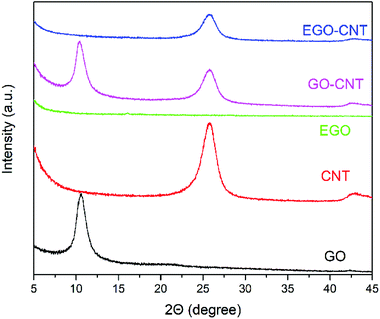
The structures of GO, CNT, EGO, GO-CNT and EGO-CNT were analyzed by XRD and spectra are shown in Fig. 4. The XRD spectrum of GO shows a sharp diffraction peak (001) at 2θ = 10.7°, corresponding to an interlayer spacing of 0.83 nm, which is due to the generation of oxygen functionalities in the basal plane of the graphite.30 After functionalization, the sharp diffraction peak disappears and no other diffraction peaks are observed in the XRD spectrum of EGO, indicating that the epoxy resins grafted on the surface of EGO change the stacking structure of EGO and exfoliate GO sheets. The diffraction peak (002) of CNT observed at 2θ = 25.8° is ascribed to the graphitic carbon of CNT.39 For GO-CNT, both the diffraction peak (001) at 2θ = 10.7° and diffraction peak (002) at 2θ = 25.8° are observed, indicate the integration of CNTs with GO sheets.40 Compared with GO-CNT, there is no apparent diffraction peak (001) of GO for EGO-CNT. This may be attributed to the effective exfoliation of GO sheets in EGO-CNT.
Raman spectroscopy is a powerful tool in investigating the surface defects and the quality of the crystalline structure of carbon nanofillers.41 The D band at 1340 cm−1 is attributed to the defects in the disorder-induced modes (sp3 hybridized carbons). The G band at 1570 cm−1 is usually attributed to the in-plane bond-stretching motion of the pairs of C sp2 atoms. Thus, the intensity ratio of the D band to the G band (ID/IG) is a measure of sp3 surface defects within the sp2 network structure of graphitic materials.42 Fig. S2† shows the Raman spectra of GO, CNT, EGO, GO-CNT and EGO-CNT. It was noted that the intensity ratio of the D to G band (ID/IG) of GO (1.02) slightly increases to 1.07 after functionalization, indicating that the functionalization method used in this study produced few defects on the sp2 network structure of GO. In addition, the ID/IG ratios of GO-CNT (0.94) and EGO-CNT (0.97) are lower than that of GO (1.02) or EGO (1.07) and higher than that of CNT (0.89), suggesting that it consists of GO (or EGO) and CNT.
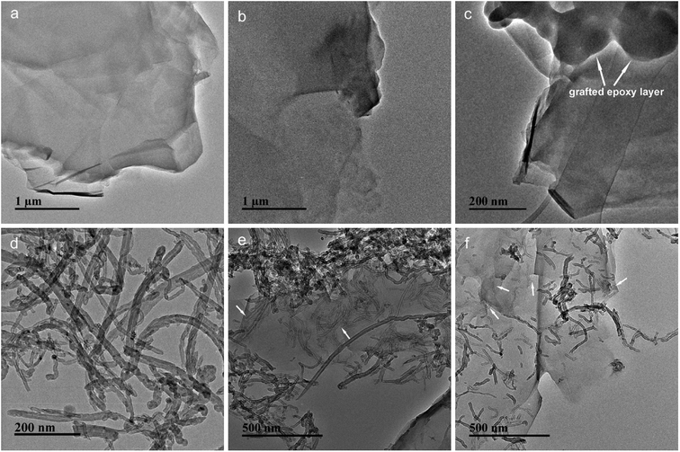
The morphologies of GO, EGO, CNT, GO-CNT and EGO-CNT were investigated by TEM imaging as displayed in Fig. 5. As shown in Fig. 5a, GO has some wrinkled, folded structures and shows a soft, smooth surface. After functionalization, the surface of EGO become rough (Fig. 5b), which may be attributed to the epoxy molecular chain. It can be seen more clearly from the HRTEM image of EGO (Fig. 5c) that the surface of GO is covered by numerous irregular material (indicated by the white arrows), which is assumed to be epoxy molecular chain. Meanwhile, it can be seen from Fig. 5d that most CNTs tend to entangle with each other. For GO-CNT, most CNTs attach on the edge of GO sheets and few CNTs penetrate into the interlayer space of GO sheets (indicated by the white arrows) suggesting 3D nanostructure of GO-CNT but entangled CNTs still can be found (Fig. 5e). This similar behavior of CNTs (penetrate into the graphene layers) also have been found by previous reports.29,43,44 However, for EGO-CNT, CNTs are disentangled and redistributed on the surface of EGO (Fig. 5f), resulting in many individual CNTs. Meanwhile, many CNTs penetrate into the interlayer space of EGO sheets (indicated by the white arrows in Fig. 5f) via π-stacking interaction, which act as a bridge between adjacent EGO sheets, thus forming 3D structure hybrids.45
3.2. Dispersion and morphology of carbon nanofillers in epoxy matrix
TEM images of epoxy composites prepared by the ultrathin section were performed to investigate the dispersion and morphology of GO, EGO, CNT, GO-CNT and EGO-CNT in epoxy matrix. As shown in Fig. 6a, some black region with different sizes can be clearly observed, suggesting that the GO are relatively agglomerated in epoxy matrix. However, after functionalization, EGO exhibit highly exfoliated and uniformly dispersed in epoxy matrix without any scale aggregations (Fig. 6b), which can be attributed to well compatibility of EGO. For CNT/EP, entanglements of CNTs and severe aggregations are observed (Fig. 6c), which is mainly caused by the strong van der Waals force interaction among CNTs.4 For GO-CNT/EP, most CNTs attach on the edge of GO sheets and some small-scale aggregations of CNTs are still observed (Fig. 6d). This may be due to the stacking structure of GO, which make it not easy for CNTs to penetrate into the interlayer space of GO sheets. However, compared with the dispersion state of corresponding individual filler (GO or CNT), the relatively improved dispersion can be found, suggesting the co-dispersing effect of GO-CNT in epoxy matrix.46–48 Comparatively, for EGO-CNT, CNTs not only attach on the edge of EGO sheets but also exist between the adjacent EGO sheets (indicated by the white arrows in Fig. 6e) owing to the exfoliated structure of EGO (Fig. 4). Meanwhile, no aggregations of CNTs can be found and uniform dispersion of EGO and CNT is achieved. Thus, it is reasonable that the filler network structure with uniform filler dispersion is obtained in epoxy matrix. In addition, the better dispersion of EGO-CNT than GO-CNT in epoxy matrix indicates that EGO is more effective to help CNT disperse due to well compatibility with epoxy matrix, thus achieving more obvious co-dispersing effect.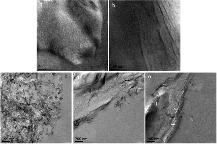 | ||
| Fig. 6 TEM images of the ultrathin section: (a) GO/EP, (b) EGO/EP, (c) CNT/EP, (d) GO-CNT/EP and (e) EGO-CNT/EP (the white arrows show that CNTs exist between the adjacent EGO sheets). | ||
3.3. Mechanical properties of epoxy composites
The tensile properties of EP, CNT/EP, GO/EP, EGO/EP, GO-CNT/EP and EGO-CNT/EP are shown in Fig. 7. It can be seen that the tensile strength, elastic modulus and elongation at break of GO/EP, EGO/EP, CNT/EP, GO-CNT/EP and EGO-CNT/EP are higher than those of EP, indicating the reinforcing effect of these fillers on epoxy matrix. This reinforcing effect is attributed to that carbon nanofillers bear the load and dissipate energy during the failure process of epoxy composite.49 When comparing the mechanical properties of GO/EP and EGO/EP, it is clear that EGO shows better reinforcing effect than GO. This is attributed to the fact that the improved interfacial interaction, compatibility and dispersion of EGO in epoxy matrix are achieved after functionalization (Fig. 6b), which are critical factors to the mechanical properties of epoxy composites.50,51 Notably, GO-CNT/EP exhibit better performance compared with epoxy composites reinforced by individual carbon nanofillers (CNT or GO), indicating the synergistic effect of GO-CNT on the improvement of the tensile properties of epoxy composites. Moreover, the more obvious synergistic effect can be found when comparing the tensile properties of EGO-CNT/EP with those of EGO/EP and CNT/EP. For example, EGO-CNT/EP reach the highest tensile strength, elastic modulus and elongation at break (87.5 MPa, 4012.3 MPa and 4.08%) and significantly increase by 43.6%, 38.1% and 55.1% compared with EP, which is much higher than those of epoxy composites reinforced by each individual filler (EGO or CNT). This synergistic effect may be explained by the following two aspects. Firstly, EGO-CNT overcomes the dispersion problem faced by the individual fillers (GO or CNT), forming the filler network structure with uniform filler dispersion in epoxy matrix (as shown in Fig. 6e). This makes EGO-CNT bear load more uniformly. Secondly, this 3D structure hybrids possess great advantages over traditional nanofillers: (i) the interfacial interaction between EGO-CNT and epoxy matrix may be improved due to the epoxy molecular chain grafted on EGO which can react with amine curing agent and therefore form covalent bonding with the epoxy matrix and link into the crosslinked molecular network (as shown in Scheme 1b). (ii) Due to the 3D structure, hybrids can form stronger interfacial interaction with epoxy matrix than traditional nanofillers.43,45,52,53 For example, Yang et al.43 found that CNTs can act as extended tentacles for the 3D structure hybrids and entangle with epoxy resin chain, resulting in better interfacial interaction. Thus, EGO-CNT can bear load more effectively. Further investigation on the tensile properties of GO-CNT/EP and EGO-CNT/EP shows that well compatibility and uniform dispersion of hybrids markedly enhance their synergistic effect on the improvement of tensile properties of epoxy composites.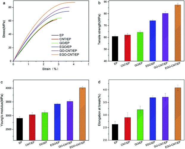 | ||
| Fig. 7 Tensile properties of epoxy composites at the filler content of 1 wt%: (a) representative stress–strain curves, (b) tensile strength, (c) elastic modulus and (d) elongation at break. | ||
The SENB test results of KIC and GIC of EP, CNT/EP, GO/EP, EGO/EP, GO-CNT/EP and EGO-CNT/EP are shown in Fig. 8. It shows that the KIC and GIC of epoxy composites are improved after adding different types of carbon nanofiller, showing different toughening effect. Comparing the KIC and GIC of GO/EP and EGO/EP, it can be found that EGO possesses better toughening effect than GO. This is due to the strong interfacial interaction between EGO and epoxy matrix due to the covalent bonding and well compatibility of EGO with epoxy matrix which endows EGO larger contact area. Furthermore, GO-CNT/EP and EGO-CNT/EP show higher values of KIC and GIC than epoxy composites reinforced by any individual carbon nanofillers (CNT, GO or EGO), indicating synergistic effect on the improvement of fracture toughness of epoxy composites. This synergistic effect on fracture toughness of epoxy matrix may be attributed to two factors. On the one hand, due to the co-dispersing effect, the hybrids show uniform dispersion which is beneficial for maximizing their nano-effect (such as extremely high specific surface area) to achieve better toughening effect.54 On the other hand, the strong interfacial interaction formed between 3D structure hybrids and epoxy matrix results in more energy dissipation during the failure process of epoxy composite, especially when the failure happens on the interface between hybrids and epoxy matrix. Particularly, the highest values of KIC and GIC are achieved by EGO-CNT/EP, which reach 1.24 MPa m1/2 and 336.3 J m−2 respectively and significantly increase by 85.1% and 148% compared with EP, showing the most excellent toughening effect of EGO-CNT. This indicates that well compatibility of EGO in hybrids enhances synergistic effect on the improvement of fracture toughness of epoxy matrix.
 | ||
| Fig. 8 Fracture properties of epoxy composites at the filler content of 1 wt%: (a) representative load–displacement curves, (b) KIC values and (c) GIC values. | ||
According to the above tensile and fracture properties of epoxy composites, we compare the data of elastic modulus (E), tensile strength (σ), fracture toughness (KIC) and critical energy release rate (GIC) of epoxy-based composites and the relative increasement after adding different carbon nanofillers, as shown in Table 1.16,29,34,43,48,55–60 All epoxy-based composites have a low filler content (0.24–1 wt%). Compared with other epoxy-based composites reported in literatures, the EGO/EP and EGO-CNT/EP in this work have good balance among elastic modulus (E), tensile strength (σ), fracture toughness (KIC) and critical energy release rate (GIC). Meanwhile, EGO-CNT/EP has the most balanced and excellent mechanical properties, followed by EGO/EP, and GO/EP exhibits relatively low mechanical performance. This indicates that every modification step (epoxy functionalization or EGO-CNT formation by π–π stacking interaction) used in this work contributes obviously on mechanical properties of epoxy composites and the overall modification is indeed an effective method to construct 3D structure hybrids which possess excellent reinforcing and toughening effects on epoxy composites.
| Filler type (content) | Increase in E [%] (E of matrix [MPa]) | Increase in σ [%] (σ of matrix [MPa]) | Gain in KIC [%] (KIC of matrix [MPa m1/2]) | Gain in GIC [%] (GIC of matrix [J m−2]) | References |
|---|---|---|---|---|---|
| GO (1 wt%) | 7.1 (2905) | 5.7 (60.9) | 26.9 (0.67) | 50.3 (135.6) | This work |
| EGO (1 wt%) | 17.9 (2905) | 21.8 (60.9) | 55.2 (0.67) | 104.4 (135.6) | |
| EGO-CNT (1 wt%) | 38.1 (2905) | 43.6 (60.9) | 85.1 (0.67) | 148 (135.6) | |
| Pristine CNT (0.34 wt%) | 19.4 (1340) | −12.3 (65) | 19.4 (0.67) | — | 55 |
| PEO-CNT (0.5 wt%) | 26.7 (3000) | 34.5 (58) | — | — | Polyethylenoxide wrapped CNT16 |
| CNT-NH2 (0.5 wt%) | 14.6 (2599) | 8.4 (63.8) | 43.1 (0.65) | — | 56 |
| Pristine GO (0.5 wt%) | 24 (2500) | 11.3 (69.7) | 24.5 (1.02) | 25 (360) | 57 |
| Pristine GO (1 wt%) | ∼6.3 (∼2400) | ∼20 (∼50) | — | — | 58 |
| NMP functionalized GO (0.5 wt%) | 17.5 (1287) | −12.7 (45.7) | 91.7 (1.2) | 215.3 (973) | N-Methyl-2-pyrrolidone functionalized GO59 |
| PEA-GO (0.5 wt%) | 9.5 (3150) | 51.3 (53) | — | — | Polyetheramine functionalized GO60 |
| HPEEK-g-GO (0.5 wt%) | 6.6 (61) | 31.2 (0.77) | — | Poly(ether ether ketone) functionalized GO34 | |
| GNP-CNT (0.5 wt%) | — | — | ∼90 (∼0.47) | — | GNP: graphene platelets29 |
| GO-CNT (0.24 wt%) | 12.1 (1650) | 13.6 (44) | — | — | 43 |
| MGP-CNT (1 wt%) | 22.6 (2646) | 14.5 (47.7) | — | — | MGP: multi-graphene platelets48 |
3.4. Fracture morphology and mechanism analysis
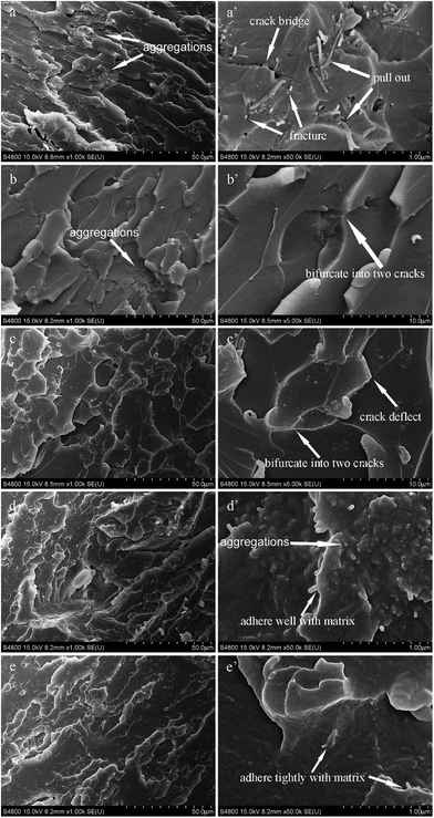
The fracture surfaces of tensile samples of CNT/EP, GO/EP, EGO/EP, GO-CNT/EP and EGO-CNT/EP are observed as shown in Fig. 9. From the fracture surface of CNT/EP (Fig. 9a and a′), there are many aggregations indicating poor dispersion and some gaps around CNT suggesting weak interfacial adhesion which may be attributed to the entanglements of CNTs. Meanwhile, it can be found from Fig. 9a′ that numerous long white lines and holes indicate that CNTs pulled out of epoxy matrix and some short white lines imply that CNTs first bridged the crack and then fractured, which are assumed to be the main failure mechanism of CNT. For GO/EP, many dimple morphologies can be observed (Fig. 9b) which is the typical facture morphology of graphene or graphene derivatives reinforced composites reported in previous literatures61–63 and some aggregations (Fig. 9b) with micrometer scale can also be found indicating poor dispersion. Comparatively, there are relatively more dimple morphologies without any aggregations in the fracture surface of EGO/EP (Fig. 9c). Moreover, most EGO are difficult to be distinguished suggesting good wrapping by epoxy matrix. All these facts indicate good dispersion, well compatibility of EGO in epoxy matrix and strong interfacial adhesion between EGO and epoxy matrix. In addition, it can be found from the high magnification of these dimples (Fig. 9b′ and c′) that the cracks are deflected or bifurcated when they encounter EGO (or GO).For GO-CNT/EP, there is a rougher fracture surface than any other epoxy composites reinforced by individual filler (CNT, GO or EGO) and a few aggregations still exist (Fig. 9d). This rough fracture surface reveals more complex failure mechanism in GO-CNT/EP, in which some dimple morphologies observed in Fig. 9d indicates crack deflection/bifurcation mechanism of GO meanwhile many short white lines (Fig. 9d′) suggest the mechanism of CNTs fracture and crack bridging. It is worth to note that most short white lines are observed around the dimples (Fig. 9d′). Thus, it is reasonable to say that GO may first deflect or bifurcate the cracks and then induce the cracks into the 3D structure filler network, facilitating the mechanisms of CNT fracture and crack bridging and leading to more tough fracture surface. This is assumed to be the key element for better reinforcing and toughening effects of GO-CNT than individual filler. Moreover, it can be seen that epoxy matrix adhere well with CNT, suggesting relatively strong interfacial adhesion between GO-CNT and epoxy matrix because of the unique 3D structure. For EGO-CNT/EP, although failure mechanisms are similar with GO-CNT/EP, most rough fracture surface without any aggregations can be observed (Fig. 9e) confirming that EGO-CNT achieved more obvious co-dispersing effect. Thus, the high degree of dispersion, compatibility and interfacial interaction of EGO-CNT hybrids through functionalization may build up a balanced 3D filler–filler network to promote both stress transferring and energy absorption under loading, leading to the excellent reinforcing and toughening effects.
The fracture surfaces of SENB samples of CNT/EP, GO/EP, EGO/EP, GO-CNT/EP and EGO-CNT/EP are observed as shown in Fig. S3.† It can be seen that the fracture surface of EGO-CNT/EP are most rough compared with other epoxy composites. This confirms that EGO-CNT possess the most excellent reinforcing and toughening effects compared with other epoxy composites (CNT/EP, GO/EP, EGO/EP and GO-CNT/EP).
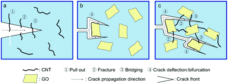
According to the failure mechanism of different carbon nanofillers observed in Fig. 9, the failure mechanisms of individual filler and the hybrids in ideal dispersion state are further revealed. The schematics are shown in Fig. 10. As shown in Fig. 10a, when the crack front encounters CNT, pull out and bridging, fracture contribute to major failure mechanisms of CNT which may depend on the interfacial adhesion property and also the CNT length.64 For GO, the crack front is initially pinned to the GO and bifurcates the GO, then continuing to propagate around the GO (Fig. 10b). Notably, the height level of the bifurcated cracks may be different, which can be confirmed by Fig. 9b and c showing different height levels on the fracture plane. Similar result has also been found by Quaresimin.61 This make the crack path torturous and dissipate much energy, lead to improved mechanical properties of epoxy composites. For the hybrids (GO-CNT and EGO-CNT), there are more complex mechanisms containing crack bridging, CNT fracture and crack deflection/bifurcation than individual carbon nanofillers. In the 3D structure filler network, the mechanism of crack deflection/bifurcation induced by EGO (or GO) make the crack path torturous and the amount of crack path increase. This allows the cracks encounter more CNTs in different height levels and therefore the mechanisms of CNT fracture and bridging are promoted during the crack propagation, resulting in more energy dissipation and good reinforcing and toughening effects. The above failure mechanisms are all based on the condition of good dispersion state of fillers. However, the poor dispersion state of fillers in epoxy matrix, such as aggregations formed in epoxy matrix (Fig. 6c), may cause stress concentration during loading and then lead to premature failure, severely affecting their load bearing efficiency.65,66 Therefore, it is essential to achieve good dispersion state of fillers. The hybrids prepared by combining EGO and CNT (EGO-CNT) achieves uniform dispersion state in epoxy matrix, avoiding premature failure due to aggregations and other undesirable failure mechanisms and maximizing its load bearing efficiency. Thus EGO-CNT possess the excellent reinforcing and toughening effects.
The CNT length is also an important factor affecting its failure mechanism.64,67–69 In this paper, the fabrication process including the high speed mechanical stirring and sonication treatment inevitably leads to the shorten of CNTs.70,71 According to previous literatures, the CNTs shorter than lc should be pulled out of polymer matrix during composite fracture; otherwise, they tend to be fracture.64 Therefore, it is necessary to find lc in order to estimate the influence of shorten of CNTs in this work on mechanical properties and toughening mechanisms. Wagner et al.67 proposed a modified Cottrell–Kelly–Tyson (CKT) model which can be used for calculate the critical length of CNTs. According to the proposed theory, the critical length of CNTs is given by the following equation:
 | (3) |
4. Conclusions
In this work, epoxy resin was utilized for GO functionalization and 3D structure hybrids by combining 1D CNT and 2D functionalized GO were prepared. The resulting EGO-CNT showed obvious co-dispersing effect in epoxy matrix due to well compatibility. The tensile and SENB tests results indicated enhanced tensile strength (43.6% increase), elastic modulus (38.1% increase), KIC (85.1% increase) and GIC (148% increase) for the EGO-CNT/EP compared with EP, revealing a synergistic effect on the improvement of mechanical properties of epoxy composites. The fracture surface analysis demonstrated that EGO-CNT achieve strong interfacial interaction with epoxy matrix which may be due to the covalent bonds formed between the epoxy molecular chain grafted on EGO and hardener agent during curing process. Moreover, the mechanism analysis revealed that the crack deflection/bifurcation mechanism induced by EGO makes the crack propagation path be more tortuous and increases the number of micro-cracks. This increases the probability of cracks passing through CNTs and thereby promotes bridging and fracture of CNTs, maximizes the utilization of CNTs in the filler network and dissipates more energy. This is the key mechanism for the excellent reinforcing and toughening effects achieved by 3D structure hybrids.Conflicts of interest
There are no conflicts to declare.Acknowledgements
This work was supported by the National Natural Science Foundation of China (51708553). The authors also wish to express their sincere thanks to Prof. Xupu Yang for the help with the test of mechanical properties.References
- M. M. J. Treacy, T. W. Ebbesen and J. M. Gibson, Nature, 1996, 381, 678–680 CrossRef CAS.
- Ç. T. CheJianwei and W. A. Goddard III, Nanotechnology, 2000, 11, 2083–2085 Search PubMed.
- T. W. Ebbesen, H. J. Lezec, H. Hiura, J. W. Bennett, H. F. Ghaemi and T. Thio, Nature, 1996, 382, 54–56 CrossRef CAS.
- F. H. Gojny, M. H. G. Wichmann, U. Köpke, B. Fiedler and K. Schulte, Compos. Sci. Technol., 2004, 64, 2363–2371 CrossRef CAS.
- S. U. Khan, J. R. Pothnis and J.-K. Kim, Composites, Part A, 2013, 49, 26–34 CrossRef CAS.
- T. x. Liu, I. Y. Phang, L. Shen, S. Y. Chow and W.-D. Zhang, Macromolecules, 2004, 37, 7214–7222 CrossRef CAS.
- Z. Chen, X. J. Dai, K. Magniez, P. R. Lamb, D. Rubin de Celis Leal, B. L. Fox and X. Wang, Composites, Part A, 2013, 45, 145–152 CrossRef CAS.
- H. Yu, J. Liu, X. Wen, Z. Jiang, Y. Wang, L. Wang, J. Zheng, S. Fu and T. Tang, Polymer, 2011, 52, 4891–4898 CrossRef CAS.
- E. Y. Choi, L. W. Choi and C. K. Kim, Carbon, 2015, 95, 91–99 CrossRef CAS.
- J. Ryu and M. Han, Compos. Sci. Technol., 2014, 102, 169–175 CrossRef CAS.
- Q. Li, M. Zaiser, J. R. Blackford, C. Jeffree, Y. He and V. Koutsos, Mater. Lett., 2014, 125, 116–119 CrossRef CAS.
- T. P. Chua, M. Mariatti, A. Azizan and A. A. Rashid, Compos. Sci. Technol., 2010, 70, 671–677 CrossRef CAS.
- A. Garg and S. B. Sinnott, Chem. Phys. Lett., 1998, 295, 273–278 CrossRef CAS.
- X. Peng and S. S. Wong, Adv. Mater., 2009, 21, 625–642 CrossRef CAS.
- N. G. Sahoo, S. Rana, J. W. Cho, L. Li and S. H. Chan, Prog. Polym. Sci., 2010, 35, 837–867 CrossRef CAS.
- J. M. Gonzalez-Dominguez, M. A. Tesa-Serrate, A. Anson-Casaos, A. M. Diez-Pascual, M. A. Gomez-Fatou and M. T. Martinez, J. Phys. Chem. C, 2012, 116, 7399–7408 CrossRef CAS.
- A. Mandal and A. K. Nandi, J. Phys. Chem. C, 2012, 116, 9360–9371 CrossRef CAS.
- A. Ghosh, K. V. Rao, R. Voggu and S. J. George, Chem. Phys. Lett., 2010, 488, 198–201 CrossRef CAS.
- J. W. Suk, R. D. Piner, J. An and R. S. Ruoff, ACS Nano, 2010, 4, 6557–6564 CrossRef CAS PubMed.
- D. R. Dreyer, S. Park, C. W. Bielawski and R. S. Ruoff, Chem. Soc. Rev., 2010, 39, 228–240 RSC.
- S. Srivastava, V. Kumar, M. A. Ali, P. R. Solanki, A. Srivastava, G. Sumana, P. S. Saxena, A. G. Joshi and B. D. Malhotra, Nanoscale, 2013, 5, 3043–3051 RSC.
- L. Tian, M. J. Meziani, F. Lu, C. Y. Kong, L. Cao, T. J. Thorne and Y. P. Sun, ACS Appl. Mater. Interfaces, 2010, 2, 3217–3222 CrossRef CAS PubMed.
- C. Zhang, L. Ren, X. Wang and T. Liu, J. Phys. Chem. C, 2010, 114, 11435–11440 CrossRef CAS.
- J. Kim, L. J. Cote, F. Kim, W. Yuan, K. R. Shull and J. Huang, J. Am. Chem. Soc., 2010, 132, 8180 CrossRef CAS PubMed.
- B. Shen, W. Zhai, M. Tao, D. Lu and W. Zheng, Compos. Sci. Technol., 2013, 77, 87–94 CrossRef CAS.
- M. Cano, U. Khan, T. Sainsbury, A. O'Neill, Z. Wang, I. T. McGovern, W. K. Maser, A. M. Benito and J. N. Coleman, Carbon, 2013, 52, 363–371 CrossRef CAS.
- Y. Lin, J. Jin and M. Song, J. Mater. Chem., 2011, 21, 3455–3461 RSC.
- H. K. Cheng, N. G. Sahoo, Y. P. Tan, Y. Pan, H. Bao, L. Li, S. H. Chan and J. Zhao, ACS Appl. Mater. Interfaces, 2012, 4, 2387–2394 CrossRef CAS PubMed.
- S. Chatterjee, F. Nafezarefi, N. H. Tai, L. Schlagenhauf, F. A. Nüesch and B. T. T. Chu, Carbon, 2012, 50, 5380–5386 CrossRef CAS.
- H. Im and J. Kim, Carbon, 2012, 50, 5429–5440 CrossRef CAS.
- W. S. Hummers and R. E. Offeman, J. Am. Chem. Soc., 1958, 80, 1339 CrossRef CAS.
- H. Mahmood, M. Tripathi, N. Pugno and A. Pegoretti, Compos. Sci. Technol., 2016, 126, 149–157 CrossRef CAS.
- Z. Qi, Y. Tan, H. Wang, T. Xu, L. Wang and C. Xiao, Polym. Test., 2017, 64, 38–47 CrossRef CAS.
- P. Katti, K. V. Kundan, S. Kumar and S. Bose, Polymer, 2017, 122, 184–193 CrossRef CAS.
- P. K. S. Mural, A. Banerjee, M. S. Rana, A. Shukla, B. Padmanabhan, S. Bhadra, G. Madras and S. Bose, J. Mater. Chem. A, 2014, 2, 17635–17648 RSC.
- C.-C. Teng, C.-C. M. Ma, C.-H. Lu, S.-Y. Yang, S.-H. Lee, M.-C. Hsiao, M.-Y. Yen, K.-C. Chiou and T.-M. Lee, Carbon, 2011, 49, 5107–5116 CrossRef CAS.
- S. Park and R. S. Ruoff, Nat. Nanotechnol., 2009, 4, 217 CrossRef CAS PubMed.
- B. R. C. de Menezes, F. V. Ferreira, B. C. Silva, E. A. N. Simonetti, T. M. Bastos, L. S. Cividanes and G. P. Thim, J. Mater. Sci., 2018, 53, 14311–14327 CrossRef CAS.
- F. V. Ferreira, B. R. C. D. Menezes, G. P. N. Thim, E. A. Nunes Simonetti, L. D. S. Cividanes, F. S. Brito and W. Franceschi, Functionalizing Graphene and Carbon Nanotubes –A Review, Springer International Publishing, 1 edn, 2017 Search PubMed.
- L. Zhang, Y. Huang, Y. Zhang, W. Fan and T. Liu, ACS Appl. Mater. Interfaces, 2015, 7, 27823–27830 CrossRef CAS PubMed.
- A.C. Ferrari, J.C. Meyer, V. Scardaci, C. Casiraghi, M. Lazzeri, F. Mauri, S. Piscanec, D. Jiang, K.S. Novoselov and S. Roth, Phys. Rev. Lett., 2006, 97, 187401 CrossRef CAS PubMed.
- A. Maio, R. Fucarino, R. Khatibi, S. Rosselli, M. Bruno and R. Scaffaro, Compos. Sci. Technol., 2015, 119, 131–137 CrossRef CAS.
- S.-Y. Yang, W.-N. Lin, Y.-L. Huang, H.-W. Tien, J.-Y. Wang, C.-C. M. Ma, S.-M. Li and Y.-S. Wang, Carbon, 2011, 49, 793–803 CrossRef CAS.
- J. Y. Oh, G. H. Jun, S. Jin, H. J. Ryu and S. H. Hong, ACS Appl. Mater. Interfaces, 2016, 8, 3319–3325 CrossRef CAS PubMed.
- J. Wang, X. Jin, H. Wu and S. Guo, Carbon, 2017, 123, 502–513 CrossRef CAS.
- Y. Li, T. Yang, T. Yu, L. Zheng and K. Liao, J. Mater. Chem., 2011, 21, 10844–10851 RSC.
- C. Zhang, S. Huang, W. W. Tjiu, W. Fan and T. Liu, J. Mater. Chem., 2012, 22, 2427–2434 RSC.
- Y. Li, R. Umer, A. Isakovic, Y. A. Samad, L. Zheng and K. Liao, RSC Adv., 2013, 3, 8849–8856 RSC.
- F. V. Ferreira, W. Franceschi, B. R. C. Menezes, F. S. Brito, K. Lozano, A. R. Coutinho, L. S. Cividanes and G. P. Thim, Appl. Surf. Sci., 2017, 410, 267–277 CrossRef CAS.
- C. Bao, Y. Guo, L. Song, Y. Kan, X. Qian and Y. Hu, J. Mater. Chem., 2011, 21, 13290 RSC.
- I. F. Pinheiro, F. V. Ferreira, D. H. S. Souza, R. F. Gouveia, L. M. F. Lona, A. R. Morales and L. H. I. Mei, Eur. Polym. J., 2017, 97, 356–365 CrossRef CAS.
- N. H. Kim, T. Kuila and J. H. Lee, J. Mater. Chem. A, 2014, 2, 2681–2689 RSC.
- J.-K. Wu, C.-C. Ye, T. Liu, Q.-F. An, Y.-H. Song, K.-R. Lee, W.-S. Hung and C.-J. Gao, Mater. Des., 2017, 119, 38–46 CrossRef CAS.
- N. Domun, H. Hadavinia, T. Zhang, T. Sainsbury, G. H. Liaghat and S. Vahid, Nanoscale, 2015, 7, 10294–10329 RSC.
- N. Lachman and H. Daniel Wagner, Composites, Part A, 2010, 41, 1093–1098 CrossRef.
- F. Gojny, M. Wichmann, B. Fiedler and K. Schulte, Compos. Sci. Technol., 2005, 65, 2300–2313 CrossRef CAS.
- Z. Li, R. Wang, R. J. Young, L. Deng, F. Yang, L. Hao, W. Jiao and W. Liu, Polymer, 2013, 54, 6437–6446 CrossRef CAS.
- B. Ahmadi-Moghadam, M. Sharafimasooleh, S. Shadlou and F. Taheri, Mater. Des., 2015, 66, 142–149 CrossRef CAS.
- S. Chhetri, N. C. Adak, P. Samanta, N. C. Murmu and T. Kuila, Polym. Test., 2017, 63, 1–11 CrossRef CAS.
- L.-Z. Guan, Y.-J. Wan, L.-X. Gong, D. Yan, L.-C. Tang, L.-B. Wu, J.-X. Jiang and G.-Q. Lai, J. Mater. Chem. A, 2014, 2, 15058–15069 RSC.
- M. Quaresimin, K. Schulte, M. Zappalorto and S. Chandrasekaran, Compos. Sci. Technol., 2016, 123, 187–204 CrossRef CAS.
- S. Chandrasekaran, N. Sato, F. Tölle, R. Mülhaupt, B. Fiedler and K. Schulte, Compos. Sci. Technol., 2014, 97, 90–99 CrossRef CAS.
- Y.-J. Wan, L.-C. Tang, L.-X. Gong, D. Yan, Y.-B. Li, L.-B. Wu, J.-X. Jiang and G.-Q. Lai, Carbon, 2014, 69, 467–480 CrossRef CAS.
- L.-c. Tang, H. Zhang, J.-h. Han, X.-p. Wu and Z. Zhang, Compos. Sci. Technol., 2011, 72, 7–13 CrossRef CAS.
- M. M. Shokrieh, S. M. Ghoreishi, M. Esmkhani and Z. Zhao, Fatigue Fract. Eng. Mater. Struct., 2014, 37, 1116–1123 CrossRef CAS.
- L.-C. Tang, Y.-J. Wan, D. Yan, Y.-B. Pei, L. Zhao, Y.-B. Li, L.-B. Wu, J.-X. Jiang and G.-Q. Lai, Carbon, 2013, 60, 16–27 CrossRef CAS.
- H. D. Wagner, P. M. Ajayan and K. Schulte, Compos. Sci. Technol., 2013, 83, 27–31 CrossRef CAS.
- S.-Y. Fu, Z.-K. Chen, S. Hong and C. C. Han, Carbon, 2009, 47, 3192–3200 CrossRef CAS.
- H. Wan, F. Delale and L. Shen, Mech. Res. Commun., 2005, 32, 481–489 CrossRef.
- J. Zhou, J. Cheiftz, R. Li, F. Wang, X. Zhou, T.-K. Sham, X. Sun and Z. Ding, Carbon, 2009, 47, 829–838 CrossRef CAS.
- M. Kierkowicz, E. Pach, A. Santidrián, S. Sandoval, G. Gonçalves, E. Tobías-Rossell, M. Kalbáč, B. Ballesteros and G. Tobias, Carbon, 2018, 139, 922–932 CrossRef CAS.
Footnote |
| † Electronic supplementary information (ESI) available. See DOI: 10.1039/c8ra08312f |
| This journal is © The Royal Society of Chemistry 2018 |

