DOI:
10.1039/C8RA07438K
(Paper)
RSC Adv., 2018,
8, 34699-34711
Effect of Bi3+ ion on upconversion-based induced optical heating and temperature sensing characteristics in the Er3+/Yb3+ co-doped La2O3 nano-phosphor
Received
6th September 2018
, Accepted 29th September 2018
First published on 9th October 2018
Abstract
The upconversion-based optical heating and temperature sensing characteristics are investigated in the Er3+/Yb3+/Bi3+ tri-doped La2O3 nano-phosphor synthesized through a solution combustion method. The structural measurements reveal an increase in lattice parameters and particles size of the phosphor on increasing the concentrations of Bi3+ ions. The energy dispersive spectroscopic (EDS) measurements confirm the presence of La, Er, Yb, Bi and O elements in the tri-doped phosphor. The absorption spectra show the large number of bands due to Er3+, Yb3+ and Bi3+ ions. The Er3+/Yb3+ co-doped phosphor gives strong green emission bands at 523 and 548 nm upon 976 nm excitation due to 2H11/2 → 4I15/2 and 4S3/2 → 4I15/2 transitions of Er3+ ion, respectively. The emission intensity of these bands is enhanced upto 15 times in the presence of Bi3+ ions. The emission intensities of the 523 and 548 nm bands vary non-linearly with the pump power. The fluorescence intensity ratio (FIR) of the thermally coupled 523 and 548 nm emission bands shows efficient optical heating in the tri-doped phosphor. The FIR of the 523 and 548 nm emission bands further varies with the increase in temperature of the phosphor. The relative temperature sensing sensitivity has been calculated to be 71 × 10−4 K−1 at 450 K for the tri-doped phosphor. Thus, the Er3+/Yb3+/Bi3+ tri-doped La2O3 nano-phosphor may provide a platform to use it in the photonic devices, as an optical heater and temperature sensor.
1. Introduction
Upconversion-based lanthanide spectroscopic studies have become a fascinating area of research in recent years due to its wide applications in various related fields, such as optical devices, optical heaters, photo-thermal treatment, temperature sensors, bio-imaging, etc.1–9 The thermally coupled energy levels in some of the lanthanide ions are of great scientific importance as they can sense a small change in the temperature around them even at a distance without any contact.4–6,10 These thermally coupled energy levels produce optical heating as well as being used for temperature sensing in the lanthanide doped phosphor materials. Er3+ is one such lanthanide ion, which contains thermally coupled energy levels viz. 2H11/2 and 4S3/2 levels, separated by an energy gap of 800 cm−1. This energy gap can be covered by the phonon energy of the host lattice.4–6,11 The population of the ions in these two levels strongly depends on the phonon energy of the host. Thus, this causes a variation in intensity of the emitted bands from the thermally coupled levels in the Er3+/Yb3+ co-doped phosphor materials with increase in the pump power and temperature, thereby gives a dual characteristic such as optical heating and temperature sensing.
The optical properties of the Er3+/Yb3+ co-doped phosphor materials have been studied in detail by different groups.12–20 They have reported intense green and weak red upconverted emissions upon 976 nm excitation in which the green emission arises due to the transition from the thermally coupled energy levels (viz. 2H11/2 and 4S3/2) to the ground level (4I15/2) of Er3+ ion. Since the two levels are thermally coupled, therefore, they can sense a variation as the input pump power of 976 nm source is changed. The emission intensity of one level increases whereas that of the other level decreases with the increase in the pump power. Therefore, the emission intensity ratio of the peaks arising from these levels, so called the fluorescence intensity ratio (FIR), is a measure of induced optical heating in the phosphor materials. The FIR of the peaks also varies with the increase in temperature of the sample. The optical heating and temperature sensing abilities of the Er3+/Yb3+ co-doped phosphors have also been investigated in different host materials.4–6,11,19,21–23 They have reported that the FIR is host dependent and the material with low phonon frequency can sustain better FIR with the pump power and temperature.
The research efforts are still continued to develop materials to improve the optical heating and temperature sensing abilities of the Er3+/Yb3+ co-doped phosphor materials. Some ions, such as Ho3+, Li+, Zn2+, Eu3+, etc. play a dynamic role for improving these characteristics when incorporated in the co-doped phosphors.13,24–26 These ions modify local crystal field around the lanthanide ions in such a way that they give relatively larger upconversion/fluorescence emission intensities on excitation with a near infrared (NIR) source. The effect of Li+ ion on optical heating and temperature sensing has been studied in the Er3+/Yb3+ co-doped Y2Ti2O7 phosphor and observed an enhancement in the emission intensity.24 The enhanced intensity from the Er3+ ion yields better FIR with the increase in the laser pump powers and temperatures. Mahata et al. have also reported the effect of Zn2+ in the Er3+/Yb3+ co-doped BaTiO3 phosphor and found improved properties of these characters.25 The emission intensity of the Er3+/Yb3+ co-doped Y2O3 phosphor is also affected by incorporating Eu3+ ion in it.26 The variation in the emission intensity alters the temperature sensing ability of the phosphor due to its energy transfer rate. Choudhary et al. have reported the effect of Bi3+ ion on the optical heating and temperature sensing in the Er3+/Yb3+ co-doped MgAl2O4 phosphor.27 However, the effect of Bi3+ ion on the optical heating and temperature sensing characteristics have not been studied in the Er3+/Yb3+ co-doped La2O3 phosphor to our knowledge.
In this paper, the La2O3 has been used as a host material due to its low phonon energy (∼400–650 cm−1). The low phonon energy host strongly supports the radiative transitions by reducing non-radiative relaxations.8,11,24 It is a very stable host, which can broaden the operating range and can be used for low and high temperature sensing. The Er3+ and Yb3+ have been used as lanthanide ions in which the Er3+ ion contains thermally coupled energy levels, which senses a slight change in the incident pump power and temperature. The Bi3+ ion has been incorporated in the co-doped phosphor to maintain strong crystal structure around the Er3+ ions. The Bi3+ is an interesting metal ion, which acts as sensitizer and activator and emits light ranging from UV to IR, even in mid-IR. The Bi based materials contain low phonon energy, which can reduce non-radiative transition rate significantly and favors upconversion.28–30 The increase in laser pump power leads to a difference in the emission intensities of the bands arising from the thermally coupled levels (viz. 2H11/2 and 4S3/2). The FIR increases with the increase in the laser pump powers and also the sample temperatures. The Er3+/Yb3+/Bi3+ tri-doped La2O3 nano-phosphor is found to give very efficient induced optical heating and temperature sensing characteristics. This phosphor may open a new door for the study of optical heating and temperature sensing with a wide range of laser pump powers and temperatures.
2. Experimental
2.1 Materials and method
The Er3+/Yb3+/xBi3+ tri-doped La2O3 nano-phosphor samples with x = 0, 5, 10, and 15 mol% were synthesized through a solution combustion method. The concentrations of Er3+ and Yb3+ ions are fixed at 0.7 and 3.0 mol%, respectively. The La2O3, Er2O3, Yb2O3 and Bi2O3 with 99.99% purity were used as starting materials. Urea has been used as a fuel for combustion. These materials were weighed in their stoichiometric ratios and dissolved in 5 ml of nitric acid. The solution thus obtained was diluted using de-ionized water under constant stirring followed by drop wise addition of urea. The final solution was stirred in a beaker at 60 °C until a homogeneous sticky gel was obtained and the water contents evaporate from the solution. The final product thus obtained was placed in a closed furnace maintained at a constant temperature (∼600 °C) for combustion. Various gases (CO2, N2, etc.) were released from the gel due to the exothermic reaction during combustion. As a result, the white fluffy powder was obtained. It was grinded further to get the fine powder. The phosphor was finally annealed at 1300 °C to improve the structural and optical properties of the samples. The annealed phosphors have been used for further measurements.
2.2 Characterization
The crystalline phase, crystallinity and crystal strain in the samples have been analyzed using X-ray diffraction (XRD) technique. The XRD patterns of the samples have been recorded using Cu, Kα radiation (λ = 0.15406 nm) from a MiniFlex 600 (Rigaku, Japan) unit at 2° min−1 scan speed. The Rietveld analysis of the XRD patterns of the samples was performed using FullProf Suite.31 The scanning electron microscope (SEM) has been used to record the morphological features of the samples with a Zeiss, Evo 18 Research unit. The elemental analysis of the samples was carried out using the energy dispersive spectroscopic (EDS) measurements. The Fourier transform infrared (FTIR) measurements of the phosphor samples were carried out using a Perkin Elmer IR spectrometer (FT-IR/FIR Frontier spectrometer) to verify different molecules present in the samples. The upconversion spectra of the phosphor samples have been monitored using 976 nm excitation from a diode laser and an iHR320, Horiba Jobin Yvon, monochromator attached with PMT (photomultiplier tube) at various input pump powers and temperatures.
3. Results and discussion
3.1 Structural analysis
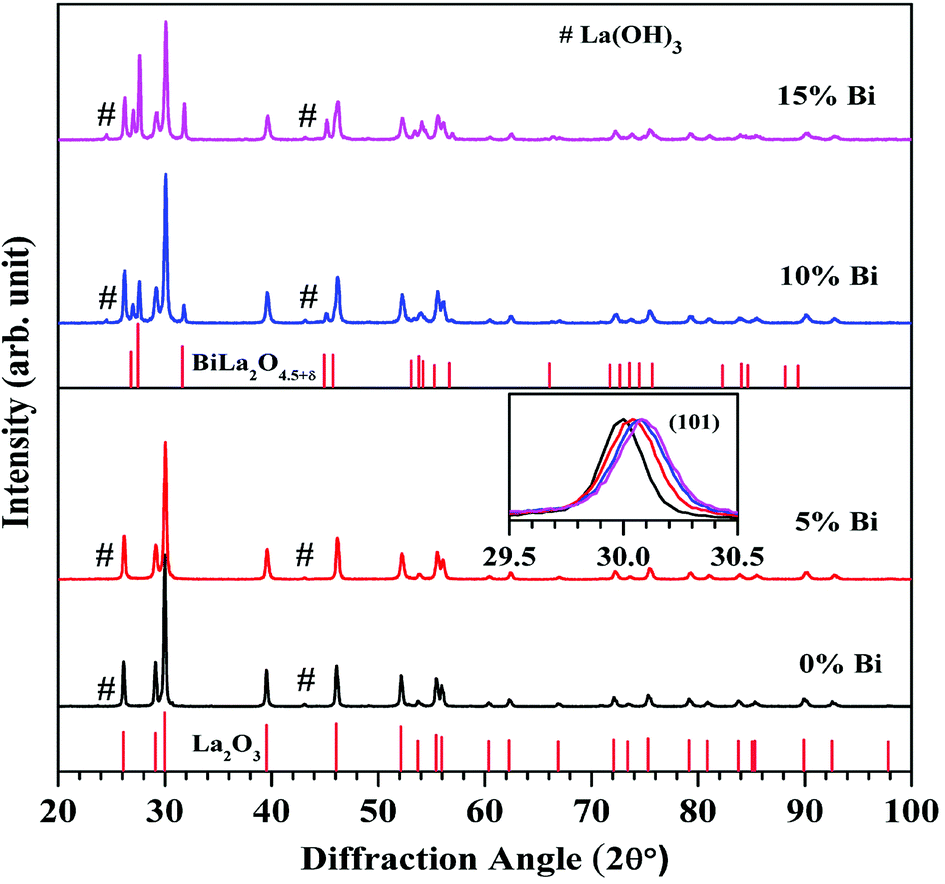
3.1.1 X-ray diffraction measurements. The room temperature X-ray diffraction (XRD) patterns of the Er3+/Yb3+/xBi3+ tri-doped La2O3 nano-phosphor samples for different concentrations of Bi3+ ions (i.e. x = 0, 5, 10, and 15 mol%) were recorded in the 2θ range of 20–100° and they are shown in Fig. 1. It is found that the XRD patterns of the samples in absence and presence of 5 mol% concentrations of Bi3+ ions confirm the formation of a single phase of the hexagonal crystal structure of La2O3 with JCPDS File no. 05-0602 and space group P![[3 with combining macron]](https://www.rsc.org/images/entities/char_0033_0304.gif) m1. Since the La2O3 is hygroscopic in nature, therefore, it absorbs moisture present in the atmosphere.8 Due to this, a small amount of La(OH)3 phase with JCPDS file no. 13-0084 is also present in the XRD patterns (peaks marked by #). However, the phase of La2O3 is dominant over the La(OH)3 phase. When the concentrations of Bi3+ ions are increased to 10 and 15 mol% a small amount of an additional rhombohedral phase of BiLa2O4.5+δ is also observed with JCPDS file no. 89-8058 and space group Rm. The inset in Fig. 1 indicates selected XRD peak (101) in the 2θ range of 29.5–30.5° in all the cases. The XRD peak (101) is shifted towards higher angle side with increasing concentrations of Bi3+ ions, which indicates a decrease in lattice parameters (lattice constants and unit cell volume). This was also confirmed by Rietveld refinement analysis of the phosphor samples.31
m1. Since the La2O3 is hygroscopic in nature, therefore, it absorbs moisture present in the atmosphere.8 Due to this, a small amount of La(OH)3 phase with JCPDS file no. 13-0084 is also present in the XRD patterns (peaks marked by #). However, the phase of La2O3 is dominant over the La(OH)3 phase. When the concentrations of Bi3+ ions are increased to 10 and 15 mol% a small amount of an additional rhombohedral phase of BiLa2O4.5+δ is also observed with JCPDS file no. 89-8058 and space group Rm. The inset in Fig. 1 indicates selected XRD peak (101) in the 2θ range of 29.5–30.5° in all the cases. The XRD peak (101) is shifted towards higher angle side with increasing concentrations of Bi3+ ions, which indicates a decrease in lattice parameters (lattice constants and unit cell volume). This was also confirmed by Rietveld refinement analysis of the phosphor samples.31
 |
| | Fig. 1 Room temperature XRD patterns of the Er3+/Yb3+/xBi3+ tri-doped La2O3 nano-phosphor samples for different concentrations of Bi3+ ions (i.e. x = 0, 5, 10, and 15 mol%). The inset shows a shift in the XRD peak (101) towards higher angle side with increasing the concentrations of Bi3+ ions. | |
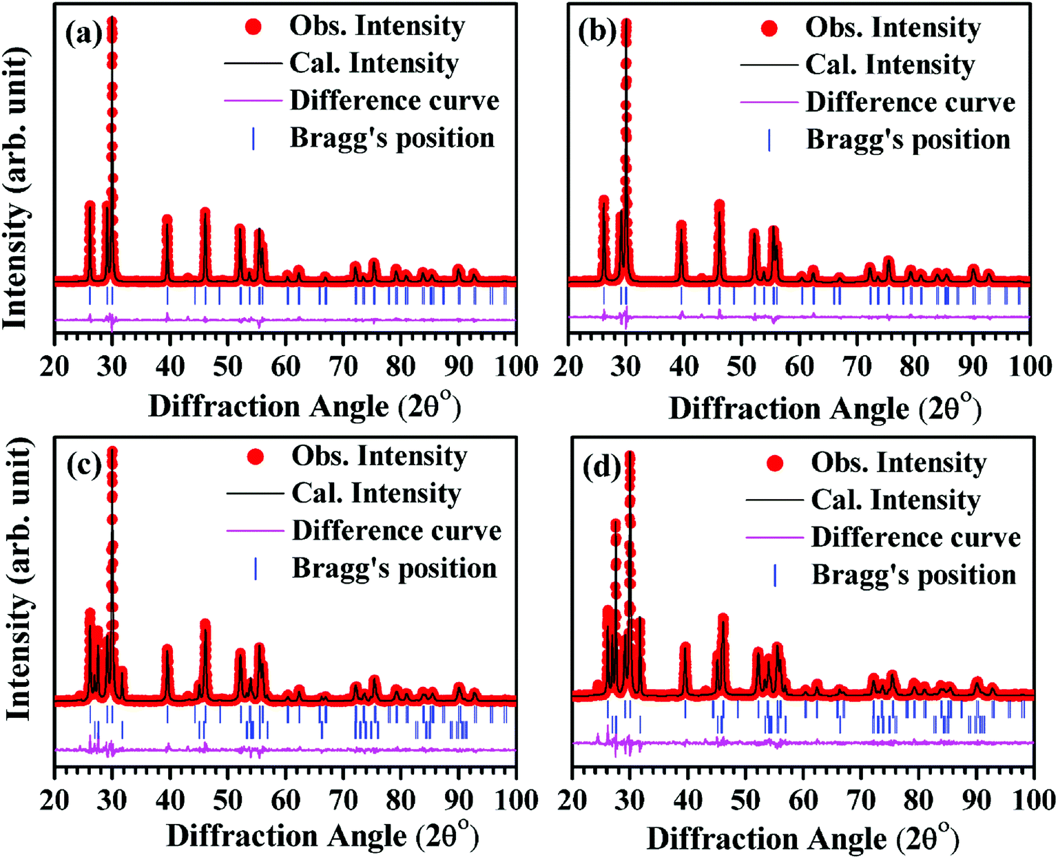
For structural refinement, we selected pseudo-Voigt function to fit the XRD profiles, while the background of the patterns was modeled using linear interpolation method between the selected background points. In hexagonal phase of space group Pm1, we consider substitution of La3+/(0.7)Er3+/(3.0)Yb3+/(0–15)Bi3+ ions at site 2(d) (1/3, 2/3, δz), O2−(1) ions at site 2(d) (1/3, 2/3, 1/2 + δz) and O2−(2) ions at site 1(a) (0, 0, 0).32 During the structure refinement of second phase using rhombohedral crystal structure with Rm space group, we consider hexagonal setting in which the La3+/(10–15) Bi3+ ions occupy at site 3(a) (0, 0, 0), O2−(1) ions occupy at site (3a) (0, 0, δz) and O2−(2) ions occupy at site 3(a) (0, 0, 1/2 + δz).33 Fig. 2(a–d) show Rietveld fits of the XRD patterns for different samples.
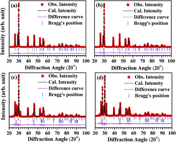 |
| | Fig. 2 Rietveld refined patterns for the nano-phosphor samples with different concentrations of Bi3+ ions i.e. (a) 0 mol% (b) 5 mol% (c) 10 mol% and (d) 15 mol% at La3+ site. | |
In Rietveld fit, the circular solid points indicate an experimental data observed from the X-ray diffractometer, while the continuous solid line just overlapping the observed patterns shows calculated XRD profile. The lower continuous curve indicates difference between the observed and the calculated patterns, which clearly shows a very good fit between the patterns. The vertical bars represent the position of Bragg's reflections. The obtained Rietveld refined lattice parameters are summarized in Table 1. The lattice constant “a” decreases from a = b = 3.9356(1) Å to a = b = 3.9322(1) Å and the constant “c” also decreases from 6.1306(2) Å to 6.1277(3) Å, while the unit cell volume decreases from V = 82.233(2) Å3 to V = 82.053(6) Å3 in absence and presence of 15 mol% concentrations of Bi3+ ions for the space group Pm1, respectively. In the case of space group Rm, the refined lattice parameters also decrease with increasing concentrations of Bi3+ ions. The obtained refined lattice parameters were fitted using exponentially decaying function and found in a good agreement between the obtained and the fitted values. Fig. 3 reveals a variation of lattice parameters as a function of doping contents of Bi3+ ions for the space group Pm1. The lattice constant “a” varies according to the following expression:
where
a0 and
a1 are fitting constants with values 3.9323(1) Å and 0.003(2) Å, respectively;
t is a decaying constant with its value 0.022(4) and
x is the concentrations of Bi
3+ ions. The lattice constant “
c” decreases exponentially with the following equation:
c = c0 + c1![[thin space (1/6-em)]](https://www.rsc.org/images/entities/char_2009.gif) e(−x/t) e(−x/t) |
where,
c0 and
c1 are fitting constants with values 6.127(5) Å and 0.004(5) Å, respectively and decaying constant (
t) is 0.08(3). The unit cell volume varies with the concentrations of Bi
3+ ions according to the expression:
| V = V0 + V1e(−x/t) |
where,
V0 and
V1 are fitting parameters with values
V0 = 82.054(4) Å
3,
V1 = 0.178(6) Å
3, respectively and
t is decaying constant with
t = 0.031(4). The average values of crystallite size and lattice strain for the Bi
3+ doped La
3+/Er
3+/Yb
3+ nano-phosphor samples have been estimated using Williamson–Hall (W–H) method. The W–H plot method is expressed by the following equation:
| βhklcosθhkl = 0.89λ/d + 4εsinθhkl |
where,
βhkl is full width at half maxima (FWHM) for (
hkl) peak,
d is the average value of crystallite size,
λ is the wavelength of radiation used in XRD measurement (
λ = 1.5406 Å),
ε is average value of lattice strain and
θhkl is Bragg's angle for (
hkl) reflection.
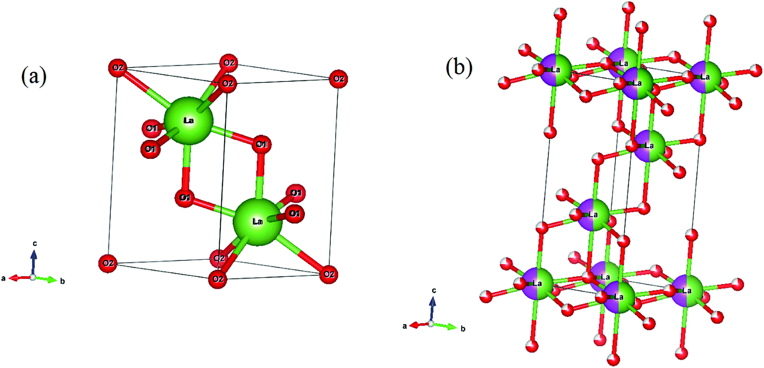
34 Ball and Stick models of the unit cells for space groups (a)
Pm1 and (b)
Rm have been drawn to see the arrangement of lanthanum and oxygen atoms (see
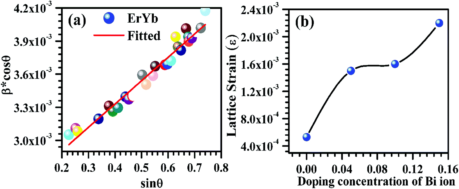
Fig. 4). A representative W–H plot for the Er
3+/Yb
3+ co-doped La
2O
3 phosphor sample is shown in
Fig. 5(a). The average values of crystallite size have been calculated and are found to be 55.9, 65.1, 66.3 and 88.9 nm for the 0, 5, 10 and 15 mol% concentrations of Bi
3+ ions in the nano-phosphor samples, respectively for La
2O
3 phase with space group
Pm1. The crystallite size increases with increasing the concentrations of Bi
3+ ions. The average values of the lattice strain increases from 5.3 × 10
−4 to 2.2 × 10
−3 for the concentrations of Bi
3+ ions from 0 to 15 mol%, respectively. The variation in lattice strain for the La
2O
3 phase as a function of different concentrations of Bi
3+ ions is shown in
Fig. 5(b).
Table 1 The structural lattice parameters obtained after Rietveld analysis of the Er3+/Yb3+/xBi3+ tri-doped La2O3 nano-phosphors (i.e. x = 0, 5, 10 and 15 mol%) using space groups Pm1 and (Pm1 + Rm)
| Bi3+ (mol%) |
Pm1 |
Rm |
χ2 |
| a = b(Å) |
c(Å) |
V(Å) |
a = b(Å) |
c(Å) |
V(Å) |
| 0 |
3.9356(1) |
6.1306(2) |
82.233(2) |
|
|
|
1.79 |
| 5 |
3.9326(1) |
6.1291(2) |
82.088(4) |
|
|
|
1.81 |
| 10 |
3.9324(1) |
6.1280(3) |
82.065(6) |
3.9548(2) |
9.9279(9) |
134.48(2) |
1.86 |
| 15 |
3.9322(1) |
6.1277(3) |
82.053(6) |
3.9531(2) |
9.9193(6) |
134.24(1) |
1.73 |
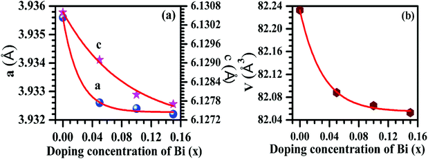 |
| | Fig. 3 Variations of (a) lattice parameters and (b) unit cell volume as a function of different concentrations of Bi3+ ions (i.e. 0, 5, 10 and 15 mol%). The circular, stars and hexagon points show the refined values obtained after Rietveld refinement and the continuous lines indicate an exponentially fitted curve. | |
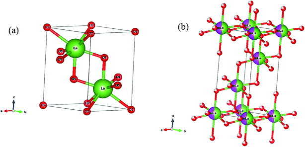 |
| | Fig. 4 Ball and Stick model of the unit cells of space groups (a) Pm1 and (b) Rm. | |
 |
| | Fig. 5 (a) A Williamson–Hall plot of the Er3+/Yb3+ co-doped La2O3 nano-phosphor sample and (b) a variation in lattice strain as a function of different concentrations of Bi3+ ions (i.e. 0, 5, 10 and 15 mol%). | |
The detailed information of the estimated values for the crystallite size and the lattice strain are tabulated in Table 2.
Table 2 Crystallite size and lattice strain obtained from Williamson–Hall method of the Er3+/Yb3+/xBi3+ tri-doped La2O3 nano-phosphors (i.e. x = 0, 5, 10 and 15 mol%)
| Concentration of Bi3+ (x mol%) |
Phase 1 (Pm1) |
Phase 2 (Rm) |
| d (nm) |
ε |
d (nm) |
ε |
| 0 |
55.9 |
5.3 × 10⁻⁴ |
|
|
| 5 |
65.1 |
1.5 × 10⁻³ |
|
|
| 10 |
66.3 |
1.6 × 10⁻³ |
69.3 |
6.9 × 10⁻⁴ |
| 15 |
88.9 |
2.2 × 10⁻³ |
73.7 |
8.4 × 10⁻³ |
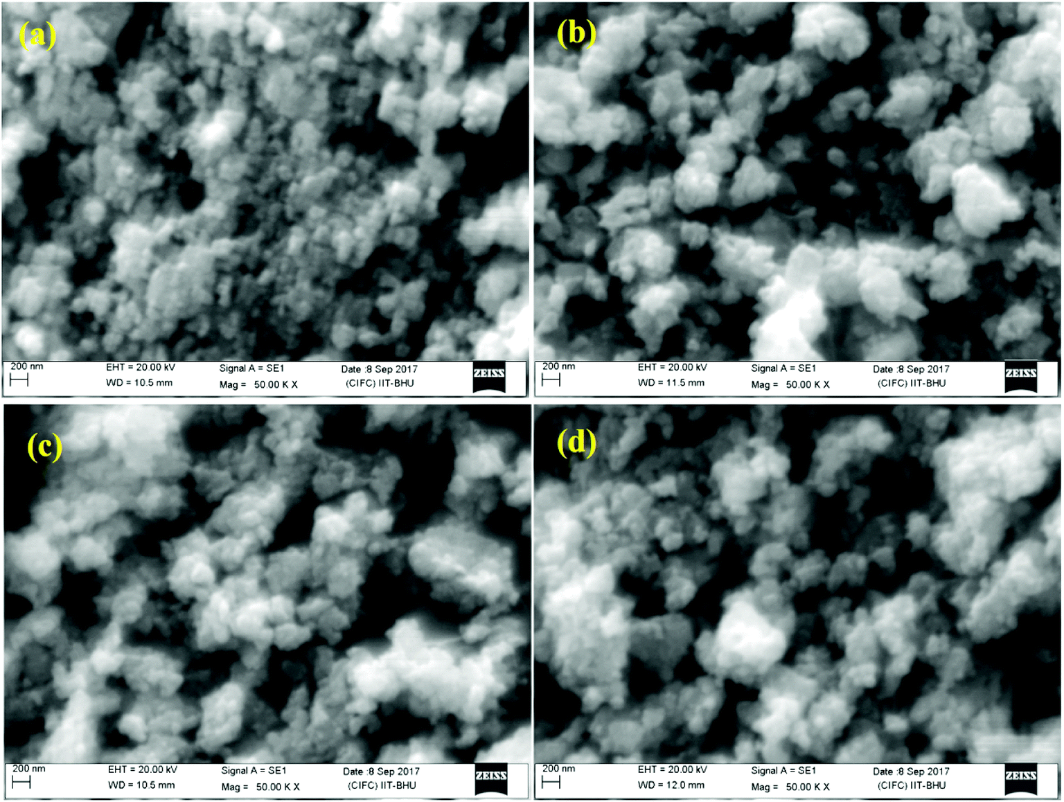
3.1.2 SEM and EDS measurements. Fig. 6 shows scanning electron microscopy (SEM) micrographs for different concentrations of Bi3+ ions (i.e. x = 0, 5, 10, and 15 mol%) in the Er3+/Yb3+/xBi3+ tri-doped La2O3 nano-phosphor samples. The average particles size for all the samples were estimated considering large number of particles using ImageJ software. Its average values are found to be 101, 113, 118 and 141 nm for x = 0, 5, 10 and 15 mol% concentrations of Bi3+ ions in the Er3+/Yb3+/xBi3+ tri-doped La2O3 phosphors, respectively. The particles of the phosphor are almost spherical in shape and agglomerated to each other in different orientations. It is also clear from Fig. 6(a–d) that the particles size of the phosphor increases on addition of Bi3+ ions.15,27
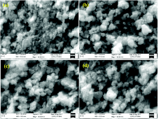 |
| | Fig. 6 SEM micrographs of the Er3+/Yb3+/xBi3+ tri-doped nano-phosphor samples with x = (a) 0 mol%, (b) 5 mol%, (c) 10 mol% and (d) 15 mol% concentrations of Bi3+ ions. | |
Fig. 7 shows the energy dispersive spectroscopic (EDS) patterns of the Er3+/Yb3+/xBi3+ tri-doped La2O3 nano-phosphor samples for different concentrations of Bi3+ ions (i.e. 0, 5, 10 and 15 mol%). Since, the EDS technique used in conjunction with SEM for elemental analysis is not much suitable for lighter elements like oxygen; hence, we report only their qualitative analysis rather than quantitative. The EDS spectra reveal the presence of La, Er, Yb, Bi and O elements in the tri-doped nano-phosphor samples.15 As is clear from Fig. 7(a) that the Er3+/Yb3+ co-doped La2O3 nano-phosphor contains only La, Yb, Er and O elements in the sample. When the Bi3+ ion is added in the co-doped phosphor it contains an additional Bi element along with La, Er, Yb and O elements (see Fig. 7(b–d)).
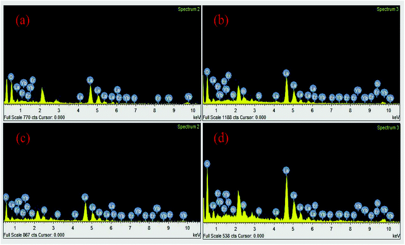 |
| | Fig. 7 The EDS spectra of the Er3+/Yb3+/xBi3+ tri-doped samples with x = (a) 0 mol% (b) 5 mol% (c) 10 mol% and (d) 15 mol% concentrations of Bi3+ ions. | |
3.2 Optical characterization
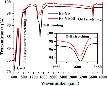
3.2.1 FTIR measurements. The FTIR spectra of the Er3+/Yb3+/xBi3+ tri-doped La2O3 phosphor samples were recorded in the range of 400–4000 cm−1 for x = 0 and 5 mol% concentrations of Bi3+ ions and the spectra thus obtained are shown in Fig. 8. The spectra show peaks centred at 411, 490 and 638 cm−1 in the 400–650 cm−1 region and they are assigned to be stretching vibrations of La–O molecule, respectively.8,15 The spectra also contain a peak at 855 cm−1 due to asymmetric stretching vibration of the C–O molecule. Since the samples have been synthesized through solution combustion method, the spectra contain two peaks due to hydroxyl group at 1462 and 3615 cm−1 corresponding to the bending and stretching vibrations of H2O content, respectively. The presence of O–H group has been also verified from the XRD patterns in the form of La(OH)3. The La(OH)3 phase is present in a very small amount and can decrease the emission intensity.8 The inset figure shows the zoomed part of the stretching vibration of O–H molecule for the lattice vibration of 3615 cm−1. It is also clear from the figure that the intensity of O–H bands decreases considerably in presence of Bi3+ ions. This supports the fact that on increasing the doping concentrations of Bi3+ ions the emission intensity arising from the thermally coupled levels of Er3+ ion could be increased.
 |
| | Fig. 8 FTIR spectra of the Er3+/Yb3+/xBi3+ tri-doped La2O3 nano-phosphors for different concentrations of Bi3+ ions (i.e. x = 0 and 5 mol%). The inset figure shows the zoomed part (3550–3650 cm−1) of stretching vibration of the O–H molecule. | |
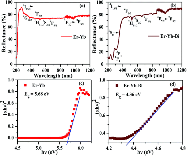
3.2.2 Absorption measurements and optical band gap calculation. The UV-Vis-NIR absorption spectra of the Er3+/Yb3+/xBi3+ tri-doped La2O3 phosphor samples monitored in the 200–1200 nm region for x = 0 and 5 mol% concentrations of Bi3+ ions are shown in Fig. 9(a and b). The spectra contain various absorption bands due to Er3+, Yb3+ and Bi3+ ions. Fig. 9(a) shows large number of peaks at 381, 490, 523, 548 and 671 nm and they are attributed to 2I15/2 → 4G11/2, 4F5/2, 2H11/2, 4S3/2 and 4F9/2 transitions of Er3+ ion, respectively.12–18 The figure also shows a broad band centered at 976 nm due to 2F7/2 → 2F5/2 transition of Yb3+ ion.15 When the Bi3+ ion is added in the phosphor the spectrum contains additional bands in the 220–340 nm region due to Bi3+ ion (see Fig. 9(b)). The bands seen at 253 and 310 nm are due to 1S0 → 1P1 and 1S0 → 3P1 transitions of the Bi3+ ion, respectively.15 It is also clear from Fig. 9(a and b) that there is no absorption band due to the host. The broad band observed in the NIR region proves the larger absorption cross section of Yb3+ ion for NIR light (i.e. 976 nm). This could be favorable for larger emission intensity.
 |
| | Fig. 9 The absorption spectra (a and b) and the optical band gaps (c and d) of the Er3+/Yb3+/xBi3+ tri-doped La2O3 nano-phosphors (i.e. x = 0 and 5 mol%). | |
The optical band gap has been calculated for the La2O3 phosphors in both the cases using Wood and Tauc formula:35
where
Eg,
hυ and
B are the band gap energy, the incident photon energy and band tailoring constant, respectively. The value of ‘
m’ has been used as (1/2) for direct band gap allowed transition.
10,15 The (
αhυ)
2 versus hυ curves have been plotted in both the cases and the obtained curves are shown in
Fig. 9(c and d). The optical band gap is calculated as 5.68 eV in the pure La
2O
3 phosphor (see
Fig. 9(c)) and matches to the reported value 5.80 eV.
15 The value of optical band gap is reduced considerably in presence of Bi
3+ ions and it is 4.36 eV (see
Fig. 9(d)). It has been also reported that the optical band gap of the material was decreased in presence of Bi
3+ ion.
36,37 The Bi
3+ ion creates some energy levels as a continuous band with the 6s
2 valance electrons. We have also observed similar effect of Bi
3+ doping on the optical band gap of the phosphor materials.
15,38 It is also clear from the
Fig. 9(c and d) that the optical band gap greatly depends on the concentrations of Bi
3+ ions. The decrease in optical band gap may promote large number of the excited ions in the upper energy levels. As a result, one can achieve large emission intensity in presence of Bi
3+ ions.
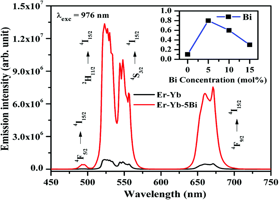
3.2.3 Upconversion measurements. The upconverted emission spectra of the Er3+/Yb3+/xBi3+ tri-doped La2O3 nano-phosphor samples (where x = 0, 5, 10, and 15 mol%) have been recorded in the spectral range of 450–750 nm using 976 nm excitation source and the spectra thus obtained are shown in Fig. 10. The phosphor sample gives a weak blue (at 492 nm), strong green (at 523 and 548 nm) and red (at 660 and 671 nm) upconversion emissions due to 4F5/2 → 4I15/2, 2H11/2 → 4I15/2, 4S3/2 → 4I15/2, and 4F9/2 → 4I15/2 transitions of Er3+ ion, respectively.12–18 The blue emission arises due to absorption of three 976 nm photons whereas the green and red emissions have been observed due to absorption of two 976 nm photons, respectively.15 The emission intensity of the phosphors has been measured for different concentrations of Bi3+ ions while the concentrations of Er3+ and Yb3+ ions are fixed at 0.7 and 3.0 mol%, respectively. It has been observed that the emission intensity of Er3+ ion initially increases on increasing the concentrations of Bi3+ ions upto 5 mol%. After this, the emission intensity of the sample decreases due to concentration quenching. This is due to the fact that at higher concentrations, the distance between the ions becomes smaller compared to their critical distance and the excitation energy migrates to the quenching sites.10,15 The effect of Bi3+ ion concentration on the emission intensity of the Er3+/Yb3+ co-doped La2O3 phosphors is shown as inset in Fig. 10. The figure shows that the emission intensity is found to be optimum for 5 mol% concentrations of Bi3+ ions. The figure also shows that the emission intensity of the co-doped phosphor is enhanced upto 15 times in presence of Bi3+ ions.
 |
| | Fig. 10 The upconverted emission spectra of the Er3+/Yb3+/xBi3+ tri-doped La2O3 nano-phosphors (where x = 0 and 5 mol%) on excitation with 976 nm. The inset figure shows the effect of Bi3+ ion concentration on the emission intensity of the Er3+/Yb3+ co-doped La2O3 nano-phosphor samples. | |
There may be several reasons for an increase in the emission intensity of Er3+ ion in the phosphor sample. The initial reason is that when the Bi3+ ion is co-doped in the phosphor; the crystallite size of the phosphor increases from 55.9 to 65.1 nm. This improves the crystallinity of the phosphor sample. The effect of Bi3+ ion concentration on the crystallinity of the phosphor has been studied by Choudhary et al. and they have found an enhancement in the emission intensity of the dopant ions due to improvement in crystallinity.27 It has been also mentioned in the XRD section that the phase of the phosphor remains the same on co-doping of 5 mol% concentrations of Bi3+ ions and we have also found optimum emission intensity in this case.15 When the concentrations of Bi3+ ion is increased further from 10 to 15 mol% a small amount of an additional rhombohedral phase of BiLa2O4.5+δ was observed in the phosphor sample. The presence of an additional phase creates large strain in the phosphor and reduces the emission intensity significantly for higher concentrations of Bi3+ ions. The other possibility is due to an increase in the particles size of the phosphor via Bi3+ doping. As has been observed in the SEM micrographs that the particles size of the phosphor increases as the concentration of Bi3+ ions is increased.15,27 The FTIR analysis also shows a reduction in the intensity of O–H bands significantly in presence of Bi3+ ion. It has been also reported that the presence of Bi3+ ion increases the lifetime of the emitting levels, which supports the larger photoluminescence intensity for the phosphor samples.15,38 The optical band gap analysis also shows a reduction in the optical band gap from 5.68 to 4.36 eV in presence of Bi3+ ion. This leads to promote large number of excited ions in the upper energy levels, thereby emitting large photoluminescence intensity. Thus, in our case we could observe an enhancement in the emission intensity upto 15 times in presence of Bi3+ ion due to these combined effects.
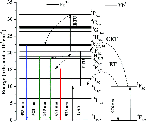
The excitation and emission processes involved in Er3+ and Yb3+ ions and energy transfer between them are shown in Fig. 11. The figure shows that the ground state absorption (GSA), energy transfer upconversion (ETU) and cooperative energy transfer (CET) processes are observed effectively. As the Er3+, Yb3+ co-doped La2O3 sample is excited by 976 nm the Yb3+ ions are promoted from their ground state (2F7/2) to the excited state (2F5/2) due to large absorption cross section for this wavelength. The excited Yb3+ ions transfer their excitation energy in the ground state (4I15/2) of Er3+ ions on relaxation. Due to this, the Er3+ ions are excited to 4I11/2 state. The Er3+ ions are also excited directly to 4I11/2 state weakly through GSA due to absorption of 976 nm photons. These ions are further excited to 4F7/2 state due to absorption of another photon through ETU process. On the other hand, the two Yb3+ ions transfer their energy simultaneously to Er3+ ions in the ground state (4I15/2) due to CET, which promote the Er3+ ions to 4F7/2 state also. This facilitates large number of the excited ions in 4F7/2 state and some of the ions are further promoted to 2P3/2 state through ETU process. Finally, the 4F5/2, 2H11/2, 4S3/2 and 4F9/2 states are populated, which give radiative transitions at 493, 523, 548 and 671 nm wavelengths, respectively.12–18,20
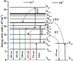 |
| | Fig. 11 Energy level diagrams of the Er3+ and Yb3+ ions and the excitation and emission processes in them. | |
3.2.4 Induced optical heating measurements. The induced optical heating in the Er3+/Yb3+ co-doped phosphors have been widely studied by different groups of researchers in different host materials.4–6,19 They have measured the emission intensity of the thermally coupled levels (2H11/2 and 4S3/2) of the Er3+ ion at various pump powers and observed a change in emission intensities of the two bands arising from them to a common lower level. We have monitored the emission intensities for the two emission bands of Er3+ ion in the Er3+/Yb3+/5Bi3+ tri-doped La2O3 phosphor at various pump powers of 976 nm excitation and they are shown in Fig. 12. As is clear from Fig. 12 that the intensity of band lying at lower wavelength (λ) side is smaller than that of at higher (λ) side. As the pump power is increased, the excited ions are promoted from the 4S3/2 level to the 2H11/2 level due to heating effect. Therefore, the intensity of band in lower (λ) side increases and very soon its intensity becomes larger than the other bands. The fluorescence intensity ratio (FIR) of the two bands increases with pump power. The heating arises due to an increase in pump power. Addition of surface modifiers can also affect the FIR due to increase in emission intensities of the thermally coupled peaks.24–27
 |
| | Fig. 12 Effect of incident pump powers on the upconverted emission intensity of the thermally coupled levels (2H11/2 and 4S3/2) of the Er3+ ion in the Er3+/Yb3+/5Bi3+ tri-doped La2O3 nano-phosphor (a–c) and (d) FIR of the Er3+/Yb3+/xBi3+ tri-doped La2O3 nano-phosphors (i.e. x = 0 and 5 mol%) on excitation with 976 nm. | |
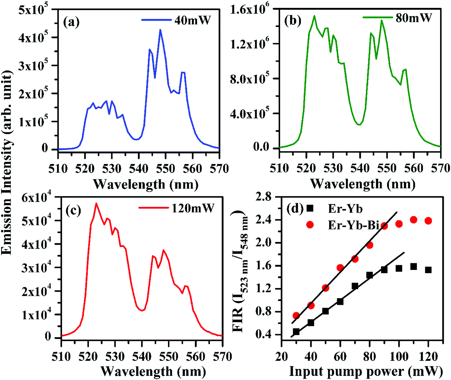
It is clear from the figure that the emission intensity of the 523 nm band due to 2H11/2 → 4I15/2 transition is smaller than that of 548 nm band due to 4S3/2 → 4I15/2 transition, respectively at 40 mW pump power. It shows that initially, the population of the ions in the excited 2H11/2 level is smaller than that of 4S3/2 level at lower pump power. It also shows that the phosphor sample emits very intense green photoluminescence even at very low pump power (see Fig. 12(a)). As the pump power is increased the excited ions are promoted from 4S3/2 level to 2H11/2 level. As a result, the emission intensity of the peak arising from 2H11/2 level increases considerably relative to the intensity of the peak arising from 4S3/2 level and reaches to almost in equal values at 80 mW pump power (see Fig. 12(b)). When the pump power was increased further from 80 to 120 mW the overall intensity of both the emission bands is reduced due to the sample heating. However, the emission intensity of the peak arising from the 2H11/2 thermally coupled level is increased while the emission intensity of the peak arising from the 4S3/2 thermally coupled level is found to decrease. Fig. 12(c) shows that the emission intensity of the peak arising from 2H11/2 level (523 nm) is larger than that of 4S3/2 level (548 nm) at 120 mW pump power. The variation in emission intensities has been used to calculate the fluorescence intensity ratio (i.e. FIR = I523 nm/I548 nm) in absence and presence of 5 mol% Bi3+ ions (see Fig. 12(d)). The FIR versus input pump power plot shows almost linear behavior upto 90 mW in both the cases. However, the plots show a deviation from linear behavior for higher pump powers i.e. greater than 90 mW. This occurs due to optical heating in the sample at higher pump powers. The FIR of the phosphor is found to be sustaining higher values of pump power in presence of Bi3+ ions. Thus, the tri-doped phosphor may provide a platform for the study of optical heating based applications.
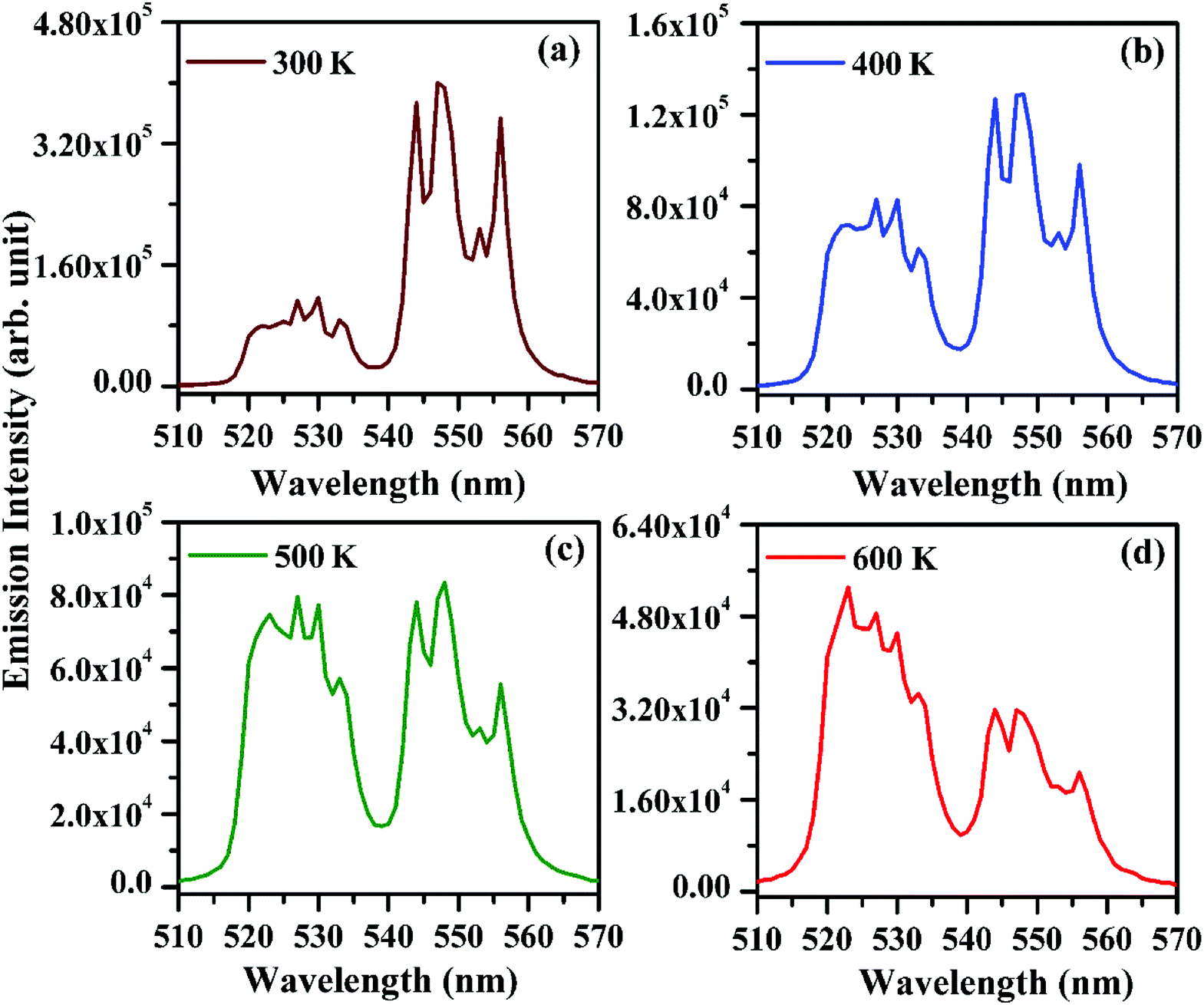
3.2.5 Temperature sensing measurements of the nano-phosphor. As has been observed earlier, the emission intensity of the bands arising from the thermally coupled levels (2H11/2 and 4S3/2) of the Er3+ ion varies significantly on increasing the pump power. The increase in pump power heats the sample due to non-radiative relaxations and thereby affects the intensity of the bands arising from the two levels. We have measured the emission intensity of the peaks arising from the thermally coupled levels by heating the Er3+/Yb3+/xBi3+ tri-doped La2O3 phosphor samples (i.e. x = 0 and 5 mol%) externally in the range of 300–625 K on excitation with 976 nm at 40 mW. The effect of temperature on the emission intensities of the thermally coupled levels of Er3+ ion in the Er3+/Yb3+/5Bi3+ tri-doped La2O3 phosphor on excitation with 976 nm at 40 mW is shown in Fig. 13. The emission intensity of the bands arising from the thermally coupled levels (i.e. 2H11/2 and 4S3/2) of the Er3+ ion at 523 and 548 nm wavelengths differs from each other at room temperature.4–6,24–27 Initially, the emission intensity of 523 nm band is less than that of 548 nm band at 300 K (see Fig. 13(a)). Fig. 13(b) shows significant increase in the emission intensity of 523 nm band at 400 K. However, at 500 K the emission intensities of the two bands are found almost the same (see Fig. 13(c)). As temperature of the phosphor sample further increases, the overall emission intensity of the 523 and 548 nm emission bands decreases due to thermal quenching. Actually, the increase in temperature of the sample leads to increase the lattice vibrations of the ions and thereby non-radiative transitions, which decreases the emission intensity. The relative intensity of the two emission bands changes accordingly and the emission intensity of the 523 nm band is larger compared to that of 548 nm band at 600 K (see Fig. 13(d)). The variation in emission intensity is due to transfer of the excited ions from the lower to the upper thermally coupled levels via the lattice vibrations. This increases the population of ions in the upper component of the thermally coupled level and enhances the emission intensity of 523 nm band. The similar observation has been made by Dey et al. in the Er3+/Yb3+ co-doped phosphor.11 The figures clearly show that there is a variation in emission intensities of the two bands arising from the thermally coupled levels of the Er3+ ion.
 |
| | Fig. 13 Effect of temperature on emission intensities of the thermally coupled levels (i.e. 523 and 548 nm emission bands) of the Er3+/Yb3+/5Bi3+ tri-doped La2O3 nano-phosphor upon 976 nm excitation excited at 40 mW. | |
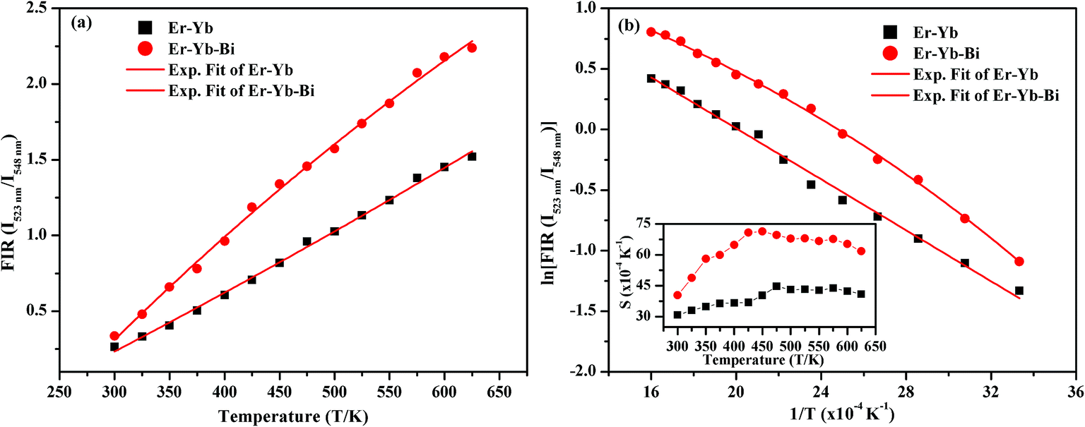
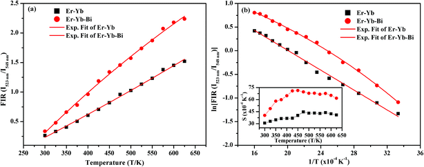
The FIR values have been evaluated using the values of emission intensities of 523 and 548 nm bands as a function of temperature and the plot thus obtained between FIR and the temperature is shown in Fig. 14(a). It has been reported by Pérez-Rodríguez et al.39 that the non-radiative relaxations of the ions arising between the two levels conserve them thermally coupled. The theoretically calculated energy gap value is ∼800 cm−1 and population of the ions in the thermally coupled levels seems to follow Boltzmann population distribution law.11 The fluorescence intensity ratio (FIR) of the two thermally coupled 2H11/2 and 4S3/2 levels of the Er3+ ion is related by the following relation:
| | |
FIR = I523 nm/I548 nm = Rexp(−ΔE/kT)
| (i) |
where
I523 nm and
I548 nm are the emission intensities of the thermally coupled
2H
11/2 and
4S
3/2 levels, respectively. The
R and Δ
E are the proportionality constant and energy gap between the two sublevels, respectively. The
k and
T are Boltzmann's constant and absolute temperature of the phosphor sample, respectively.
4–6
 |
| | Fig. 14 (a) Plots of FIR(I523 nm/I548 nm) versus temperature, (b) ln(FIR(I523 nm/I548 nm)) versus T−1 and inset in (b) shows sensitivity versus temperature for the Er3+/Yb3+/xBi3+ tri-doped La2O3 nano-phosphors on excitation with 976 nm laser at 40 mW (i.e. x = 0 and 5 mol%). | |
It is also clear from the Fig. 14(a) that the FIR of the thermally coupled 2H11/2 and 4S3/2 levels increases non-linearly for the Er3+/Yb3+/xBi3+ tri-doped La2O3 phosphor samples (i.e. x = 0 and 5 mol%), respectively as the temperature of the phosphor is increased from 300 to 625 K. The presence of Bi3+ ion in the co-doped phosphor gives the larger FIR with the increase in temperature. We have also plotted a graph between the logarithmic of FIR and the inverse of temperature (i.e. T−1) and it is shown in Fig. 14(b). The ln(FIR) versus T−1 plots were fitted in eqn (i), which give the slope values as 1051 and 1077 for the co-doped and tri-doped phosphors, respectively. We have calculated the energy separation between the two thermally coupled levels using these values and they are found to be 730 and 749 cm−1 for the co-doped and tri-doped phosphor samples, respectively. The calculated values thus obtained in our case are very close to the earlier reported value (i.e. 738.54 cm−1).26
The temperature sensitivity of the phosphor sample is an important term for highly sensitive optical temperature sensors. The sensitivity (S) is obtained through a variation of FIR with the increase in temperature of the phosphor sample and it can be calculated using the following expression:24–27
| | |
S = d(FIR)/dT = FIR(ΔE/kT2)
| (ii) |
where the terms have their usual meanings.
The plots between the sensitivity and the temperature were obtained using relation (ii) for the measured range of temperatures i.e. 300–625 K in absence and presence of Bi3+ ions and it is shown as inset in Fig. 14(b). The inset of Fig. 14(b) shows that the sensitivity varies as the temperature of the phosphor is increased. The relative sensitivity of the Er3+/Yb3+ co-doped phosphor sample varies from 31 × 10−4 K−1 to 41 × 10−4 K−1 on increasing the temperature from 300 to 625 K, respectively and the maximum relative sensitivity is found to be 45 × 10−4 K−1 at 475 K. Similarly, the relative sensitivity of the Er3+/Yb3+/Bi3+ tri-doped phosphor sample initially increases with the increase in temperature and then it is found to decrease after reaching to its maximum value as 71 × 10−4 K−1 at 450 K.24 The presence of Bi3+ ion also improves the temperature sensitivity of the Er3+/Yb3+ co-doped La2O3 phosphor significantly, which is due to improvement in the local crystal structure around the ions. The sensitivity observed in our case has been compared with the earlier reported values in different host materials and they are given in Table 3.24,40–44 The table shows that the value of sensitivity observed in our case is found to be larger than the earlier reported values in different host materials. Therefore, the Er3+/Yb3+/Bi3+ tri-doped La2O3 nano-phosphor may be used in the temperature sensing applications.
Table 3 The temperature sensitivity observed in different Er3+/Yb3+ activated host materials
| Materials |
Temperature range |
Sensitivity (S) |
Ref. |
| Er3+, Yb3+ co-doped Gd2O3 |
300–900 K |
39 × 10−4 K−1 at 300 K |
40 |
| Er3+, Yb3+ co-doped Y2SiO5 |
300–600 K |
56 × 10−4 K−1 at 400 K |
41 |
| Er3+, Yb3+ co-doped NaYF4 |
273–333 K |
42 × 10−4 K−1 at 328 K |
42 |
| Er3+, Yb3+, Li+ tri-doped Na2Zn2PO4 |
300–603 K |
65 × 10−4 K−1 at 603 K |
43 |
| Er3+, Yb3+ co-doped La2O3 |
300–625 K |
45 × 10−4 K−1 at 475 K |
Present work |
| Er3+, Yb3+, Bi3+ tri-doped La2O3 |
300–625 K |
71 × 10−4 K−1 at 450 K |
Present work |
| Er3+, Yb3+, Li+ tri-doped Y2Ti2O7 |
298–673 K |
67 × 10−4 K−1 at 363 K |
24 |
| Er3+, Yb3+ co-doped NaLnTiO4 |
300–510 K |
45 × 10−4 K−1 at 573 K |
44 |
4. Conclusions
The Er3+/Yb3+/Bi3+ tri-doped La2O3 nano-phosphor has been synthesized through solution combustion method. The structural measurements of the phosphor show an improvement in the local crystal structure in presence of Bi3+ ions. The lattice parameters and the particles size of the phosphor increase on increasing the Bi3+ concentrations. The Er3+/Yb3+ co-doped phosphor emits a weak blue, strong green and red upconverted emission bands upon 976 nm excitation. The emission intensity of the co-doped phosphor sample is enhanced upto 15 times in presence of Bi3+ ion due to combined effect of an increase in crystallinity, particles size and reduction in optical quenching centers. The fluorescence intensity ratio (FIR) of the thermally coupled levels shows an efficient induced optical heating in the phosphor. The FIR of the 523 and 548 nm emission bands also varies with the increase in temperature of the phosphor. The relative temperature sensing sensitivity is calculated to be 71 × 10−4 K−1 at 450 K. Thus, the Er3+/Yb3+/Bi3+ tri-doped La2O3 nano-phosphor may be suitable candidate for the photonic devices, as an optical heater and temperature sensor.
Conflicts of interest
The authors declare that there is no conflict of interest in the manuscript.
References
- E. Downing, L. Hesselink, J. Ralston and R. Macfarlane, Science, 1996, 273, 1185–1189 CrossRef CAS.
- E. F. Schubert and J. K. Kim, Science, 2005, 308, 1274–1278 CrossRef CAS PubMed.
- R. S. Yadav, R. K. Verma, A. Bahadur and S. B. Rai, Spectrochim. Acta, Part A, 2015, 137, 357–362 CrossRef CAS PubMed.
- P. Du, L. H. Luo and J. S. Yu, Microchim. Acta, 2017, 184, 2661–2669 CrossRef CAS.
- M. Mondal, V. K. Rai and C. Srivastava, Chem. Eng. J., 2017, 327, 838–848 CrossRef CAS.
- P. Du, L. H. Luo, H. K. Park and J. S. Yu, Chem. Eng. J., 2016, 306, 840–848 CrossRef CAS.
- R. H. Horng, C. C. Chiang, H. Y. Hsiao, X. Zheng, D. S. Wu and H. I. Lin, Appl. Phys. Lett., 2008, 93, 111907 CrossRef.
- R. S. Yadav, R. K. Verma, A. Bahadur and S. B. Rai, Spectrochim. Acta, Part A, 2015, 142, 324–330 CrossRef CAS PubMed.
- P. Du, P. Zhang, S. H. Kang and J. S. Yu, Sens. Actuators, B, 2017, 252, 584–591 CrossRef CAS.
- R. S. Yadav, S. J. Dhoble and S. B. Rai, Sens. Actuators, B, 2018, 27, 1425–1434 CrossRef.
- R. Dey and V. K. Rai, Dalton Trans., 2014, 43, 111–118 RSC.
- A. Zhou, F. Song, Y. Han, F. Song, D. Ju, K. Adnan, L. Liu and M. Feng, J. Lumin., 2018, 194, 225–230 CrossRef CAS.
- V. Kumar, S. Som, S. Dutta, S. Das and H. C. Swart, RSC Adv., 2016, 6, 84914–84925 RSC.
- Q. Xiao, Y. Zhang, H. Zhang, G. Dong, J. Han and J. Qiu, Sci. Rep., 2016, 6, 31327 CrossRef CAS PubMed.
- R. S. Yadav, S. J. Dhoble and S. B. Rai, New J. Chem., 2018, 42, 7272–7282 RSC.
- J. H. Zeng, J. Su, Z. H. Li, R. X. Yan and Y. D. Li, Adv. Mater., 2005, 17, 2119–2123 CrossRef CAS.
- I. Etchart, A. Huignard, M. Berard, M. N. Nordin, I. Hernandez, R. J. Curry, W. P. Gillin and A. K. Cheetham, J. Mater. Chem., 2010, 20, 3989–3994 RSC.
- B. Xu, G. Dong, J. Liu, K. Zou and D. Wang, J. Lumin., 2018, 203, 16–25 CrossRef CAS.
- M. Li, Y. Shi, C. Zhao, F. Yang, Q. Li, Xi. Zhang, S. Wu, H. Chen, J. Liu and T. Wei, Dalton Trans., 2018, 47, 11337–11345 RSC.
- R. S. Yadav, R. K. Verma and S. B. Rai, J. Phys. D: Appl. Phys., 2013, 46, 275101 CrossRef.
- J. K. Cao, W. P. Chen, D. K. Xu, F. F. Hu, L. P. Chen and H. Guo, J. Lumin., 2018, 194, 219–224 CrossRef CAS.
- J. K. Cao, F. F. Hu, L. P. Chen, H. Guo, C. K. Duan and M. Yin, J. Am. Ceram. Soc., 2017, 100, 2108–2115 CrossRef CAS.
- J. K. Cao, X. M. Li, Z. X. Wang, Y. L. Wei, L. P. Chen and H. Guo, Sens. Actuators, B, 2016, 224, 507–513 CrossRef CAS.
- B. P. Singh, A. K. Parchur, R. S. Ningthoujam, P. V. Ramakrishna, S. Singh, P. Singh, S. B. Rai and R. Maalej, Phys. Chem. Chem. Phys., 2014, 16, 22665–22676 RSC.
- M. K. Mahata, T. Koppe, T. Mondal, C. Brüsewitz, K. Kumar, V. K. Rai, H. Hofsäss and U. Vetter, Phys. Chem. Chem. Phys., 2015, 17, 20741–20753 RSC.
- V. K. Rai, A. Pandey and R. Dey, J. Appl. Phys., 2013, 113, 083104 CrossRef.
- A. K. Choudhary, A. Dwivedi, A. Bahadur, T. P. Yadav and S. B. Rai, Ceram. Int., 2018, 44, 9633–9642 CrossRef CAS.
- J. Cao, S. Xu, Q. Zhang, Z. Yang and M. Peng, Adv. Opt. Mater., 2018, 1801059, 1–10 Search PubMed.
- J. Han, L. Li, M. Peng, B. Huang, F. Pan, F. Kang, L. Li, J. Wang and B. Lei, Chem. Mater., 2017, 29, 8412–8424 CrossRef CAS.
- J. K. Cao, L. Li, L. Wang, X. Li, Z. Zhang, S. Xu and M. Peng, J. Mater. Chem. C, 2018, 6, 5384–5390 RSC.
- J. R. Carvajal, Physica B Condens. Matter, 1993, 192, 55–69 CrossRef.
- B. Morosin, Acta Crystallogr., Sect. B: Struct. Crystallogr. Cryst. Chem., 1973, 29, 2647–2648 CrossRef CAS.
- M. Wolcyrz, R. Horyn and F. Bourée, J. Phys.: Condens. Matter, 1999, 11, 5757–5765 CrossRef CAS.
- D. Kumar, N. K. Verma, C. B. Singh and A. K. Singh, AIP Conf. Proc., 2018, 1942, 050024-4 Search PubMed.
- D. L. Wood and J. Tauc, Phys. Rev. B, 1972, 5, 3144–3151 CrossRef.
- X. Jing, C. Gibbons, D. Nicholas, J. Silver, A. Vecht and C. S. Frampton, J. Mater. Chem., 1999, 9, 2913–2918 RSC.
- M. Weigel, W. Middel and G. Blasse, J. Mater. Chem., 1995, 5, 981–983 RSC.
- R. S. Yadav and S. B. Rai, J. Alloys Compd., 2017, 700, 228–237 CrossRef CAS.
- C. Pérez-Rodríguez, L. L. Martín, S. F. León-Luis, I. R. Martín, K. K. Kumar and C. K. Jayasankar, Sens. Actuators, B, 2014, 195, 324–331 CrossRef.
- S. K. Singh, K. Kumar and S. B. Rai, Sens. Actuators, A, 2009, 149, 16–20 CrossRef CAS.
- N. Rakov and G. S. Maciel, Sens. Actuators, B, 2012, 164, 96–100 CrossRef CAS.
- D. T. Klier and M. U. Kumke, J. Phys. Chem. C, 2015, 119, 3363–3373 CrossRef CAS.
- L. Mukhopadhyay, V. K. Rai, R. Bokolia and K. Sreenivas, J. Lumin., 2017, 187, 368–377 CrossRef CAS.
- D. He, C. Guo, S. Jiang, N. Zhang, C. Duan, M. Yin and T. Li, RSC Adv., 2015, 5, 1385–1390 RSC.
|
| This journal is © The Royal Society of Chemistry 2018 |
Click here to see how this site uses Cookies. View our privacy policy here. 
 Open Access Article
 This Open Access Article is licensed under a
  b,
A. K. Singh*b,
Ekta Raia and
S. B. Rai
b,
A. K. Singh*b,
Ekta Raia and
S. B. Rai