 Open Access Article
Experimental study of dust deposition in dynamic granular filters
Wenning Zhou ab,
Juan Maa,
Guoliang Zenga and
Baiqian Liu
 *ab
*ab
aSchool of Energy and Environmental Engineering, University of Science and Technology Beijing, Beijing 100083, China
bBeijing Key Laboratory of Energy Saving and Emission Reduction for Metallurgical Industry, University of Science and Technology Beijing, Beijing 100083, China. E-mail: liubq@ustb.edu.cn; Tel: +86 10 62334891
First published on 19th November 2018
Abstract
The aim of the present study is to investigate the process of dust deposition and its effects on the filtration performance of dynamic granular filters. We proposed a new theoretical explanation about the model for dust cake formation and growth, especially for the compression model at higher filtration superficial velocities in dynamic granular filters. The thickness and porosity of dust cakes can be estimated by formulas. Then, the effects of cake formation and growth on filtration performance were examined. It is found that there is an optimum thickness of the cake at which the dynamic granular filter achieves excellent collection efficiency with low system resistance. Moreover, an increasing pattern of pressure drop with cake thickness under different filtration superficial velocities was observed. Experimental results show that the pressure drops across the filter system and dust cake increase exponentially with increasing filtration superficial velocity. An appropriate filtration superficial velocity should be considered to achieve optimum filtration performance in dynamic granular filters. It is expected that the results of this study could provide useful information on designing dynamic granular filters for removal of dust particulates in Integrated Gasification Combined-Cycle (IGCC) and Pressurized Fluidized-Bed Combustion (PFBC).
Introduction
In recent years, there has been increasing concern about air pollution created by fast industrial growth, which has made it absolutely crucial to develop techniques and equipment for purification of industrial gas.1 The gas purification system of clean coal technology has been proposed as the most attractive technology for fine particle (PM2.5) collection and dust removal at high temperature conditions, which can be applied to gas turbines in advanced coal-based power generation systems such as Integrated Gasification Combined-Cycle (IGCC) and Pressurized Fluidized-Bed Combustion (PFBC). Therefore, effective methods of eliminating particulate material from advanced coal-based power generation systems, i.e., hot gas clean-up, are of great importance.2Traditional gas–solid separation equipment mainly includes a fabric filter, cyclone cleaner, electrostatic precipitator (ESP) and wet dust collector.3 However, except for cyclone cleaner, most of these are difficult to be applied in hot gas purification. The fine dust separation efficiency of the cyclone is limited due to the structure and the mechanism of gravitational settling.4 For fabric filters, the separation efficiency is limited by temperature and high resistance.5 The ESP has the critical problem of large amount of maintenance work.6 As for wet dust collectors, they are usually vulnerable to corrosion and production of waste liquids and solids, causing secondary pollution.7
The key components for gas–solid separation equipment are dust removal devices, especially for hot gas clean-up, which should be filtrated with efficiency, reliability, low resistance and low cost. Granular filters have a long history in separation technology, regarded as having the most potential in industrial use of granular material to separate particles from flue gas.8–11 As granular material consists of inorganics such as silica sand, ceramics and the particles are made by refractories, granular filters can be adopted in hot gas cleaning such as IGCC and PFBC.12 So far, granular filters operating in fixed bed conditions have been applied in small industrial devices. However, the moving granular filter still remains in research labs and has not been widely applied in industry.
Zhang et al.13 conducted lab-scale coal pyrolysis experiments on a moving granular filter. They claimed that a higher filter height, slower superficial gas velocity and smaller medium size are favourable to decrease the dust content in the pyrolysis volatiles of coal. Previous experiments have indicated that the collected dust particles accumulate on the free surface of granules and form a compact structure during the deep-bed filtration mode, which has a strong ability to trap fly ash, so that collection efficiency can be improved.14 Hence, the structure of the granular bed and dust cake formation and growth play important roles in the filtration performances of granular beds. Much research work has been done in this area on granular filters, including that by Rodon and Lee,15 Otoom,16 Chen and Hsiau,17 Qin and Pletcher,18 etc. Various filter structures and flow patterns of granular material have been proposed. Meanwhile, several researchers have reported their investigations on pressure drop, collection efficiency and porosity of dust cake during cake filtration in granular filters.19–21 The effects of dust properties, granular material properties, and structures of the filter on dust cake formation and collection efficiency of the filter have been examined. Choi22 concluded that the dust cake was compressed by former cake layers with drag forces of later-formed dust layers, which was based on the dust build up model proposed by Schmidt.23 Moreover, Qin and Pletcher18 proposed that two increasing patterns of pressure drop were caused by different deposit distributions, termed homogeneous and heterogeneous depositions, rather than different increasing mechanisms of pressure drop. Although much work has been carried out in this field, in-depth understanding of the mechanism of cake formation/growth and design principles of granular filters is still missing, which is essential to the collection efficiency, filter system resistance and further industrialization of moving granular filters. In our previous study, we proposed a novel design of moving granular filter, i.e., dynamic granular filter.24 Inspired by dam technique in irrigation works, the novel dynamic granular filter was designed with louvers and sublouvers as dams and downflow weirs, respectively. We proposed using the inertial number criterion, which guarantees that the granular materials are kept in dynamic condition, to design the structure and effectively reduce the stagnant zone of the dynamic granular filter. There are two types of structure for dynamic granular filters, vertical and inclined filters. In the present study, the experiments were conducted on an inclined filter.
As is known, the dust cake grows thicker with filtration time and the pressure drop across the cake increases. The deposition of dust cake greatly affects the performance of granular filter performance, as well as collection efficiency and energy consumption. Based on the newly designed dynamic granular filter, this study focused on the formation and growth of dust cake during filtration. A new theoretical explanation regarding the model of cake formation and growth was proposed. In addition, the effects of filtration superficial velocity on cake formation and growth and also the pressure drop of granular filter system were examined. It is hoped that this study could lay a foundation for the industrialization of this promising dust removal technology.
Experimental section
Mechanism of dynamic granular filter
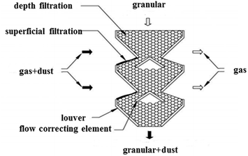
In our previous study, a dynamic granular filter was proposed with the louver and sub-louver structure, which can form a layer of fast granular particle flow and reduce the stagnant zone. Therefore, the granular flow layer can deliver the dust cake on the gas–solid separation surface and the cake will not grow too strong.24 The schematic diagram of vertical dynamic granular filter is shown in Fig. 1. There are a few factors affecting collection efficiency such as the physical properties of the filter material (filter material size, surface roughness, etc.), dust physical properties, gas flow field and other factors. In principle, several separate mechanisms could contribute to the filtration efficiency, including inertial impaction, diffusion, gravitational settling, interception, and electrostatic attraction.25,26 In dynamic granular filters, the dust particulates follow the curvilinear path of gas motion and tend to move along the gas streamlines until being deposited on the filter granules. The collection mechanisms mainly include inertial impaction and diffusion.27The following analyses are carried out for a case where the mechanisms of inertial impaction and diffusion dominate the filtration performance. For the inertial impaction filters, the Stokes number St is defined as28,29
 | (1) |
 | (2) |
Experimental apparatus and procedures
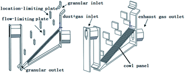
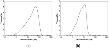
When the dust laden gas reaches the surface of the granular layer, the dust particulates are intercepted, captured, and deposited on the surface of the filter granules to form a dust cake. Different from a normal granular filter, the dynamic granular filter was designed with the structure of retaining dam and overflow dam. The function of the retaining dam is to ensure that the filter granules fall without forming a particle stack induced by gravity and the aim of the overflow dam is to interrupt the force chain. Thus, the stagnant zone becomes active and the fast-moving granular layer delivers the collected dust particulates out of the filter. With the increase in the thickness of dust cake, the porosity of the cake decreases and the pressure drop of the filter system increases rapidly.Fig. 2 illustrates the structure of the inclined dynamic granular filter used in the current experiments. All of the experiments of the present study are cold tests. Mung beans with particle sizes ranging from 3 mm to 5 mm and a density of 1300 kg m−3 were used as the filter granules. The dust particulates applied in the experiments were obtained from a 150 MW circulating fluidized bed boiler. Fig. 3 shows the size distribution of dust particulates measured by Malvern Particle Size Analyzer. It can be seen from the figure that the peak is about 45.6 μm at the dust laden gas inlet and 12.7 μm at the outlet. It is evident that the dynamic granular filter has an excellent performance of trapping dust particulates. There are three pressure measuring points in each layer of the granular material, and the average value is taken as the filter system pressure drop. Main parameters and data used in the experiments are shown in Table 1.
 | ||
| Fig. 3 Size distribution of dust particles at the (a) inlet and (b) outlet of experimental apparatus. | ||
| Parameter | Data |
|---|---|
| Density of dust particle (kg m−3) | 1550 |
| Filtration superficial velocity (m s−1) | 0.5, 0.6, 0.7 |
| Flow rate of granular (g min−1) | 300 |
| Effective dust removal area on free surface (m2) | 0.292 |
| Values of air flow (m3 min−1) | 18 |
| Gas viscosity (Pa s) | 1.849 × 10⁻⁵ |
| Concentration of dust particle (g m−3) | 2 |
| Diameter of granules (μm) | 35 |
The experiments are divided into three stages. First, we carry out tests on pressure drop of the filter granules under different superficial filtration velocities at free load condition, i.e. without adding dust particulates into gas flow. The second stage operates at the fixed bed condition. The dust particulates are fed into gas flow by a screw feeder and an air fan. The filter granules are kept static to form a dust cake. The pressure drop of the filter starts to increase. After a certain period of time, the increase rate of pressure drop becomes smaller. The feeder for granules will be then opened and the fixed bed transfers to dynamic granular bed at the final stage. The dust particulates deposited on the cake are updated and delivered out of the filter. The cake thickness could be adjusted by the flow rate of filter material. The detailed diagram for the filter system can be found in our previous study.24
Results and discussion
The three stages of filtering process and cake growth
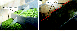
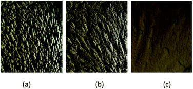
The process of filtering in dynamic granular bed also falls into three stages. In the first depth filtration stage, the capture of dust particulates occurs inside the filter and the dust particulates are retained between the filter granules. The second stage is referred as transition filtration stage. The captured dust particulates start to combine with filter granules to form dendrites which act as new collecting elements and the pressure drop starts to rise significantly. Finally, once a layer of dust cake has formed on the filter surface, the stage of surface filtration takes place, in which the filter cake takes on the main role of capturing dust particulates. Fig. 4 shows the initial free surface and dust cake formed at the gas inlet. The design of inclined dynamic granular filter, including the angle, distance and size of louvers, followed inertial number theory.24The deposition and growth of dust cake at different filtration times in the current experiment are presented in Fig. 5. It is observed that the thickness of dust cake increases with the progress in filtration time. The final thickness and porosity of dust cake are related to the filtration superficial velocity and other factors, which will be examined in the next section.
 | ||
| Fig. 5 The growth of dust cake on free surface after (a) 45 minutes; (b) 90 minutes; (c) 120 minutes. | ||
Determination of cake porosity and thickness
As the strength of dust cake formed during filtration is relatively low, the cake can be easily disintegrated during handling or attempts to measure physical parameters. Moreover, the wide distribution of cake thickness makes the measurement of cake thickness very difficult. In this study, we proposed a theoretical formulation of cake thickness and porosity for the granular filter.In the experiments, pressure drop was measured by pressure values at three measuring points on the inlet and outlet surfaces of the gas. The average pressure drop can be determined by the equation
 | (3) |
| ΔP = ΔPF + ΔPC | (4) |
 | (5) |
| M = Qt = LAρp(1 − ε) | (6) |
Pressure drop of dust cake and filter
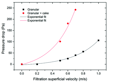
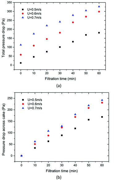
Besides collection efficiency, the pressure drop of dynamic granular filter also plays an important role in determining the energy consumption of the filter. The collection efficiency of dynamic granular filters has been examined in our previous study. Greater than 99% collection efficiency indicates that dynamic granular filters could be a promising technology for the hot gas dust removal industry.24 In the present study, we mainly focus on the pressure drop of the filter and the dust cake. Fig. 6 shows the pressure drops of the filter system, i.e., granular and cake pressure drop, and granular pressure drop only varies with filtration superficial velocity. According to eqn (4), the pressure drop across the dust cake is the pressure drop across granules subtracted from the filter system pressure drop. It can be seen from this figure that both pressure drops increase exponentially with increasing filtration superficial velocity and the increase is more significant for the filter system. As expressed in Ergun's equation, filtration superficial velocity exponentially affects the pressure drop across the dust cake, which agrees with the experimental results in this study. As a matter of fact, due to the compression of dust cake being a complex microscopic process, the pressure drop across the dust cake increases with increasing cake thickness and filtration superficial velocity, but at a different scale.Fig. 7 displays the pressure drop versus filtration time at different filtration superficial velocities. From this figure, it is observed that the total pressure drops at the beginning, i.e., pressure drop across filter granules only, are evidently different at different filtration superficial velocities. With the progress in filtration time, the total pressure drop across the filter and dust cake increases. Fig. 7b demonstrates the pressure drop across dust cake versus filtration time at different filtration superficial velocities. In general, the pressure drop across the dust cake increases with filtration time, but the pressure drop at smaller filtration superficial velocities increases relatively slowly. Similar results were reported in the study.32 This is due to the dust cake being compressed much harder at higher filtration superficial velocities, corresponding to smaller porosity, lower cake thickness and higher pressure drop of the filter. In other words, a higher filtration superficial velocity could increase the processing amount of dust laden gas, but this will also cause lower collection efficiency24 and consume more energy. A balanced consideration of the collection efficiency, energy consumption and processing amount is needed for dynamic granular filters in practical applications.
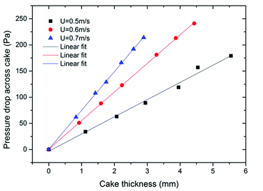
The relationship between cake thickness and pressure drop across cake is presented in Fig. 8. It is found that the increase in dust cake thickness causes linear growth of pressure drop, which can also be observed from eqn (5). Because the variation of porosity is tiny at fixed filtration superficial velocity, the inertial term of Ergun's equation is relatively small compared to the viscous term. Therefore, thickness of the dust cake is almost proportional to the pressure drop. In the case of the same thickness of dust cake, the higher the filtration superficial velocity, the larger the pressure drop it has. This is because the porosity decreases with a higher filtration superficial velocity, indicating that the cake is compressed more tightly. It can also be observed that the slope increases with increasing filtration superficial velocity, which means that the thickness is relatively thinner at a higher filtration superficial velocity. This phenomenon reflects that the compression of the dust cake is stronger and the porosity is smaller at higher filtration superficial velocity. In addition, dust laden gas has larger kinetic energy at a higher filtration superficial velocity. Thus, the layer of dust cake is compressed by the drag force caused by pressure drop until the drag force is close to the particle's maximum interparticle adhesion force and the friction angle between particulates. Then, the movement of dust particulates stops. Because dust particulates move along the direction of cake growth, the dust cake is compressed and cake porosity decreases. At higher pressure drop, the dust particulates keep moving instead of staying at the surface of the cake in a porous layer. Hence, the thickness of dust cake is relatively thinner and the increase of cake thickness is much slower.
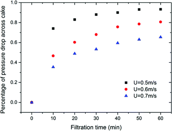
Fig. 9 shows that the percentage of pressure drop across dust cake to filter system varies with filtration time. From this figure, it can be seen that the percentage increases rapidly during the initial 10–20 minutes while the dust cake is forming. After that, the increase in the percentage becomes more slower for different filtration superficial velocities. Further, the increase tends to be gentle and remains almost constant after about 50 minutes. The final pressure drop percentage of dust cake differs for different filtration superficial velocities. The higher the filtration superficial velocity, the smaller the pressure drop percentage of the dust cake.
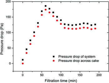
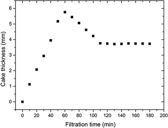
Fig. 10 presents the pressure drop across both filter system and dust cake while the operation condition transferred from fixed bed to dynamic bed at the filtration superficial velocity of 0.5 m s−1. It is found that they increase rapidly at the beginning stage and start to decline after about 50 minutes. Then the pressure drops remain almost constant when the filter changes into surface filtration stage after about 100 minutes. This indicates the essential ability of dynamic granular filters to maintain the cake thickness and pressure drop at a certain level without a blowback process. As a matter of fact, this characteristic of dynamic granular filters can improve collection efficiency and ensure appropriate system resistance. The variation of dust cake thickness with filtration time at the filtration superficial velocity of 0.5 m s−1 is illustrated in Fig. 11. As discussed before, the thickness of dust cake is difficult to exactly measure by experiment. In this study, the cake thickness is calculated by the formulated equations, see eqn (5) and (6). From Fig. 10 and 11, it is noted that the trend of calculated cake thickness is very similar with that of pressure drop from experiments, which indicates that the proposed theoretical explanation regarding dust cake formation and formula derivations are applicable for the dynamic granular filter. In addition, it is found that there is an optimum thickness of dust cake around 3.8 mm in the studied case, at which the system resistance reaches a relatively lower level.
Conclusions
The optimum thickness of dust cake and the corresponding flow rate of granular material are the key factors for designing a dynamic granular filter, which could provide guarantee for excellent collection efficiency and appropriate system resistance. In this study, we extended our previous work to investigate the process of cake formation and growth on the performances of dynamic granular filters. The main conclusions can be summarized as follows:(1) A new theoretical explanation for dust cake formation and growth has been proposed, by which the dust cake thickness and porosity can be calculated.
(2) The pressure drops of filter system and dust cake increase exponentially with increasing filtration superficial velocity. Therefore, although an increase of filtration superficial velocity could increase the processing amount of gas, it will consume more energy with lower collection efficiency. A balanced consideration should be given for dynamic granular filters in actual applications.
(3) With the progress in filtration time, the pressure drops across filter system and dust cake thickness increases rapidly at the beginning and decrease after about 50 minutes. Finally, they remain at a lower level when the filter changes into surface filtration stage. This characteristic of dynamic granular filters could improve the filtration efficiency and ensure an appropriate system resistance.
(4) The percentage of pressure drop across dust cake increases with filtration time but decreases with the increasing filtration superficial velocity. There is an optimum thickness of dust cake for dynamic granular filters, which is a critical factor providing guarantee for excellent collection efficiency at an appropriate filter system resistance.
Conflicts of interest
There are no conflicts to declare.Abbreviation
| St | Stokes number |
| Cm | Cunningham's correction factor |
| dm | Average diameter of filter medium |
| dp | Average diameter of dust particulate |
| dP | Pressure gradient |
| Pe | The Peclet number |
| K | Boltzmann constant |
| T | Absolute temperature |
| L | Average thickness of cake |
| U | Filtration superficial velocity |
| ΔPF | Pressure drop across granular |
| ΔPC | Pressure drop across dust cake |
| Pin n | Pressure value of inlet |
| Pout n | Pressure value of outlet |
| μ | Gas viscosity |
| ε | Cake porosity |
| ρp | Dust particle density |
| ρg | Gas density |
| ΔP | Pressure drop |
| Q | Mass flow rate |
| t | Filtration time |
| M | Mass of dust cake |
Acknowledgements
This study is supported by the China Postdoctoral Science Foundation (Grant No. 2017M610770) and the Fundamental Research Funds for the Central Universities (Grant No. FRF-BD-18-015A).References
- Y. Fang, D. L. Mauzerall, J. Liu, A. M. Fiore and L. W. Horowitz, Clim. Change, 2013, 121, 239–253 CrossRef CAS.
- F. Li and L.-S. Fan, Energy Environ. Sci., 2008, 1, 248–267 RSC.
- Prabhansu, M. K. Karmakar, P. Chandra and P. K. Chatterjee, J. Environ. Chem. Eng., 2015, 3, 689–702 CrossRef CAS.
- C. J. Tsai, D. R. Chen, H. Chein, S. C. Chen, J. L. Roth, Y. D. Hsu, W. Li and P. Biswas, J. Aerosol Sci., 2004, 35, 1105–1118 CrossRef CAS.
- L. Breedveld, G. Timellini, G. Casoni, A. Fregni and G. Busani, J. Cleaner Prod., 2007, 15, 86–93 CrossRef.
- N. P. Cheremisinoff, Pollution Control Handbook for Oil and Gas Engineering, John Wiley & Sons, Inc., 2016 Search PubMed.
- X. Li, Y. Hu, W. Zhang, M. Chen and Q. Li, J. Cent. South Univ., 2013, 44, 862–866 Search PubMed.
- P. V. Aravind and W. D. Jong, Prog. Energy Combust. Sci., 2012, 38, 737–764 CrossRef CAS.
- Y.-S. Chen, S.-S. Hsiau, S.-C. Lai, Y.-P. Chyou, H.-Y. Li and C.-J. Hsu, J. Hazard. Mater., 2009, 171, 987–994 CrossRef CAS PubMed.
- Y.-S. Chen, C.-J. Hsu, S.-S. Hsiau and S.-M. Ma, Energy, 2017, 120, 441–449 CrossRef CAS.
- G. Xiao, X. Wang, J. Zhang, M. Ni, X. Gao, Z. Luo and K. Cen, Powder Technol., 2013, 244, 93–99 CrossRef CAS.
- G. Xiao, X. Wang, J. Zhang, M. Ni, X. Gao, Z. Luo and K. Cen, Powder Technol., 2013, 244, 93–99 CrossRef CAS.
- Y.-Q. Zhang, P. Liang, J. Yu, J.-L. Zhu and X.-Z. Qin, RSC Adv., 2017, 7, 20266–20272 RSC.
- Y.-S. Chen and S.-S. Hsiau, Powder Technol., 2009, 192, 217–224 CrossRef CAS.
- I. Rodon, K. C. Lee, R. Pfeffer, A. M. Squires and O. K. Sønju, Powder Technol., 2005, 155, 52–61 CrossRef CAS.
- A. Y. Al-Otoom, Atmos. Environ., 2005, 39, 51–57 CrossRef CAS.
- Y. S. Chen and S. S. Hsiau, Chem. Eng. Process. Process Intensif., 2009, 48, 988–996 CrossRef CAS.
- Z. Qin and R. H. Pletcher, Adv. Powder Technol., 2015, 26, 49–55 CrossRef.
- W. Hoeflinger, H. Rud and G. Mauschitz, Sep. Purif. Technol., 2007, 58, 256–261 CrossRef CAS.
- K. J. Jeon and Y. W. Jung, Powder Technol., 2004, 141, 1–11 CrossRef CAS.
- J. J. Kim, R. Kased and T. Singh, Optim. Control Appl. Methods, 2004, 29, 257–277 CrossRef.
- J. H. Choi, S. J. Ha and H. J. Jang, Powder Technol., 2004, 140, 106–115 CrossRef CAS.
- E. Schmidt, Filtr. Sep., 1997, 34, 365–368 CrossRef.
- B. Liu, W. Zhou, P. Tan, X. Shan and Q. Yang, Powder Technol., 2016, 301, 387–395 CrossRef CAS.
- G. Yang and J. Zhou, J. China Univ. Min. Technol., 2007, 17, 201–204 CrossRef CAS.
- J. C. Bai, S. Y. Wu, A. S. Lee and C. Y. Chu, J. Hazard. Mater., 2007, 142, 324–331 CrossRef CAS PubMed.
- C. Grassi and L. Tognotti, Particulate Matter (PM), Springer Netherlands, 2008 Search PubMed.
- E. Gal, G. Tardos and R. Pfeffer, AlChE J., 1985, 31, 1093–1104 CrossRef CAS.
- R. C. Brown, H. Shi, G. Colver and S. C. Soo, Powder Technol., 2003, 138, 201–210 CrossRef CAS.
- P. V. Suresh and S. Jayanti, Environ. Sci. Pollut. Res., 2016, 1–11 Search PubMed.
- S. Ergun, Chem. Eng. Prog., 1952, 48, 89–94 CAS.
- J. Smid, Y. P. Chyou and S. S. Hsiau, Powder Technol., 2010, 203, 288–297 CrossRef CAS.
| This journal is © The Royal Society of Chemistry 2018 |

