 Open Access Article
Inkjet printing of energetic composites with high density
Chuanhao Xu a,
Chongwei An
 *ab,
Yanling Longa,
Qianbing Lia,
Hao Guoa,
Shuang Wang
 a and
Jingyu Wang*ab
aSchool of Environment and Safety Engineering, North University of China, Taiyuan, Shanxi 030051, P. R. China. E-mail: anchongwei@yeah.net; wjywjy67@163.com
bShanxi Engineering Technology Research Center for Ultrafine Powder, Taiyuan, Shanxi 030051, P. R. China
First published on 22nd October 2018
Abstract
To explore a new manufacturing method in preparing energetic composites, an inkjet printing device possessing the ability of high precision and flexibility was utilized to deposit six 3,4-dinitrofurazanofuroxan (DNTF) and hexogen (RDX) based explosive inks. The printed quality, inner structure, printed density and crystal morphology of energetic composites were tested, as well as their thermal decomposition properties and detonation properties. The results indicate that inkjet printing provides a good formation uniformity for explosive inks. Interestingly, all energetic composites exhibit excellent printed density with all values higher than 90% theoretical maximum density (TMD). Meanwhile, the composite DNTF/RDX/EC/GAP (54/36/5/5) performs best, reaching 96.88% TMD, which has reached a new height in the three-dimensional printing of energetic composites. Further study manifests that there is no appearance of new material, and the stacking manner of rodlike structures in multilayer manufacturing is the key to achieving such an amazing result. The particles in the energetic composites are spherical with the size ranging from 500 nm to 2 μm and connect with each other closely in the matrix of binders. Moreover, the energetic composites that were directly deposited into wedge channels display a good capability in steadily detonating above the size of 1 × 0.32 mm.
1 Introduction
The integration of Micro Electro-Mechanical Systems (MEMS) technology and explosive materials has been a new research orientation in the field of safe-arm devices in miniature munitions. Compared with the traditional large and bulky electro mechanical Safe-Arm devices, a MEMS safe-arm device has a smaller appearance and a higher reliability and safety in the complex environment.1 In MEMS safe-arm devices, explosive materials are commonly loaded into the built-in grooves or holes to form an explosive train on the millimetre scale, which challenges the charging methods. The conventional styles, such as press and cast can't meet the demands due to the incompatibility with MEMS technology. Thus, searching for another suitable charging style is necessary.At present, there are two charging methods used for loading explosive materials in MEMS safe-arm devices, including direct ink writing (DIW) and inkjet printing.2,3 With the precise stage platform and submillimeter nozzles, explosive materials can be loaded into grooves and holes in MEMS safe-arm devices through DIW and inkjet printing. Moreover, the nozzles and grooves don't contact with each other in the process of charging, which prevents contaminating other parts. Besides, the “wet charge” procedure, whose prepared form of explosive materials is inks during loading, improves the safety to a certain extent.
Nowadays, the commonly used technology is DIW, through which the colloidal suspensions of explosives are extruded out from nozzles and deposited into the channels or substrates to form specific shapes.2 To date, some researchers have made significant efforts in DIW and obtained great achievements,4–8 such as the CL-20 based EDF-11, which has been qualified by US army as a booster explosive.2 However, the development of inkjet printing in depositing explosive materials is relatively slow. Compared to DIW, inkjet printing is simpler for the only thing to do in the preparation of explosive ink is dissolve all desired ingredients into organic solvents. This “one-step, simple” method avoids the issues associated with particle agglomeration, growth, dispersion or clogging, and therefore attracts increasing attention to depositing and patterning energetic materials and energetic materials detection applications.9 For example, from 2011 to 2016, some scientists focused on the printing mechanism by using a DMP-2800 inkjet printer with the materials involving hexogen (RDX) and pentaerythrite tetranitrate (PETN).10,11 Unfortunately, the performances of limited printed samples were not tested due to the unreasonably slow printing speed which hinders the wide application of the inkjet printing technology.
To improve the speed, we have set up a low-cost inkjet printing device which consists of a three-axis platform and a piezoelectric-based nozzle. The assembled device can offer a higher printing speed of 3–10 ml h−1 than that of the reported inkjet printers.3 Based on it, the hexanitrohexaazaisowurtzitane (CL-20) based composite with high performance was printed in 2017.12 The density of samples was 1.7 g cm−3, reaching 86% of theoretical maximum density (TMD). However, the morphology of CL-20 changed to metastable state of β because of the addition of binders, which leads to some restrictions in application. In 2018, we printed the 3,4-dinitrofurazanofuroxan (DNTF) based composites, whose printed density achieved 1.785 g cm−3, 93.16% of TMD.13 In the field of explosive materials, for the same explosive, the strong detonation ability is mainly depended on the high charging density, which is chased in the manufacturing process. That result provided us with a direction in expanding the inkjet printing of explosive materials.
During the experiment of printing explosive ink, there is a process of recrystallization in which the solvent escapes from explosive inks. Compared to other methods, this process enables to easily produce uniform mixtures and even some new structures like co-crystals.14,15 Thus, the explosive inks including DNTF and other organic explosives will be interesting to survey. In this study, DNTF and RDX were selected as main explosives, while the ethyl cellulose (EC) and glycidyl azide polymer (GAP) were designed as binders. All components were dissolved into acetone to prepare particle-free explosive ink, which was deposited to produce energetic composite through inkjet printing devices. The properties of printed samples were tested and analysed.
2 Experimental
2.1 Materials
The particle-free explosive inks were prepared by dissolving all solutes into the organic solvent. In the study, main explosives involving DNTF (200 μm) and RDX (40–100 μm) (both provided by Gansu YinGuang Chemical Industry Co. Ltd., Baiyin, China) were dissolved in acetone (AR, produced by Tianjin Fuchen Chemical Reagents Factory, Tianjin, China), as well as EC (produced by Ninjin Country Xinda Chemical Co. Ltd., DeZhou, China) and GAP (produced by China Haohua Chemical Group Co., Ltd, Beijing, China). Before printing, the inks were passed through a 40 μm nylon mesh to remove any large, undissolved material and other contaminants which may have inadvertently entered the inks.To ensure the fast evaporation of solvent, aluminum plates which possesses a good thermal conductivity with the thickness of 1 mm were selected to be the substrates in the study. Prior to being used, the substrates were rinsed by deionized water (purchased from Shanxi YiFen Drink and Food Co. Ltd., Taiyuan, China) and then covered by ethanol (AR, produced by Tianjin Fuchen Chemical Reagents Factory, Tianjin, China) in ultrasonic cleaner for 15 minutes. Afterwards, the substrates were rinsed again by deionized water and dried in the oven at 50 °C for 20 minutes.
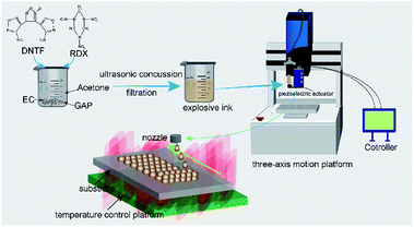
2.2 Inkjet printing device and samples generation
The device of inkjet printing which consists of a Pico Pulse piezoelectric actuator (Nordson EFD, Westlake, Ohio) and a D3 three-axis motion platform (Xiamen Twinwin Automation Technology Co. Ltd) was used to print explosive inks. In this device, the minimum volume of droplets reaches 10 nl, and the movement precision of robot arm in three-axis motion platform is 0.01 mm. The schematic diagram is shown in Fig. 1 in which the diameter of nozzle in the piezoelectric actuator used in the study is 0.1 mm.During the manufacturing, the shape of the final product was determined by the scheduled program in motion platform through which inks were deposited into the substrate and stacked layer-by-layer. The heat supplied by the temperature control platform offers the opportunity for solvent to escape from droplets printed in substrate. Built-in program in this study was a cubic whose length, width and layers were 50 mm, 7.5 mm and 400, respectively. The pulse controlling the volume of droplets was set as 0.3 ms in the study. The circulation in piezoelectric actuator and writing speed of the robot arm that determined the droplets space were set as 5.0 ms and 50 mm s−1, respectively. The distance between the nozzle and substrate was 3 mm so as to avoid the occurrence of satellites droplets. The pressure guaranteeing inks to stable transmit from syringe to nozzle was 0.05 MPa.
2.3 Characterization
The surface tension of inks was measured by a QBZY automatic surface tension meter (Shanghai Fangrui Instrument Co. Ltd). The viscosity of inks was tested by a LVDV-1 viscometer (Shanghai Fangrui Instrument Co. Ltd). To make a comparison with other scientists' results, the shear rate was set as 60 s−1, and the temperature was 25 °C. The density of inks and printed samples was tested by a MZ-220SD electronic densimeter (Shenzhen City Force Tatsu letter Instrument Co. Ltd, Shenzhen, China). The surface as well as the cross-section of printed samples were characterized with scanning electron microscopy (SEM, TESCAN Mira3, Brno, Czechia), and the cross-section of printed samples was prepared by randomly cutting method. A DX-2700 X-ray diffractometer (XRD, Dandong HaoYuan Instrument Co., Ltd, Dandong, China) was utilized to test the morphology of printed samples. Thermal properties of printed samples were measured by a Q20P Differential scanning calorimeter (PDSC, TA Instruments).3 Results
3.1 Ink formulations and inkjet printing
In the components of explosive inks, binder plays a crucial role in affecting the properties of printed samples. GAP is a promising energetic binder containing –N3 groups and is widely applied in propellants.16,17 Compared with other polymers used in composite propellants and PBXs, GAP possesses great advantages in impact sensitivity and density. Moreover, GAP is easily dissolved in organic solvents, such as ethyl acetate and acetone. The combination of these characteristics enables it to be a hopeful candidate in selecting binders used in explosive inks. However, the liquid phase of GAP hinders the direct application because of the unstable structure of the final product. Therefore, it is an urgent matter to find another binder acted as frame to keep the stability of printed samples. The EC that belongs to biologic materials has been recognized as an excellent wall material in the preparation of microcapsule, as well as drug carriers.18,19 The features of low-cost, good compatibility and great chemical stability make it a promising choice to be used as frame in the binary binder systems with GAP. In theory, the combination of EC and GAP will produce a stable structure in the final product. The ratio between EC and GAP was determined by the morphology of printed samples. It was found that a higher weight of GAP than that of EC led to a viscous product that was easily deformed. However, the final product would be very rough when the content of GAP was lower than that of EC, making the ratio of 1![[thin space (1/6-em)]](https://www.rsc.org/images/entities/char_2009.gif) :
:![[thin space (1/6-em)]](https://www.rsc.org/images/entities/char_2009.gif) 1 the optimal proportion.
1 the optimal proportion.
In order to prepare the explosive inks with printability, it is necessary to select proper solvent based on the solubility of solutes and evaporation rate. According to these two points, the acetone with the mass fraction of 84.72% was ultimately selected in the inks. The detailed formulations and their physical properties at 25 °C are summarized in Tables 1 and 2, respectively.
| Formulations | DNTF | RDX | EC | GAP | Acetone |
|---|---|---|---|---|---|
| Ink-1 | 13.86 | 0 | 0.71 | 0.71 | 84.72 |
| Ink-2 | 12.47 | 1.39 | 0.71 | 0.71 | 84.72 |
| Ink-3 | 11.09 | 2.77 | 0.71 | 0.71 | 84.72 |
| Ink-4 | 9.70 | 4.16 | 0.71 | 0.71 | 84.72 |
| Ink-5 | 8.32 | 5.54 | 0.71 | 0.71 | 84.72 |
| Ink-6 | 6.93 | 6.93 | 0.71 | 0.71 | 84.72 |
| Formulations | ρ (kg m−3) | η (mPa s) | γ (mN m−1) |
|---|---|---|---|
| Ink-1 | 880 | 1.2 | 23.33 |
| Ink-2 | 860 | 1.0 | 23.09 |
| Ink-3 | 906 | 0.8 | 23.77 |
| Ink-4 | 850 | 0.6 | 24.15 |
| Ink-5 | 884 | 0.8 | 24.52 |
| Ink-6 | 897 | 1.3 | 23.66 |
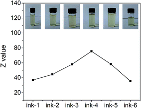
The Z values of inks from ink-1 to ink-6 are 36.94, 44.56, 58.01, 75.51, 58.2 and 35.44, respectively.
To evaluate the fluidic properties of inkjet inks, a dimensionless Fromm number Z, is defined as
 | (1) |
The images in Fig. 2 display the prepared particle-free explosive inks and their corresponding Z values, where the inks are clear and transparent without any visible particles. These inks can be stored in sealed glass bottles for several days at room temperature and kept stable without the appearance of turbid, crystallization and reduction of weight. The curve of Z values increases to the peak in ink-4, and finally reduces to the minimum in ink-6.
3.2 CT tests, density of printed samples
Computed tomography (CT) is an important technology possessing the advantage of testing samples without any damages. With the assistance of computer processing, CT is able to obtain a series of images on the basis of some physical quantities around the samples tested, such as ray velocity, intensity of X-ray and beam strength. These images contribute to further understanding of the inner structure of samples, which promotes CT to be a widely used flaw detection technology in many fields including medicine, industry and engineering.21,22 In the study, the 0.5 mm thickness of the printed sample of ink-1 (Fig. 3a) was picked for the CT test to explore the stacking compactness of inkjet printing.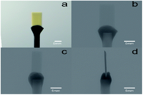 | ||
| Fig. 3 Pictures of samples in CT tests: (a) is the sample before test; (b–d) are the CT images of (a) in front view, in the angle of 45 degrees and in the angle of 90 degrees, respectively. | ||
As shown in Fig. 3a, the pale yellow composites with cuboid shape are fixed in plasticene. In CT images, if the samples have poor uniformity, different gray values will be exhibited and the darker points represent the higher density. The gray values in Fig. 3b as well as Fig. 3c and d are uniform without any obvious dark points nor any weak points. The differences between these Fig. 3 in image definition are probably ascribed to the distinction in thickness in which the thickness of tested sample in Fig. 3b is 0.5 mm, while in Fig. 3c is 7.5 mm.
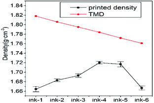
In the field of energetic materials, density is a key parameter in affecting detonation properties. Given that the explosive ink is commonly applied in micro scale explosion chain, printed density should be as high as possible. To obtain the desired explosive effect along the initiation train, a density per unit volume greater than 90% of the TMD is generally required. In this study, the printed cubic was removed from substrate for printed density tests for five times, and the TMD of printed sample for each formulation was calculated by the volume plus method.23 The details are shown in Fig. 4, which displays values of printed density of samples. The curve of printed density increases at first and then decreases reaching the values 1.664, 1.683, 1.693, 1.72, 1.717 and 1.667 g cm−3. Thus, the corresponding stacking ratio that correlated to the printed density and TMD can be calculated as 91.55%, 93.19%, 94.31%, 96.41%, 96.88% and 94.64%, respectively.
3.3 Inner structure of printed samples
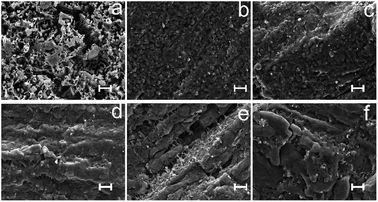
SEM test was conducted to investigate the inner morphology of printed samples. The detailed images are shown in Fig. 5 and 6 (the higher magnification of Fig. 5). From Fig. 5a–f, the cross section of printed samples presents a gradual increase in compactness. There are porous structures shown along with an obvious stratified structure in Fig. 5a, which can be attributed to the evaporation of the solvent and the filling of air during the printing processes, while Fig. 5d–f display compact dense. The Fig. 5c and d integrate the above-mentioned structures and illustrate both printing traces of layer-by-layer and dense accumulation. The thickness of layers in Fig. 5b is around 20 μm with obvious particles, while Fig. 5c presents a thinner layer without visible granules. In Fig. 5d, the one-by-one arrangement of particles illustrates an interesting dense structure compared with Fig. 5a–c. Slightly different from the previous images, dense structure also emerges in Fig. 5e and f without the appearance of particles.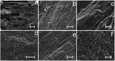 | ||
| Fig. 5 Cross section of printed samples of different formulations: (a) ink-1, (b) ink-2, (c) ink-3, (d) ink-4, (e) ink-5, (f) ink-6. The scale bar is 50 μm. | ||
 | ||
| Fig. 6 Images of Fig. 5 under a high magnification. The scale bar is 5 μm. | ||
With a higher magnification, Fig. 6a shows a dendritic structure with spherical particles connected closely at the end of branches in which clearer particles visible in all printed samples. The size of particles appeared is around 500 nm accompanied with an agglomerated lamellar structure. Compared with Fig. 6a, the particles appeared in other samples (Fig. 6b–f) are relatively larger with size ranging from 1 to 2 μm. Among the six patterns in Fig. 6b looks the most flat, while Fig. 6c–f display concave and convex shapes.
3.4 Analysis of high density for printed samples
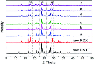
To study the effect of inkjet printing on the crystal morphology of printed samples, XRD test was conducted with diffraction angle ranging from 5 to 50. The detailed patterns are summarized in Fig. 7 in which G1 surrounded by dotted lines represents the characteristic peaks areas of DNTF, while G2 and G3 stand for RDX.Compared with raw materials, the peak intensity of G1 in the six printed samples is gradually weakening, yet G2 and G3 is getting higher and higher. This phenomenon is attributed to the content reduction of DNTF and content accumulation of RDX. Moreover, all peak widths of printed samples in G1 as well as G2 and G3 are higher than those of raw materials, probably because of the refinement of DNTF and RDX particles.24 In the view of diffraction angles, there are no new peaks for printed samples in the image, illustrating that inkjet printing does not have any influence on the crystal form of main explosives. Meanwhile, it also testifies that for printed samples prepared in this study, there are not any new composites such as co-crystals during the inkjet printing.
To probe the forming mechanism, the printed sample of ink-5 was selected to conduct a further observation in which cross section and longitudinal section were prepared by randomly cutting method. As shown in Fig. 8a, there are numerous rodlike composites cluster in the longitudinal section. In a higher magnification (Fig. 8b and c), the diameters of rodlike composites ranging from 2 to 5 μm are comprised of spherical particles with the size staying around 2 μm. In the rod, particles are nearly aligning one-by-one and closely connecting with each other by binders.
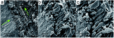 | ||
| Fig. 8 Cross section and longitudinal of the printed sample of ink-5 under different magnification: (a), (b) and (c) are 600, 2000 and 3000 times, respectively. | ||
3.5 Thermal behaviours of printed samples
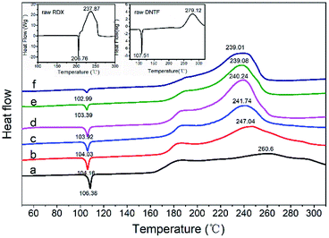
To study the thermal decomposition properties of printed samples, PDSC test was conducted at N2 atmosphere with the heating rate set as 10 K min−1. Given that the lower melting point of DNTF, the gas pressure used in the test was 2 MPa by filling the crucible with nitrogen. The detailed results are summarized in Fig. 9.In Fig. 9 (insets), the melting point and exothermic peak of raw DNTF are 107.51 °C and 279.12 °C, respectively, while the raw RDX are 206.76 °C and 237.87 °C. The images ranging from a to f in Fig. 9 exhibit the variation of thermal decomposition in which the values of melting points and exothermic peaks both decline. Moreover, there are exothermic phenomena in all curves with the exothermic peak ranging from 180 to 190 °C. Compared with raw DNTF, the melting points of six printed samples advance 1.13, 3.35, 3.48, 3.59, 4.12 and 4.52 °C, respectively. The different values of six printed samples and raw DNTF in exothermic peaks are −18.52, −32.08, −37.38, −38.88, −40.04 and −40.11 °C, respectively.
3.6 Critical size of detonation
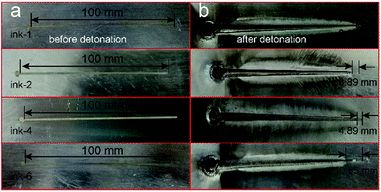
In the field of energetic composites, the critical size of detonation is a vital factor which determines the application in weapon systems. Generally speaking, energetic composites possessing the capability of detonating at micro scale size are preferred because of the development of microminiaturization in smart weapons. Herein, to verify the micro size detonation capability of printed samples, wedge-shaped charge method was selected to test the critical size of detonation where explosive inks were loaded and solidified in the wedge channel in aluminum plates.In this study, four explosive inks including ink-1, ink-2, ink-4 and ink-6 were chosen to explore the rule of main explosives changes under different contents. The optical images of printed samples are shown in Fig. 10a in which flaxen and uniform composites are situated in the channels in aluminum substrates. Then, the substrates were covered by aluminum plates and initiated using 8# electric detonator in the cylindroid charges. After detonation, the aluminum plates can be seen in Fig. 10b in which the width of channels greatly increases with the obvious propagated traces of the shock wave. Based on the explosion trace, the critical size of detonation can be calculated by formula
 | (2) |
In Fig. 10b, for four printed samples of explosive inks, B can be seen and their values are 2.33, 3.39, 4.39 and 10.55 mm, respectively. Combined with the known A and C, whose values are 100 and 3 mm, respectively, the dc can be obtained by formula (2), and the values are 0.07, 0.102, 0.132 and 0.317 mm, corresponding to the composites of ink-1, ink-2, ink-4 and ink-6.
4 Discussions
The dimensionless parameter of Ohnesorge number that evaluates the interrelations among viscous force, inertial force and surface tension is often mentioned to characterize rheological properties. The inverse of Ohnesorge number is Z, which has been widely used to assess the printability of inks in the inkjet printing systems. Fromm predicted that Z should be higher than 2 to ensure a stable drop formation.26 In 2009, Moon et al. further recommended the printable range as 4 ≤ Z ≤ 14 by considering characteristics such as single droplet formability, positional accuracy, and maximum allowable jetting frequency.27 However, the rheological properties of prepared explosive inks are significantly different from the upper researcher's results. In this study, the values ranging from 35 to 76 for Z were obtained and exhibited good printability. The main causes lie in several aspects such as the difference in inkjet printing devices and ink forms. In processing, inkjet printer is a common equipment used in reported articles, yet the device used in our study is based on a piezoelectric actuator and assembled in laboratory. In our device, the formation of droplets is mainly based on the movement of sealing ball driven by actuator, which is distinct from others'. Moreover, the inks applied in other researchers' studies focus on suspensions or solvents, which is disparate with our explosive inks.20,27In density, all printed samples exhibit an amazing stacking ratio which exceeds 90% TMD. Interestingly, the composites of ink-5 including DNTF/RDX/EC/GAP (54/36/5/5) peak among six samples and reach 96.88% TMD. In the field of 3DP for explosive materials, the ratio between actual density and TMD of solidified products in suspended explosive and particle-free explosive inks ranges from 86% to 95%, indicating that the prepared energetic composites have reached a new height.2,5,8,12,13 In further studies, there are no new peaks in XRD curves, which excludes the emergence of new structures in explosive crystals like co-crystals. Moreover, different from the prepared CL-20 based composite in our previous work in which obvious layers trace exhibited in cross section, the DNTF/RDX based printed samples of ink-5 display stronger connection properties between layers based on the rodlike structure formed. These results confirm the forming mechanism of high density, namely, the stacking manner of printed materials plays a key role in determining printed quality.
The composites possessing binary explosives perform better than the single one in printed density though the crystal density of RDX is lower than that of DNTF. In the view of inner structure, there are some printing traces left in the printed samples of ink-1 (without RDX, Fig. 5a), ink-2 (Fig. 5b) and ink-3 (Fig. 5c), where stratified structures are visible along with some holes. However, with the increasing content of RDX, this phenomenon is gradually disappearing. This effect, then, is hypothesized to be caused by a combination of effects including (a) the increasing saturation of explosive inks involving RDX, which is the result of poor solubility of RDX in acetone, and (b) the intermolecular forces between RDX and DNTF particles. In manufacturing, it will be easier for the explosive inks including RDX to approach saturation and precipitate in the thermal field. Due to the fact that the higher content of RDX for explosive inks will precipitate faster and the evaporation process of solvent will become shorter, then, there is not enough time left for filling air when ink droplets reach the solidified composite in the upper layer, resulting in a dense appearance. Moreover, there are interactions between DNTF and RDX during forming composites in which intermolecular forces affect the arrangement of particles. When the weight ratio between DNTF and RDX in the composite is 6![[thin space (1/6-em)]](https://www.rsc.org/images/entities/char_2009.gif) :
:![[thin space (1/6-em)]](https://www.rsc.org/images/entities/char_2009.gif) 4, namely the printed samples of ink-5, the intermolecular forces may reach the maximum, leading to an amazing result.
4, namely the printed samples of ink-5, the intermolecular forces may reach the maximum, leading to an amazing result.
For the printed samples of ink-1, the reduction of exothermic peak temperature in Fig. 9 may be attributed to the addition of EC because of the inexistence of energetic structure. This speculation has also been proved in other researcher's study in which GAP and DNTF had a good compatibility.19 Compared with curve a (Fig. 9), the advanced exothermic peaks from b to f are more obvious, which is ascribed to the addition of RDX. As shown in curves from b to f, the melting point of RDX does not appear at 206.76 °C, which indicates that RDX decomposes slowly in the liquid DNTF. The decomposition products obtained further accelerate the decomposition of DNTF.28 These results imply that the printed energetic composites containing RDX possess a higher activity in the thermal sensitivity.
In the critical size of detonation, the minimum value of composites formed by ink-1 is mainly attributed to the reduction of the particle size and the lower critical diameter of detonation of DNTF. As the particle sizes are similar, the main reason for the growth of dc with the increasing content of RDX among other three samples, lies in the difference between DNTF and RDX themselves in critical diameter.29 Meanwhile, it can be speculated that the critical sizes of detonation for energetic composites of ink-3 and ink-5 are mostly lower than those of ink-6. Thus, all energetic composites prepared in this study can provide a steady detonation above the charge size of 1 × 0.32 mm, which contributes to the application in micro scale channels and conforms to the trend of smart weapon systems.
5 Conclusions
In this study, the integration of inkjet printing technology and explosive materials were studied in which six explosive inks were prepared and printed to obtain energetic composites. The printed samples show good uniform property according to CT test. Moreover, the samples have high density where the ratios between printed density and TMD for six formulations all exceed 90%, reaching a new height in the 3DP of energetic materials. Further studies in exploring the potential reasons about high density exclude the production of new substances and lie in the rodlike stacking manner in the vertical direction. PDSC results illustrate that the obtained energetic composites perform more sensitive than raw DNTF in the thermal decomposition. In addition, energetic composites display a good detonation property above the charge size of 1 × 0.32 mm. This study may not only further expand the preparation of energetic composites, but also provide some references for manufacturing other materials by inkjet printing in this methodology.Conflicts of interest
The authors declare no conflict of interests.Acknowledgements
This work was supported by the Advantage Disciplines Climbing Plan of Shanxi Province.Notes and references
- R. Cope, Smaller, More Robust, Higher Reliability and Lower Cost Fuze Designs are Future Thrusts for Future Navy Fuzing, in 55th Fuzing Conference, Salt Lake City, May 2011 Search PubMed.
- D. Wang, B. Zheng, C. Guo, B. Gao, J. Wang, G. Yang, H. Huang and F. Nie, RSC Adv., 2016, 6, 112325–112331 RSC.
- A. Ihnen, W. Lee, B. Fuchs, A. Petrock, P. Samuels, V. Stepanov and A. D. Stasio, Inkjet-printing of nanocomposite high-explosive materials for direct write fuzing, in 54th Fuze Conference, Kansas City, May 2010 Search PubMed.
- Z. Q. Zhu, J. Chen, Z. Q. Qiao, B. Huang, G. C. Yang and F. D. Nie, Chin. J. Energ. Mater., 2013, 21, 235–238 CAS.
- A. Stec III, A. Wilson, B. E. Fuchs, N. Mehta and P. Cook, US Pat., 8636861 B1, 2014.
- C. Xu, C. An, H. Li, P. Ding and J. Wang, Int. J. Energ. Mater. Chem. Propul., 2016, 15, 397–411 CAS.
- C. Xu, C. An, J. Wang, B. Ye, C. Song and W. Ji, Chin. J. Energ. Mater., 2017, 25, 745–749 Search PubMed.
- Q. Li, C. An, X. Han, C. Xu, C. Song, B. Ye, B. Wu and J. Wang, Propellants, Explos., Pyrotech., 2018, 43, 533–537 CrossRef CAS.
- A. C. Ihnen, A. M. Petrock, T. Chou, P. J. Samuels, B. E. Fuchs and W. Y. Lee, Appl. Surf. Sci., 2011, 258, 827–833 CrossRef CAS.
- A. C. Ihnen, A. M. Petrock, T. Chou, B. E. Fuchs and W. Y. Lee, ACS Appl. Mater. Interfaces, 2012, 4, 4691–4699 CrossRef CAS PubMed.
- A. C. Ihnen, W. Y. Lee, B. E. Fuchs, A. M. Petrock and D. Stec III, US Pat., 9296241 B1, 2016.
- J. Wang, C. Xu, C. An, C. Song, B. Liu, B. Wu and X. Geng, Propellants, Explos., Pyrotech., 2017, 42, 1139–1142 CrossRef CAS.
- C. Xu, C. An, Y. He, Q. Li and J. Wang, Propellants, Explos., Pyrotech., 2018, 43, 754–758 CrossRef CAS.
- N. Liu, B. H. Duan, X. M. Lu, H. C. Mo, M. H. Xu, Q. Zhang and B. Z. Wang, CrystEngComm, 2018, 20, 2060–2067 RSC.
- H. Gao, W. Jiang, J. Liu, G. Z. Hao, L. Xiao, X. Ke and T. Chen, J. Energ. Mater., 2017, 35, 490–498 CAS.
- M. Guo, Z. Ma, L. He, W. He and Y. Wang, J. Therm. Anal. Calorim., 2017, 130, 909–918 CrossRef CAS.
- B. Zhao, T. Zhang, Z. Ge and Y. Luo, Sci. China: Chem., 2016, 59, 472–477 CrossRef CAS.
- S. Um-i-Zahra, X. X. Shen, H. Li and L. Zhu, J. Polym. Res., 2014, 21, 602 CrossRef.
- T. Phaechamud and J. Mahadlek, Int. J. Pharm., 2015, 494, 381–392 CrossRef CAS PubMed.
- D. Li, W. Lai, Y. Zhang and W. Huang, Adv. Mater., 2018, 30, 1704738 CrossRef PubMed.
- L. De Chiffre, S. Carmignato, J. P. Kruth, R. Schmitt and A. Weckenmann, CIRP Ann., 2014, 63, 655–677 CrossRef.
- B. R. Westerman, Int. J. Cardiovas. Imag., 2005, 21, 5–11 CrossRef.
- C. An, X. Wen, J. Wang and B. Wu, Cent. Eur. J. Energ. Mater., 2016, 13, 397–410 CrossRef CAS.
- C. An, H. Li, X. Geng, J. Li and J. Wang, Propellants, Explos., Pyrotech., 2013, 38, 172–175 CrossRef CAS.
- Department of defense test method standard. MIL-STD-1751A, safety and performance tests for the qualification of explosives (high explosives, propellants, and pyrotechnics), method 1092: very small critical diameter, 2001.
- J. E. Fromm, IBM J. Res. Dev., 1984, 28, 322–333 Search PubMed.
- D. Jang, D. Kim and J. Moon, Langmuir, 2009, 25, 2629–2635 CrossRef CAS PubMed.
- W. Zheng, J. Wang, X. Ren, L. Zhang and Y. Zhou, Propellants, Explos., Pyrotech., 2007, 32, 520–524 CrossRef CAS.
- A. A. Kotomin, A. S. Kozlov, V. V. Gorovtsov, V. V. Efanov, M. A. Trapeznikov, S. A. Dushenok and E. N. Breshev, Sol. Syst. Res., 2012, 46, 511–518 CrossRef CAS.
| This journal is © The Royal Society of Chemistry 2018 |

