
 Open Access Article
 This Open Access Article is licensed under a Creative Commons Attribution-Non Commercial 3.0 Unported Licence
Pt–Nix alloy nanoparticles: a new strategy for cocatalyst design on a CdS surface for photo-catalytic hydrogen generation
Liqun Maoab,
Qianqian Baa,
Shuang Liua,
Xinjia Jiaa,
Heng Liua,
Wei Chen ab and
Xiying Li*ab
ab and
Xiying Li*ab
aHenan Engineering Research Center of Resource & Energy Recovery from Waste, Henan University, Kaifeng 475004, PR China. E-mail: xiyingli@henu.edu.cn; Tel: +86-15237838250
bInstitute of Functional Polymer Composites, Henan University, Kaifeng 475004, PR China
First published on 10th September 2018
Abstract
Solar photocatalytic water splitting for the production of hydrogen has been a core aspect for decades. A highly active and durable photocatalyst is crucial for the success of the renewable hydrogen economy. To date, the development of highly effective photocatalysts has been seen by the contemporary research community as a grand challenge. Thus, herein we put forward a sincere attempt to use a Pt–Nix alloy nanoparticle (NP) cocatalyst loaded CdS photocatalyst ((Pt–Nix)/CdS) for photocatalytic hydrogen production under visible light. The Pt–Nix alloy NP cocatalyst was synthesized using a one-pot solvothermal method. The cocatalyst nanoparticles were deposited onto the surface of CdS, forming a Pt–Nix/CdS photocatalyst. Photocatalytic hydrogen production was carried out using a 300 W Xe light equipped with a 420 nm cut-off filter. The H2 evolution rate of the Pt–Ni3/CdS photocatalyst can reach a value as high as 48.96 mmol h−1 g−1 catalyst, with a quantum efficiency of 44.0% at 420 nm. The experimental results indicate that this Pt–Ni3/CdS photocatalyst is a prospective candidate for solar hydrogen generation from water-splitting.
1. Introduction
Hydrogen production from water splitting driven by solar energy is an admirable renewable process to secure our energy future. For decades, since the discovery of photocatalytic hydrogen production in early 1972, great effort has been focused on enhancing the quantum efficiency and durability of visible light active photocatalysts.1 The efficiency of a solar water splitting photocatalyst depends upon its ability to utilize solar radiation and electrochemically reduce protons into hydrogen molecules. Based on this fundamental understanding, significant research effort has been concentrated on designing visible-light-driven photocatalysts, including limited mixed oxides, (oxy)nitrides, and (oxy)sulfides, which have increased visible light absorption capacity.2–10 Moreover, a co-catalyst is required to be loaded onto the surface of the main semiconductor photocatalyst to store photo-generated electrons and catalyze the proton reduction reaction. Noble metals, such as Pt, Pd, Ru, and Rh, are widely recognized cocatalysts for H2 production from water splitting, as they are endowed with high activity and stability in aqueous solutions. However, the large-scale application of noble metals in energy production has been inhibited due to their scarcity and high cost.In recent years, Pt based alloy NPs have enticed the research community for use as cocatalysts, mainly due to their excellent catalytic performance in both the oxygen reduction reaction (ORR) and hydrogen oxidation reaction (HOR) in proton-exchange membrane fuel cells (PEMFCs). Pt alloy nanoparticles not only enhance the catalytic activity but also reduce Pt consumption. Pt based bi-metal alloys are excellent catalysts to meet the greater applicative requirements. So far, many Pt-based alloy catalysts (Pt–M, M = Co, Cr, Au, Pd, Ni, Cu, W, Fe, etc.) have been successfully synthesized.11,12 The reported synthetic methods for Pt–M catalysts can be summarized as follows: galvanic displacement methods, supercritical fluid deposition, electrodeless deposition, co-impregnation and the reduction of metal ions.13–18 To control the shape and crystalline facets of Pt–M NPs, most of these approaches are carried out in the presence of ligands, facet-specific capping agents, organic solvents and reductants. There are several parameters that can affect the catalytic performance of a Pt–M catalyst. These include the morphology of the nanoparticles, the Pt–M composition, particle sizes and crystal structures, particle internal defects, the atomic order (alloyed or intermetallic mixture), the shape, and exposed facets.19–21 The catalytic properties of Pt–M alloy catalysts can be significantly changed via tuning the above parameters.
Inspired by the prevailing results from PEMFCs, PtNix alloy NPs were synthesized and used as a co-catalyst with CdS in photocatalytic H2 production under visible light in this work. A hydrothermal method is utilized for the preparation of a snowflake-like CdS photocatalyst, with fluorine as a capping-reagent. A Pt–Nix alloy NP cocatalyst was synthesized using a one-pot solvothermal method and the resultant Pt–Nix alloy NPs were subsequently loaded on the surface of the CdS photocatalyst particles to form a Pt–Nix/CdS photocatalyst for solar photocatalytic hydrogen production. From the experimental data, the H2 evolution rate of the Pt–Ni3/CdS photocatalyst reaches 48.96 mmol h−1 g−1 catalyst with a quantum efficiency of 44.0% at 420 nm.
2. Experimental section
2.1. Preparation of photocatalysts
Snowflake shape CdS photocatalyst particles were prepared via a hydrothermal process, in which fluorine ions were used as a capping-reagent.22 In a typical synthetic process, 5 mmol of Cd(Ac)2·2H2O, 6 mmol of CS(NH2)2, and 0.80 mL of HF (40 wt%) were added into 79.2 mL of deionized water under stirring at room temperature. The solution was transferred into a Teflon-lined autoclave, and then heated to 473 K and kept there for 20 h, followed by cooling to room temperature. The as-obtained yellow product was separated from solution, washed with deionized water and absolute alcohol successively, dried at 333 K in a vacuum furnace for 1 day, and finally ground and stored in an airtight vial.The Pt–Nix alloy cocatalyst was synthesized via a solvothermal method.23 In a typical synthesis, a total of 0.12 mmol of platinum acetylacetonate (Pt(acac)2) and nickel acetylacetonate (Ni(acac)2) was added into 10 mL of C2H8N2 and ultrasonicated for 10 min. After that, 2.0 g of polyvinylpyrrolidone (PVP) and 2 mmol of NaBH4 were added into the solution, which was ultrasonicated until the solution became transparent. The resulting solution was then transferred into a Teflon-lined autoclave, which was heated up to 433 K and maintained there for 20 h. After cooling to room temperature naturally, the black product was collected and washed with distilled water and absolute alcohol three times, respectively. The product was dried at 333 K for 24 h in a vacuum furnace, ground to fine particles, and stored in an airtight vial.
The resulting Pt–Nix alloy NPs and 0.1 g of CdS photocatalyst were dispersed in 50 mL of 1.0 mol L−1 (NH4)2SO3 solution, which was then purged with N2 (>99.999%) for about 30 min under stirring to remove dissolved oxygen. Under irradiation from a 300 W Xe lamp, Pt–Nix alloy NPs were deposited on the surface of CdS via photo-induced electrons.24
2.2. Characterization
The morphology and particle sizes of the resultant Pt–Nix alloy NPs were recorded using a high resolution transmission electron microscope (HRTEM) (JEM-2010, JEOL Ltd., Japan), and the chemical compositions of individual nanoparticles were investigated using a scanning transmission electron microscope and high-angle annular dark-field imaging (STEM-HAADF) (Tecnai G2 F20) with an aberration corrected FEI TECNAI G2 F30 S-TWIN (S) TEM. X-ray diffraction (XRD) (Philips, XPert'Pro) with Cu Kα radiation was used to analyze the crystal structures of the as-prepared Pt–Nix alloy NPs and CdS photocatalyst, and a Pt–Ni3 alloy NP loaded CdS photocatalyst sample. The absorption properties of the Pt–Nix/CdS photocatalyst were analyzed using a UV-vis spectrophotometer UV-2450 (Shimadzu, Japan) and a FLS 980 spectrometer (Edinburgh analytical instruments, UK).2.3. Evaluation of photocatalytic activity
The photocatalytic hydrogen generation rate of the Pt–Nix/CdS photocatalyst was investigated in a water-jacketed continuously stirred tank reactor (CSTR, Φ: 125 mm) at 283 ± 1 K and under atmospheric pressure. The CSTR has a quartz window (Φ: 64 mm) on top to receive light irradiation from a 300 W Xe lamp (Beijing Perfectlight Company; Beijing, China). A cut-off filter (λ > 420 nm) was used for visible light photocatalytic hydrogen production from an ammonium sulfite (NH4)2SO3 aqueous solution. Before the reaction, 0.1 g of Pt–Nix/CdS photocatalyst powder was dispersed in 50 mL of 1.0 M (NH4)2SO3 solution. Prior to light irritation, the solution was purged with N2 (>99.999%) for about 30 min under stirring to remove the oxygen dissolved in the ammonium sulfite solution. The purity of the evolved hydrogen was monitored using a gas chromatograph (GC9560, Huaai, China), and the volume of evolved hydrogen was measured every 30 min. For an investigation into quantum efficiency (QE), the cut-off filter (λ > 420 nm) was replaced by a 420 ± 5 nm band-pass filter, and the irradiance was measured by means of an ultraviolet radiation meter (UV-B, Beijing normal University). QE can be calculated as follows:
| NH = 2 × nH2 × L |
where nH2 is the moles of evolved hydrogen molecules, mol; L is the Avogadro constant, 6.02 × 10²³ mol−1; I is the irradiance at 420 nm, W m−2; A is the illuminated area, m2; E is the photon energy, eV; h is the Plank constant, 6.63 × 10⁻³⁴ J s; and c is the light rate, 3 × 10⁸ m s−1.
3. Results and discussion
3.1. Hydrogen evolution properties
In this research, the photocatalytic activity of the prepared photocatalyst was evaluated under room pressure with (NH4)2SO3 acting as the sacrificial agent for photo-induced holes. The testing results show that CdS alone is inactive for hydrogen generation under the experimental conditions. The hydrogen generating activities of the prepared Pt/CdS and Ni/CdS were also investigated and used as baselines. Pt NPs or Ni NPs were synthesized using the same solvothermal method through which Pt–Nix alloy NPs were synthesized, except that no Pt(acac)2 or Ni(acac)2 was used. The loading of Pt NPs or Ni NPs onto the surfaces of CdS particles was also based on a photo-induced reduction method. It should be pointed out that the photo-induced reduction process of noble metal Pt was independent of cocatalyst deposition. In this method, the size and morphology of cocatalyst Pt–Nix NPs could be well controlled to overcome the impact of the loading method on the morphology. To maintain the morphology of the cocatalyst is an important aspect for understanding the effects of cocatalyst morphology on water-splitting. Fig. 1 shows the effect of Pt loading concentration on hydrogen evolution. The highest rate of hydrogen production (46.88 mmol h−1 g−1 of catalyst) can be achieved at an optimal loading of 3.0 wt% Pt on the surface of CdS. When Pt loading is less than 3.0 wt% on CdS, the rate of hydrogen production is lower than that of 3.0 wt% Pt loading due to insufficient proton reduction sites. When Pt loading is greater than 3.0 wt%, however, Pt particles partially block the incident light, reducing the number of electron–hole pairs.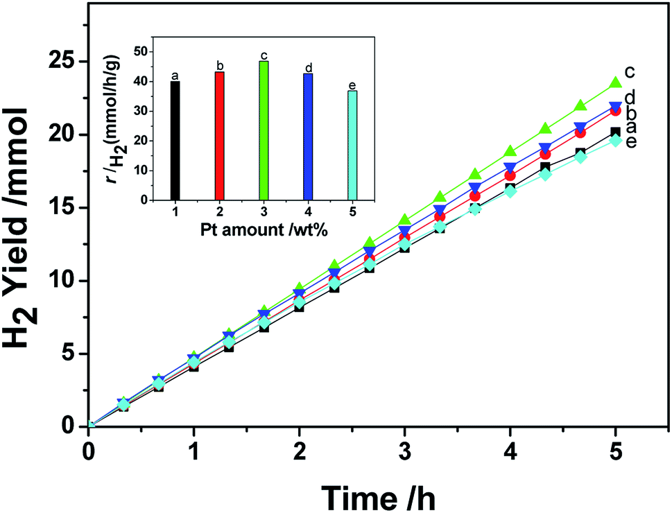 | ||
| Fig. 1 The effect of the amount of Pt NPs on the hydrogen generation rate of a CdS photocatalyst under visible light (λ ≥ 420 nm). | ||
In this work, Pt–Nix alloy NPs were synthesized via a solvothermal method and applied as a cocatalyst with CdS in photocatalytic H2 production under visible light. At a 3.0 wt% cocatalyst loading concentration, we investigated the effects of the Pt to Ni mole ratio on the photocatalytic hydrogen production rate. Fig. 2 shows that the H2 evolution rate depends on the Ni dosage in a Pt–Nix bi-metal cocatalyst. At a mole ratio of Pt/Ni = 1/3, the rate of hydrogen production reaches the maximum of 48.96 mmol h−1 g−1 cat. (QE = 44.0% at 420 nm), which is higher than that of a 3.0 wt% Pt/CdS photocatalyst (46.88 mmol h−1 g−1 cat.). These results show that the Pt–Nix alloy NP cocatalyst can promote the H2 evolution rate in comparison with a pure Pt cocatalyst, and that the mole ratio of Pt![[thin space (1/6-em)]](https://www.rsc.org/images/entities/char_2009.gif) :Ni is a critical factor for the activity of CdS in the water splitting reaction.
:Ni is a critical factor for the activity of CdS in the water splitting reaction.
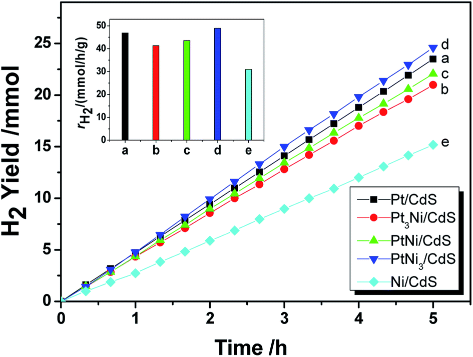 | ||
| Fig. 2 Hydrogen generation rate of the PtNix/CdS photocatalyst under visible light (λ ≥ 420 nm). | ||
Fig. 3 shows the lifetime of photocatalytic H2 production over a 3.0 wt% Pt–Ni3/CdS photocatalyst. The H2 evolution rate of the Pt–Ni3/CdS photocatalyst stabilizes at about 48.84 mmol h−1 g−1 cat. after the first cyclic photocatalytic reaction. After 5 hours of the initial reaction, the rate decreases from 48.84 mmol h−1 g−1 cat. to 41.96, 39.64, 34.67, 34.43, and 34.57 mmol h−1 g−1 cat., respectively, which might be due to the photocorrosion of CdS. The rate of hydrogen production remains constant, at about 34.5 mmol h−1 g−1 cat. after 3 cycles. These results suggest that the 3.0 wt% Pt–Ni3/CdS photocatalyst is a durable catalyst, retaining high photocatalytic activity after 30 h of photocatalytic hydrogen production.
 | ||
| Fig. 3 The time course of photocatalytic hydrogen production over a PtNi3/CdS (PtNi3 dosage: 3.0%) photocatalyst. | ||
3.2. Structural characterization
In this research, the CdS photocatalyst was prepared using a hydrothermal method with fluorine ions used as a capping reagent. The resultant CdS photocatalyst shows a snowflake-like morphology and has an average apex-to-apex distance of ∼20 mm (Fig. 4a). A typical snowflake-like CdS particle has 6 asymmetric petals, because of different preferential growth directions. Fig. 4b and c are TEM images and corresponding electron diffraction patterns from the prepared CdS photocatalyst. The snowflake-like CdS particles are single and highly crystallized particles. | ||
| Fig. 4 FESEM (a) and TEM/ED (b) & (c) images, and XRD (d), UV-vis (e), and BET (f) data from the as-prepared CdS photocatalyst. | ||
The XRD pattern from the synthesized CdS is shown in Fig. 4d. The XRD peaks are indexed as being from a hexagonal CdS phase, and the lattice constants are a = 4.14 Å and c = 6.72 Å, (space group: P63mc; PDF no. 65-3414). As shown in Fig. 4d, no impurity peaks are observed in the XRD spectrum. Compared to the standard PDF card (JCPDS no. 65-3414), the intensity of the (002) diffraction peak is much higher than that shown on the PDF card. This result suggests that the exposed crystal planes of the prepared CdS particles are {002}. This result can also be verified via TEM/SAED studies (Fig. 4c). The formation of a two-dimensional structure in the prepared CdS is due to the adsorption of fluorine ions on the (002) lattice plane during the CdS crystal nucleus stage, slowing down its growth.
Fig. 4e depicts a UV-vis diffusion reflection spectrum of the prepared CdS sample. The absorption band edge can be calculated to be 533 nm (2.3 eV). Fig. 4f shows the N2 adsorption and desorption isotherms for the prepared CdS particles. The BET specific surface area, pore volume and average pore size are 11.21 m2 g−1, 0.0274 cm3 g−1 and 3.05 nm, respectively. As shown in Fig. 4f, the adsorption–desorption isotherm can be classified as a type I curve with hysteresis loops. According to the IUPAC classification system, the N2 molecular isothermal absorption on the prepared CdS particles indicates that CdS is a mesoporous material with large pore channels. This unique structure can be beneficial for loading cocatalyst particles and forming a stable photocatalyst structure.
As mentioned in the Experimental section, Pt–Ni3 NPs were prepared via a solvothermal method with ethylenediamine as both a solvent and a reductant, and the resultant product was characterized using HRTEM, XRD, PL, etc. It can be seen from TEM images (Fig. 5a) that the average particle size of the prepared Pt–Ni3 NPs can be estimated as 4.0 nm, with a narrow size distribution. During synthesis, PVP is added as a surfactant to prevent the aggregation of nanoparticles. Nitrogen (N) and O atoms in the lactam groups of PVP molecules can coordinate with Pt–Ni3 surface atoms and inhibit the aggregation of Pt–Ni3 NPs, so that the Pt–Ni3 NPs are uniform in size and are distributed well. Fig. 5b shows a HRTEM image of the Pt–Ni3 nanoparticles, based on the area selected in the blue circle in Fig. 5a. The d spacing lattice fringes are 0.22 nm, and can be assigned to the (111) lattice plane of Pt (JCPDS no. 65-2868). This observation suggests that Pt(111) is the preferential orientation growth plane.25 A selected area (the red circle in Fig. 5a) electron diffraction (SAED) pattern of the Pt–Ni3 particles is shown in Fig. 5c. The SAED pattern shows both diffraction points and a circle, which indicates that the Pt–Ni3 NPs are very fine single crystals. In order to determine the fine structure of the Pt–Ni3 NPs, HAADF-STEM analysis was performed and a HAADF-STEM image is shown in Fig. 5d. The elemental mapping of Pt (Fig. 5e) and Ni (Fig. 5f) shows that the distribution of Pt and Ni elements within the testing area is uniform, confirming the Pt–Nix bi-metallic structure.
 | ||
| Fig. 5 A TEM image of PtNi3 NPs (a) and a HRTEM image of NPs in the blue circle (b), an SAED pattern of NPs in the red circle (c). A HAADF-STEM image of PtNi3 NPs (d), along with corresponding maps of the elements Pt (e) and Ni (f). | ||
In this work, Pt NPs were also synthesized via a solvothermal method. The method was identical to that used for the synthesis of the Pt–Nix alloy cocatalyst, except that only a pure Pt(acac)2 precursor was used. The resultant Pt NPs were observed using TEM (Fig. 6a and b). As shown in Fig. 6a and b, the morphology of the Pt NPs is spherical. The diameters of the Pt NPs range from 2 nm to 4 nm (Fig. 6a). Moreover, some Pt NPs are significantly aggregated (Fig. 6b). Fig. 6c shows prepared Ni particles. The average size of the prepared Ni NPs is ca. 5 nm, greater than that of the Pt NPs. Aggregation of the Ni NPs can also be observed (Fig. 6d). Normally, the reduction of Ni2+ ions is more difficult than the reduction of Pt2+ ions, i.e. there are insufficient crystal seeds at the beginning, and thus big particles tend to be yielded.
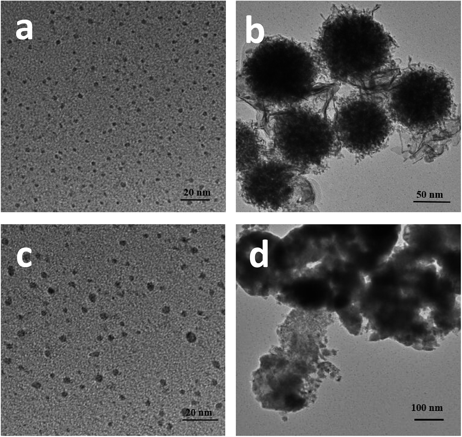 | ||
| Fig. 6 TEM images of as-prepared Pt NPs (a and b), and Ni NPs (c and d). | ||
Fig. 7 depicts XRD patterns of Pt, Ni and Pt–Ni3 nanoparticles. A Pt face-centered cubic crystal structure has five major characteristic peaks (JCPDS no. 65-2868) (Fig. 7), corresponding to (111), (200), (220), (311) and (222) crystal planes. The diffraction peaks observed at 42.2°, 44.8°, and 59.4° can be assigned to metallic Ni NPs (JCPDS no. 45-1027) (Fig. 7a). Comparing the Pt and Ni samples, the diffraction peaks from Ni NPs are sharper than those from Pt NPs, indicating that the Ni NPs have relatively higher crystallinity than the Pt NPs. The results also suggest that the average sizes of Ni NPs are greater than those of Pt NPs. This XRD analysis agrees with the TEM observations, which show the average size of Ni NPs is greater than that of Pt NPs under identical synthesis conditions. The XRD pattern of the prepared Pt–Ni3 crystalline structure is depicted in Fig. 7c. The five characteristic peaks of Pt–Nix alloy NPs are attributed to a face-centered cubic structure of metallic Pt, and no Ni peaks are found. These testing results have also been confirmed by other research groups.26–28 It is generally thought that Ni atoms might enter the interstitial spaces in the Pt crystal, because of their relative smaller atomic diameter. Moreover, compared with the XRD patterns of prepared Ni NPs and Pt NPs, the XRD peaks from Pt–Ni3 are broadened and shifted toward higher angles. This observation may be explained based on the structural contraction of Pt nano-crystals, caused by Ni atoms,26 indicating the formation of Pt–Nix alloy NPs.
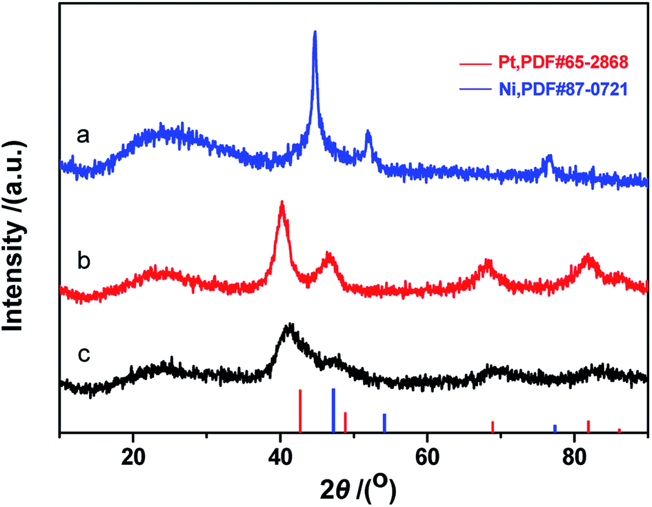 | ||
| Fig. 7 XRD patterns of the as-prepared Ni NPs (a), Pt NPs (b), and PtNi3 NPs (c). | ||
Fig. 8 shows XRD patterns of the fresh CdS photocatalyst, 3.0 wt% Pt/CdS, 3.0 wt% Ni/CdS and 3.0 wt% Pt–Ni3/CdS after the hydrogen generation reaction. Interestingly, the (002) plane intensity decreases from CdS to Ni/CdS to Pt/CdS and finally to Pt–Ni3/CdS. The hydrogen generation activity follows an opposite sequence with Pt–Ni3/CdS > Pt/CdS > Ni/CdS > CdS. Therefore, we suggest that Pt–Ni3 has high surface energy; in other words, it's most active, and tends to deposit on the surface of the CdS photocatalyst when illuminated under visible light, finally accelerating the hydrogen generation rate of the CdS photocatalyst. In fact, we also can suggest from the XRD analyses that the high activity of snowflake-like CdS might be caused by its high index surface (002). That's indeed the reason that more and more attention has been focused on the synthesis of nano-structures with high index surfaces.29,30
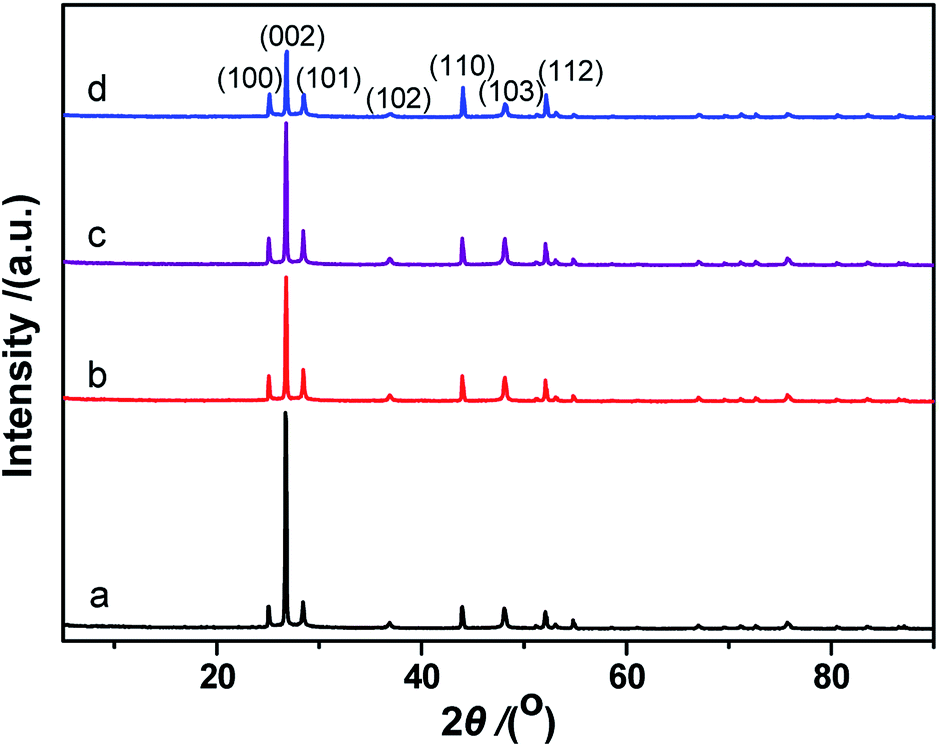 | ||
| Fig. 8 XRD patterns of CdS (a), Pt/CdS (b), Ni/CdS (c) and PtNi3/CdS (d). | ||
Table 1 lists the diffraction peak intensities of freshly prepared CdS and Pt–Ni3/CdS photocatalyst particles. It's clearly seen that after Pt–Ni3 NP loading, the peak intensities of the high index facets, (002), (101), (102) and (103), of CdS sample are significantly decreased. In particular, the intensity ratio (ICdS/IPt–Ni3/CdS) for the (002) high index facet has been reduced to 0.307. This result may indicate that Pt–Ni3 alloy NPs tend to deposit on high index facets to reduce surface energy and exposed area probabilities. High-index facets have a high surface density of low-coordinated atoms, and thus are more active for the adsorption of cocatalyst particles than low-index crystal planes, having closely packed surface atoms.31–33 However, because of their high surface energy, preserving high-index facets during the growth of nanocrystals is still a significant challenge. Moreover, their stability during subsequent applications remains unclear.
| 2θ/° | Lattice plane | I | IPtNi3/CdS/ICdS | |
|---|---|---|---|---|
| CdS | PtNi3/CdS | |||
| 25.09 | (100) | 2034 | 2119 | 1.042 |
| 26.77 | (002) | 19096 |
5872 | 0.307 |
| 28.46 | (101) | 2416 | 2107 | 0.872 |
| 36.88 | (102) | 607 | 400 | 0.659 |
| 43.97 | (110) | 1984 | 2711 | 1.366 |
| 48.12 | (103) | 1851 | 1261 | 0.681 |
| 52.09 | (112) | 1578 | 2075 | 1.315 |
3.3. Spectral analyses
UV-vis diffuse reflectance spectra (DRS) of CdS, Pt/CdS, Ni/CdS and Pt–Ni3/CdS photocatalysts are depicted in Fig. 9. The absorption edge of CdS is about 530 nm (Eg = 2.3 eV), and remains unchanged after cocatalyst loading. The DRS of Pt–Ni3/CdS exhibits a slight red shift and an increase in light absorption in the range of 250–530 nm, which might be interpreted through synergistic effects between Pt and Ni elements. However, ultraviolet analysis of Pt-based alloys is rarely reported.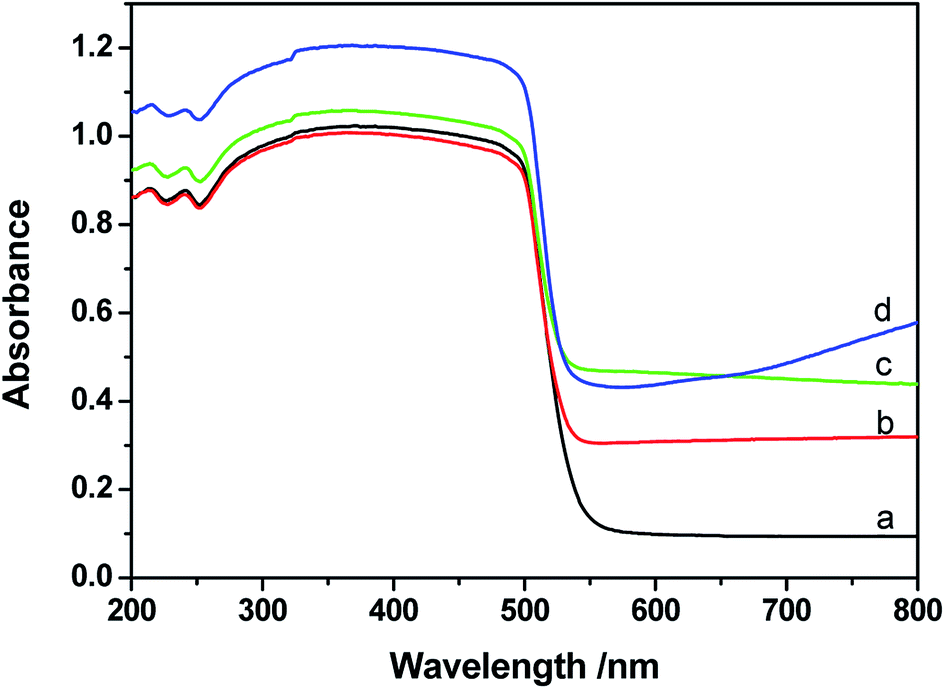 | ||
| Fig. 9 UV-vis spectra of CdS (a), Pt/CdS (b), Ni/CdS (c) and PtNi3/CdS (d). | ||
The lifespans of CdS, Pt/CdS, Ni/CdS and Pt–Ni3/CdS photocatalysts were examined using PL spectral analysis at 407 nm excitation (Fig. 10). The lifespan curves of the four photocatalysts investigated in this research are fitted well by a double exponential function. Compared to the lifespan curve of CdS, the curve for the Pt–Ni3/CdS photocatalyst shows a right shift with time. This time shift is closely related to the activity for photocatalytic hydrogen generation under visible light. Among the four photocatalysts, Pt–Ni3/CdS shows the longest lifespan. It is believed that a semiconductor photocatalyst lifespan is closely related to the life of photo-induced carrier transformation.34–38 The lifetime of a photocatalyst increases with enhanced charge separation efficiency for photo-induced electrons and holes. A higher charge separation efficiency occasionally indicates a higher photocatalytic hydrogen generation rate for a photocatalyst. From this viewpoint, we can conclude that the higher activity of the Pt–Ni3/CdS photocatalyst is attributed to its higher charge separation efficiency.
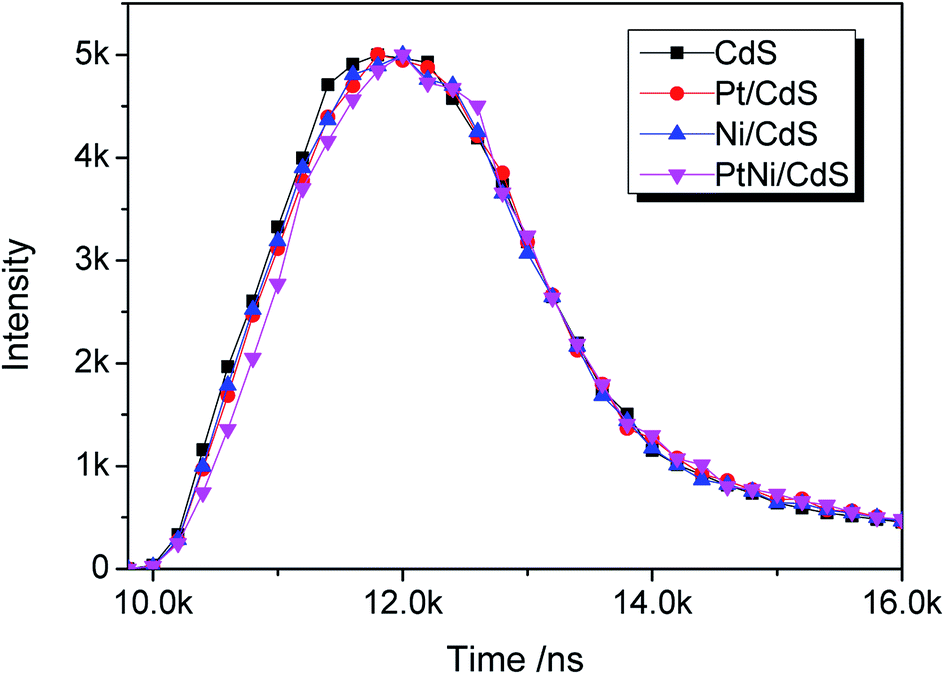 | ||
| Fig. 10 The PL life-times of the photo-catalysts when applied to the hydrogen generation reaction. | ||
3.4. Discussion
The quantum efficiency of a photocatalyst for hydrogen generation from water-splitting mainly depends on three aspects: (1) the photon absorption efficiency of the photocatalyst; (2) the charge separation and transfer efficiency of photo-induced electron and hole pairs in the bulk and at the surface of the photocatalyst; and (3) the electrocatalytic evolution of H2 and O2. In the photocatalysis field, intensive research has been focused on these three areas.In this work, the snowflake-like CdS photocatalyst shows high activity in the hydrogen generation reaction under visible light irradiation. Based on the characterization results, the high activity of snowflake-like CdS is attributed to its high index facet (002), its higher degree of crystallinity, and the snowflake sheet structure. The Pt–Nix alloy NPs deposited on the surface of the CdS photocatalyst decreased the exposure of the CdS high index (002) crystal surface facets. The intensities of the diffraction peaks of CdS and Pt–Ni3/CdS listed in Table 1 reveal that the priority sequence of deposition surfaces for the Pt–Ni3 cocatalyst particles is (002) > (102) > (103) > (101). Pt–Ni3 particles on the (002) crystal facet of CdS can be regarded as the main reason for the high activity of the Pt–Ni3/CdS photocatalyst for hydrogen generation. SEM and HRTEM results indicate that the size of the snowflake-like CdS is on the micrometer scale, with (002) being the main exposure surface. In addition, the thicknesses of the snowflake-like CdS particles are on the nano-scale. The two-dimensional structure of the prepared CdS benefits the charge transfer of photo-induced electrons from the bulk to the surface, where electrons are used for the reduction of protons.39,40 The two-dimensional structure and high energy (002) exposed surface contribute to the high activity of the prepared snowflake-like CdS photocatalyst.
Moreover, the high hydrogen production rate of the Pt–Ni3/CdS photocatalyst results not only from the structure of snowflake-like CdS but also from the Pt–Ni3 alloy co-catalyst nanoparticles. Ni atoms in the synthesized Pt–Ni3 bimetallic cocatalyst can promote electron transfer from CdS, because Ni atoms in the Pt–Ni3 alloy act as electron donors to Pt atoms and, consequently, accelerate the electron transfer rate for the reduction of protons. As a result, the alloying structure of Pt and Ni atoms can significantly promote proton adsorption on Pt atom sites to maintain the high hydrogen generation activity of Pt–Ni3/CdS photocatalaysts.
4. Conclusions
In summary, we have synthesized a Pt–Nix alloy NP based cocatalyst and loaded this onto the surface of prepared snowflake-like CdS for visible light photocatalytic hydrogen production. According to an evaluation of the activity properties, Pt/CdS reaches the highest hydrogen production rate (46.88 mmol h−1 g−1) when the Pt loading equals 3.0 wt%. Moreover, through introducing a Ni element into the Pt NPs, the rate of hydrogen production increases first and decreases afterwards, reaching a maximum of 48.96 mmol h−1 g−1 cat. (QE = 44.0% at 420 nm) when the Pt to Ni ratio is 1:3. We suggest that Ni atoms in the Pt–Nix alloy NPs function as electron donors to Pt atoms, accelerating the transfer rate of photo-induced electrons, thus promoting the hydrogen generation rate. Moreover, compared to a pure Pt cocatalyst, the most active photocatalyst, Pt–Ni3/CdS, effectively reduces the usage of Pt, showing good application prospects for hydrogen generation from water-splitting using solar energy.
Conflicts of interest
There are no conflicts to declare.Acknowledgements
This work was financially supported by the National Natural Science Foundation of China (No. 51602091).References
- A. Fujishima and K. Honda, Photolysis-decomposition of water at surface of an irradiated semiconductor, Nature, 1972, 238, 238–245 CrossRef.
- Y. Liu, Z. Wang and W. Huang, Influences of TiO2 phase structures on the structures and photocatalytic hydrogen production of CuOx/TiO2 photocatalysts, Appl. Surf. Sci., 2016, 389, 760–767 CrossRef.
- M. Hu, Y. Cao, Z. Li, S. Yang and Z. Xing, Ti3+ self-doped mesoporous black TiO2/SiO2 nanocomposite as remarkable visible light photocatalyst, Appl. Surf. Sci., 2017, 426, 734–744 CrossRef.
- X. Xu, L. Xie, Z. Li and F. Li, Ternary MgO/ZnO/In2O3, heterostructured photocatalysts derived from a layered precursor and visible-light-induced photocatalytic activity, Chem. Eng. J., 2013, 221, 222–229 CrossRef.
- S. Chen, C. Wang, B. Benjiamin R, Y. Li, C. Wang and L. Zang, Enhancement of visible-light-driven photocatalytic H2 evolution from water over g-C3N4 through combination with perylene diimide aggregates, Appl. Catal., A, 2015, 498, 63–68 CrossRef.
- C. Cheng, J. Shi, Y. Hu and L. Guo, WO3/g-C3N4 composites: one-pot preparation and enhanced photocatalytic H2 production under visible-light irradiation, Nanotechnology, 2017, 28, 164002–164015 CrossRef PubMed.
- G. Zhang, W. Zhang, D. Minakata, P. Wang, Y. Chen and J. Crittenden, Efficient photocatalytic H2 production using visible-light irradiation and (CuAg)xIn2xZn2(1-2x)S2 photocatalysts with tunable band gaps, Int. J. Energy Res., 2014, 38, 1513–1521 CrossRef.
- J. Yu, B. Yang and B. Cheng, Noble-metal-free carbon nanotube-Cd0.1Zn0.9S composites for high visible-light photocatalytic H2-production performance, Nanoscale, 2012, 4, 2670–2677 RSC.
- X. Zhou, H. Sun, H. Zhang and W. Tu, One-pot hydrothermal synthesis of CdS/NiS photocatalysts for high H2 evolution from water under visible light, Int. J. Hydrogen Energy, 2017, 42, 11199–11205 CrossRef.
- Y. Shao and L. W. andJ. Huang, ZnS/CuS nanotubes for visible light-driven photocatalytic hydrogen generation, RSC Adv., 2016, 6, 84493–84499 RSC.
- X. Zhou, Y. Gan, J. Du, D. Tian, R. Zhang, C. Yang and Z. Dai, A review of hollow Pt-based nanocatalysts applied in proton exchange membrane fuel cells, J. Power Sources, 2013, 232, 310–322 CrossRef.
- N. Jung, Y. Dong, J. Ryu, S. Song and Y. Sung, Pt-based nanoarchitecture and catalyst design for fuel cell applications, Nano Today, 2014, 9, 433–456 CrossRef.
- C. Lee and C. Tseng, Ag–Pt nanoplates: galvanic displacement preparation and their applications as electrocatalysts, J. Phys. Chem. C, 2008, 112, 13342–13345 CrossRef.
- C. Lee, C. Tseng, R. Wu, C. Wu and S. Syu, Catalytic characterization of hollow silver/palladium nanoparticles synthesized by a displacement reaction, Electrochim. Acta, 2009, 54, 5544–5547 CrossRef.
- M. Watanabe, T. Akimoto and E. Kondoh, Synthesis of Platinum-Ruthenium Alloy Nanoparticles on Carbon Using Supercritical Fluid Deposition, ECS J. Solid State Sci. Technol., 2013, 2, M9–M12 CrossRef.
- J. Rebelli, A. Rodriguez, S. Ma, C. Williams and J. Monnier, Preparation and characterization of silica-supported, group IB–Pd bimetallic catalysts prepared by electroless deposition methods, Catal. Today, 2011, 160, 170–178 CrossRef.
- S. Alerasool and R. Gonzalez, Preparation and characterization of supported Pt-Ru bimetallic clusters: strong precursor-support interactions, J. Catal., 1990, 124, 204–216 CrossRef.
- M. Liu, W. Yu, H. Liu and J. Zheng, Preparation and characterization of polymer-stabilized ruthenium–platinum and ruthenium–palladium bimetallic colloids and their catalytic properties for hydrogenation of o-chloronitrobenzene, J. Colloid Interface Sci., 1999, 214, 231–237 CrossRef PubMed.
- K. Gilroy, A. Ruditskiy, H. Peng, D. Qin and Y. Xia, Bimetallic Nanocrystals: Syntheses, Properties, and Applications, Chem. Rev., 2016, 116, 10414–10472 CrossRef PubMed.
- J. Lai, W. Niu, R. Luque and G. Xu, Solvothermal synthesis of metal nanocrystals and their applications, Nano Today, 2015, 10, 240–267 CrossRef.
- Y. Wang, N. Zhao, B. Fang, H. Li, X. Bi and H. Wang, Carbon-supported Pt-based alloy electrocatalysts for the oxygen reduction reaction in polymer electrolyte membrane fuel cells: article size, shape, and composition manipulation and their impact to activity, Chem. Rev., 2015, 115, 3433–3467 CrossRef PubMed.
- C. Li, L. Han, R. Liu, H. Li, S. Zhang and G. Zhang, Controlled synthesis of CdS micro/nano leaves with (0001) facets exposed: enhanced photocatalytic activity toward hydrogen evolution, J. Mater. Chem., 2012, 22, 23815–23820 RSC.
- M. Carpenter, T. Moylan, R. Kukreja, M. Atwan and M. Tessema, Solvothermal Synthesis of Platinum Alloy Nanoparticles for Oxygen Reduction Electrocatalysis, J. Am. Chem. Soc., 2012, 134, 8535–8542 CrossRef PubMed.
- W. Chen, S. Liu, T. Chu, Q. Ba, X. Jia and L. Mao, Controllable deposition of Pt on CdS surface and its co-catalytic mechanism, Chem. Res., 2018, 29, 233–240 Search PubMed.
- B. Zhang, X. Zhan, P. Zhao and Z. Li, Ionic liquid-mediated synthesis of unique PtPd bimetallic particles with tiny subunits for efficient electrocatalytic and catalytic applications, RSC Adv., 2015, 5, 57640–57646 RSC.
- X. Qiu, Y. Dai, X. Zhu, H. Zhang, P. Wu, Y. Tang and S. Wei, Template-engaged synthesis of hollow porous platinum–palladium alloy nanospheres for efficient methanol electro-oxidation, J. Power Sources, 2016, 302, 195–201 CrossRef.
- S. Dutta, C. Ray, S. Sarkar, A. Roy, R. Sahoo and T. Pal, Facile synthesis of bimetallic Au-Pt, Pd-Pt, and Au-Pd nanostructures: enhanced catalytic performance of Pd-Pt analogue towards fuel cell application and electrochemical sensing, Electrochim. Acta, 2015, 80, 1075–1084 CrossRef.
- T. Jeon, S. Yoo, Y. Cho, K. Lee, S. Kang and Y. Sung, Influence of Oxide on the Oxygen Reduction Reaction of Carbon-Supported Pt–Ni Alloy Nanoparticles, J. Phys. Chem. C, 2016, 113, 19732–19739 CrossRef.
- X. Huang, Z. Zhao, J. Fan, Y. Tan and N. Zheng, Amine-Assisted Synthesis of Concave Polyhedral Platinum Nanocrystals Having {411} High-Index Facets, J. Am. Chem. Soc., 2011, 133, 4718–4721 CrossRef PubMed.
- X. Xu, X. Zhang, H. Sun, Y. Yang, X. Dai, J. Gao, H. Wang, N. Yu and S. Sun, Synthesis of Pt–Ni Alloy Nanocrystals with High-Index Facets and Enhanced Electrocatalytic Properties, Angew. Chem., Int. Ed., 2014, 53, 12522–12527 Search PubMed.
- G. Somorjai, Surface science and catalysis, Science, 1985, 227, 902–908 CrossRef PubMed.
- G. Somorjai and D. Blakely, Erratum: mechanism of catalysis of hydrocarbon reactions by platinum surfaces, Nature, 1975, 258, 580 CrossRef.
- N. Tian, Z. Zhou and S. Sun, Platinum metal catalysts of high-index surfaces: from single-crystal planes to electrochemically shape-controlled nanoparticles, J. Phys. Chem. C, 2008, 112, 19801–19817 CrossRef.
- N. Tian, W. Chen and S. Sun, Spectroscopic characterization and electrocatalytic properties of core-shell Au-Pt nanoparticles, Acta Phys.-Chim. Sin., 2005, 21, 74–78 Search PubMed.
- T. Cai, M. Yue, X. Wang, Q. Deng, Z. Peng and W. Zhou, Preparation, characterization, and photocatalytic performance of NdPW12O40/TiO2 composite catalyst, Chin. J. Catal., 2007, 28, 10–16 CrossRef.
- J. Tang, Z. Zou and J. Ye, Photophysical and photocatalytic properties of AgInW2O8, J. Phys. Chem. B, 2004, 35, 14265–14269 Search PubMed.
- Q. Pan, K. Huang, S. Ni, Q. Wang, F. Yang and D. He, Fabrication and photoluminescence properties of large-scale hierarchical CdS dendrites, Mater. Lett., 2007, 61, 4773–4776 CrossRef.
- L. Spanhel, M. Haase, H. Weller and A. Henglein, Photochemistry of colloidal semiconductors. Part 20. Surface modification and stability of strong luminescing CdS particles, J. Am. Chem. Soc., 1987, 109, 5649–5655 CrossRef.
- H. Park, W. Choi and M. Hoffmann, Effects of the preparation method of the ternary CdS/TiO2/Pt hybrid photocatalysts on visible light-induced hydrogen production, J. Phys. Chem., 2008, 18, 2379–2385 Search PubMed.
- W. Wen, F. Lu, C. Chao, S. Kuga, L. Wu, Y. Huang and M. Wu, Face-to-face Interfacial Assembly of Ultrathin g-C3N4 and Antase TiO2 Nanosheets for Enhanced Solar Photocatalytic Activity, ACS Appl. Mater. Interfaces, 2017, 9, 28674–28684 CrossRef PubMed.
| This journal is © The Royal Society of Chemistry 2018 |