
 Open Access Article
 This Open Access Article is licensed under a Creative Commons Attribution-Non Commercial 3.0 Unported Licence
Synthesis and photocatalytic properties of visible-light-responsive, three-dimensional, flower-like La–TiO2/g-C3N4 heterojunction composites
Jinlong Li *a,
Lijuan Dua,
Shuaiqiang Jiaa,
Guozhe Sui*a,
Yulin Zhanga,
Yan Zhuanga,
Boxin Lia and
Zhiyong Xing*b
*a,
Lijuan Dua,
Shuaiqiang Jiaa,
Guozhe Sui*a,
Yulin Zhanga,
Yan Zhuanga,
Boxin Lia and
Zhiyong Xing*b
aCollege of Chemistry and Chemical Engineering, Qiqihar University, Qiqihar 161006, China. E-mail: jinlong141@163.com; suiguozhe@163.com; Fax: +86-452-2738205; Tel: +86-452-2738205
bCollege of Science, Northeast Agricultural University, Harbin, 150030, China. E-mail: zyxing@neau.edu.cn; Fax: +86-451-55191810; Tel: +86-451-55191810
First published on 21st August 2018
Abstract
We prepared a new three-dimensional, flower-like La–TiO2/g-C3N4 (LaTiCN) heterojunction photocatalyst using a solvothermal method. Analysis and characterization were performed by conducting scanning electron microscopy, transmission electron microscopy, X-ray diffraction, X-ray photoelectron spectroscopy, Fourier transform-infrared spectroscopy, ultraviolet-visible spectrophotometry, and nitrogen adsorption and desorption. The prepared g-C3N4 nanosheets could reach 100 nm in size and covered the TiO2 surface. A tightly bound interface formed between the g-C3N4 and TiO2, speeding up the effective transfer of photo-induced electrons. In addition, the incorporation of La3+ reduced the electron–hole recombination efficiency. Consequently, the prepared La–TiO2/g-C3N4 composite material exhibited better visible-light catalytic activity than pure TiO2.
1. Introduction
Photocatalytic degradation of organic pollutants and hydrogen production from water decomposition can improve the utilization of solar energy. Therefore, photocatalysis is considered to be an ideal green technology for solving the energy crisis and reducing environmental pollution.1,2 In recent decades, TiO2 and g-C3N4 have been widely used in photocatalysis due to their non-toxicity, chemical stability and photocatalytic activity.3–5 The close interface formed between the components of a composite semiconductor material can effectively promote the transport of photogenerated carriers, increasing the photocatalytic activity relative to those of pure semiconductors.6–8 Therefore, the development of novel TiO2/g-C3N4 heterojunction photocatalysts with excellent catalytic performance has become a topic of significant research interest.Currently, most researchers use high-temperature calcination methods9–11 or solvothermal methods12–14 to recombine TiO2 and g-C3N4. For instance, Chen et al.10 heated modified TiO2 particles and protonated g-C3N4 particles at 70 °C to prepare a TiO2/Ag/g-C3N4 composite microsphere with a particle size of 2–3 μm. Li et al.9 prepared a TiO2/g-C3N4 composite hollow sphere via a solvothermal method. In these TiO2/g-C3N4 composite materials, g-C3N4 is always uniformly attached to the TiO2 particle surface and the composite particles exhibit a uniform monodisperse relationship, but the particle size is within the micron range. Through the high-temperature calcination of a TiO2 hollow sphere with a particle size of 50–100 nm and urea, Zou et al.15 obtained a TiO2/g-C3N4 composite material. However, TiO2 microspherical particles can easily disperse in g-C3N4 particles, mainly because it is difficult to control the bulk-g-C3N4 coating on the surfaces of nanosized TiO2 particles. To control this coating effectively and obtain a well-dispersed TiO2/g-C3N4 composite material, the key is to prepare nanosized g-C3N4 lamellae.
Adding metal ions can enable catalytic materials to absorb visible light more effectively.16–18 It has been found that La is rich in electronic energy levels and that the introduction of electronic energy levels can reduce the energy gaps of catalytic materials and further increase the visible light absorption.19–21 Rong et al.22 reported that a g-C3N4 photocatalyst doped with La exhibited higher photocatalytic activity in the degradation of organic pollutants. Khalid et al.23 reported that a TiO2-graphene composite material doped with La resulted in remarkably slower electron–hole pair recombination than pure TiO2.
The main purposes of this study were to prepare a nanosized TiO2/g-C3N4 composite material and further improve the photocatalytic activity of the TiO2/g-C3N4 composite material by incorporating La3+. First, we prepared a g-C3N4 nanosheet with plenty of nanopores via thermal spalling. Then, we achieved molecular self-assembly by employing a one-step solvothermal method and successfully prepared a La (x%)–TiO2/g-C3N4 composite material with a three-dimensional, flower-like structure. During the molecular self-assembly process, the formed TiO2 crystals acted as scissors, and the g-C3N4 nanosheet was cut into increasingly smaller slices. Actually, the g-C3N4 can also loaded on many other semiconductors with matched energy band structure to construct high-efficient heterojunctions, and thus providing a new idea for fabricating g-C3N4 based composite photocatalytic materials.
2. Experimental
2.1 Materials and chemicals
Melamine (C3H6N6) was used to synthesise the g-C3N4 nanosheets. Tetrabutyl titanate (Ti(OC4H9)4) was utilized as the titanium precursor in the synthesis of nanocrystalline TiO2. Lanthanum nitrate (La(NO)3·6H2O) was employed as the metal precursor for doping TiO2. These chemicals, together with hydrofluoric acid (HF, 40 wt%), ethanol (CH3CH2OH), sodium bicarbonate (NaHCO3), tert-butyl alcohol (C4H10O), r-benzoquinone (C6H4O2), and RhB (C28H31N2O3Cl), were of analytical grade and purchased from Sigma Aldrich Co. All of the reagents were of analytical grade and were used as obtained without further purification. Distilled water was employed in all of the experiments requiring water.2.2 g-C3N4 nanosheet preparation
Yellow bulk g-C3N4 was obtained through the calcination of 5.0 g of melamine in a muffle furnace at a heating rate of 2 °C min−1 at 550 °C for 4 h. After that, which was further oxidized and peeled off. The obtained light yellow powder was tiled in a square porcelain boat and calcined at a heating rate of 5 °C min−1 at 530 °C for 2 h to obtain a white g-C3N4 nanosheet.2.3 La–TiO2/g-C3N4 hybrid preparation
First, 0.6 g of g-C3N4 nanosheet powder was added to 30 mL of anhydrous ethanol and ultrasonically dispersed for 2 h. Then, 3.0 mL of Ti(OC4H9)4 was added to 20 mL of absolute ethanol to obtain a pale yellow transparent solution. La(NO)3·6H2O was added stoichiometrically to dissolve the mixture completely into a transparent mixed solution and stirred for 30 min. The g-C3N4 nanosheet dispersion was added to the Ti(OC4H9)4 mixed solution and stirred for 30 min. Next, 1.5 mL of HF was pipetted dropwise into the resulting mixed solution and stirred for 15 min. The solution was then transferred to a 100 mL Teflon-lined high-value kettle and maintained at 160 °C for 20 h. It was subsequently cooled to room temperature, and the powder was washed several times with absolute ethanol and deionized water. The resulting sample was placed in a vacuum oven at 60 °C for 4 h. The atomic ratios of La to TiO2 were 0.5%, 1%, and 2%. For comparison, the same method was used to prepare pure TiO2.2.4 Photocatalytic activity evaluation
The photocatalytic activity of La (x%)–TiO2/g-C3N4 (LaxTiCN) in the degradation of RhB in aqueous solution was tested under visible light irradiation. A 500 W Xe lamp was employed as the light source, and the visible wavelength was adjusted using a 420 nm filter. For the experiments, 50 mg of LaxTiCN and 50 mL of RhB solution (5 mg L−1) were added to the tube reactor. The suspension was magnetically stirred in the dark for 30 min prior to each assay so that it reached adsorption equilibrium prior to irradiation. The samples were taken from the reactor at regular time intervals during irradiation and centrifuged using a high-speed centrifuge (RG-TGL-16C, Ruijiang Co.) to remove the photocatalyst. The samples were collected by centrifugation every 15 min to measure the RhB degradation by performing ultraviolet-visible (UV-vis) spectrophotometry, using the absorbance at 552.0 nm as the representative peak to determine the RhB concentration.3. Results and discussion
3.1 Characterisation of synthesized catalysts
Fig. 1 shows the X-ray diffraction (XRD) patterns of TiO2, g-C3N4, TiO2/g-C3N4 (TiCN), and LaxTiCN. Evidently, the TiO2 in all of the samples was of the anatase phase. The diffraction peaks at 25.3°, 38.0°, 48.0°, 54.1°, 62.6°, 69.6°, and 75.2° respectively correspond to the (101), (004), (200), (211), (204), (220), and (215) crystal faces of anatase (JCPDS-21-1272). Meanwhile, the peaks at 13.2° and 27.7° respectively correspond to the (100) and (002) crystal faces of g-C3N4 (JCPDS no. 87-1526). In the composite samples of TiO2/g-C3N4 and LaxTiCN, the characteristic diffraction peaks of TiO2 and g-C3N4 are observable, indicating that TiO2 and g-C3N4 constituted a composite structure.24 In addition, as compared with TiO2/g-C3N4, the diffraction peaks of La (x%)–TiO2/g-C3N4 composite samples are not shifted higher or lower, indicating that La3+ did not enter the TiO2 lattice, because the ionic radius of La3+ (0.115 nm) is much larger than that of Ti4+ (0.064 nm), and La3+ cannot replace Ti4+ in a TiO2 lattice and form lattice distortion,25 which means that La3+ ions may exist in the form of La2O3 or LaF3. However, the relevant information about La2O3 and LaF3 is not observable, because the contents of La2O3 and LaF3 were relatively small. The lattice parameters of the samples were calculated from the XRD results, which are summarized in Table 1. Compared with the TiCN, the lattice parameters of La1TiCN were almost unchanged (a little decrease), which is consistent with the above results.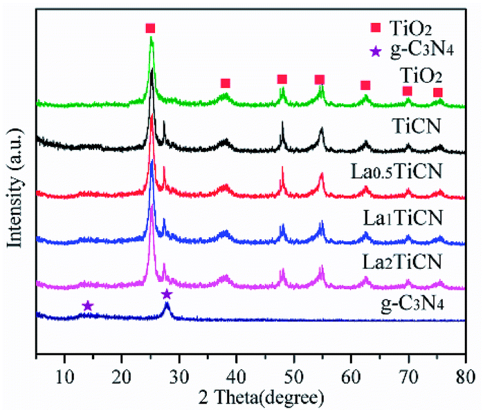 | ||
| Fig. 1 XRD patterns of TiO2, g-C3N4, TiCN, and LaxTiCN composites with various La contents. | ||
| Samples | a = b (nm) | c (nm) | Crystal size (nm) |
|---|---|---|---|
| g-C3N4 | 0.6412 | 0.2448 | 6.72 |
| TiO2 | 0.3786 | 0.9526 | 8.57 |
| TiCN | 0.3796 | 0.9512 | 8.52 |
| La1TiCN | 0.3782 | 0.9508 | 7.66 |
To demonstrate the formation of the LaxTiCN sample heterostructure, scanning electron microscopy (SEM) and transmission electron microscopy (TEM) analyses were conducted. Fig. 2a is the SEM diagram of pure TiO2. The prepared TiO2 exhibits a three-dimensional, flower-like structure, which was formed by the staggered accumulation of 500 nm lamellae. Fig. 2b presents the TEM and SEM diagrams of g-C3N4 that were obtained after secondary thermal spalling, displaying a structure with numerous pores. The size of the observed g-C3N4 nanosheet is about 100 nm, enabling the g-C3N4 to cover the TiO2 lamellae. Fig. 2c and d are SEM diagrams of the La1TiCN composite material prepared by using the one-step solvothermal method. All of the sample particles exhibit three-dimensional, flower-like structures of the same size. Compared with pure TiO2, the lamella surface of the flower-like structure of the La1TiCN is coarser and the accumulation between lamellae is denser, which is probably due to the existence of the g-C3N4 nanosheet, which provided more attachment points for the formation of TiO2 nanoparticles and enhanced the aggregation effect of the TiO2 nanoparticles during self-assembly. Fig. 2f is a TEM diagram of the La1TiCN composite material, from which it is clear that g-C3N4 nanosheet covers the surface of the TiO2 lamellae. The element mapping in Fig. 3 further proves the existence of elemental Ti, O, C, N, and La. It is evident that the Ti and O distribution diagrams can outline the basic shape of the three-dimensional, flower-like structure; the distributions of C and N are basically consistent with the material structure in Fig. 3d and e; and La is sparsely and evenly dispersed over the particle surface. The EDX spectrum confirms the presence of C, N, O, Ti, and La elements in La1TiCN and the percentage of La is 1 wt% in Fig. 3g.
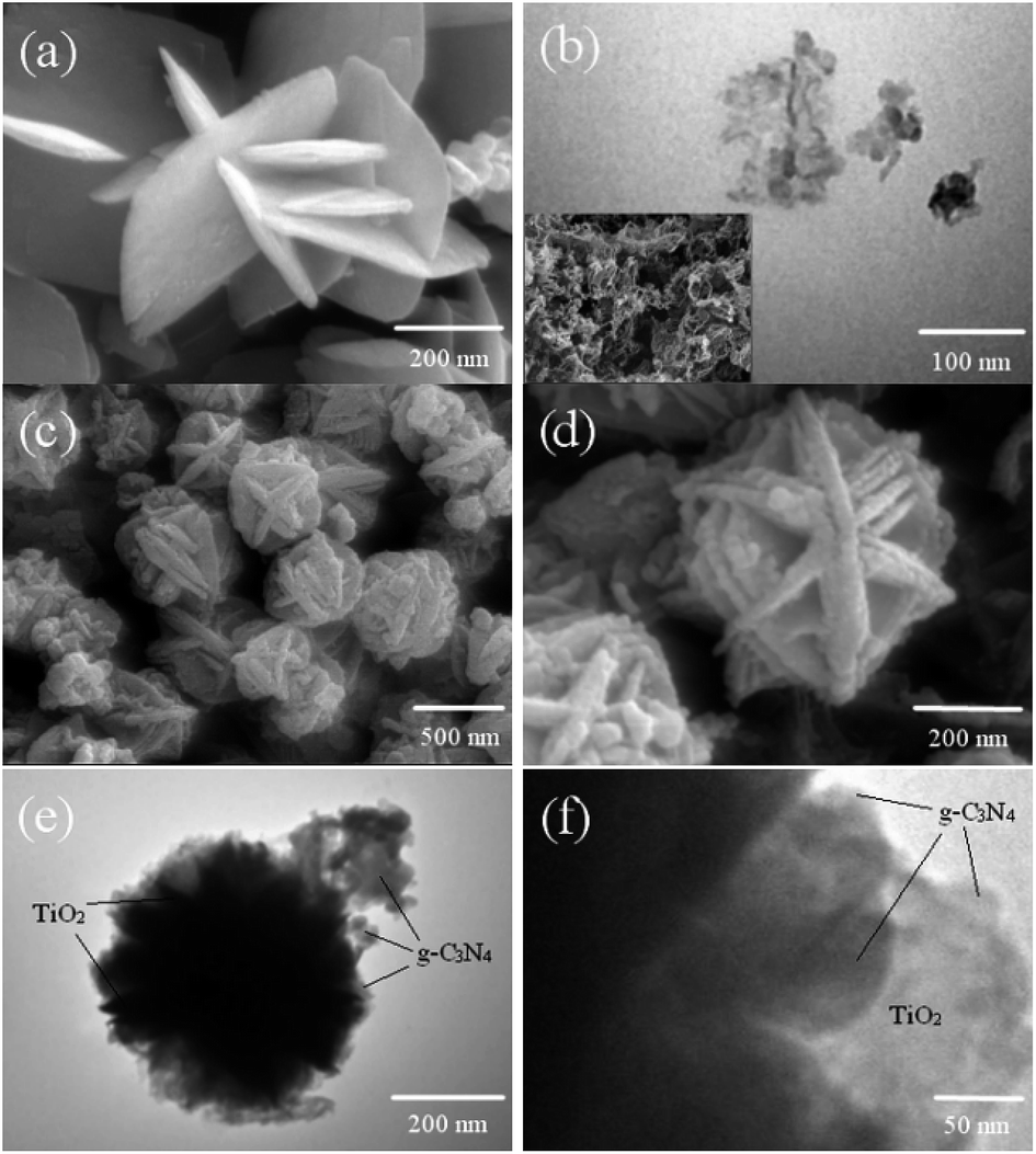 | ||
| Fig. 2 SEM images of (a) TiO2, (b) the g-C3N4 nanosheet, and (c) and (d) La1TiCN. (e) and (f) TEM images of La1TiCN. | ||
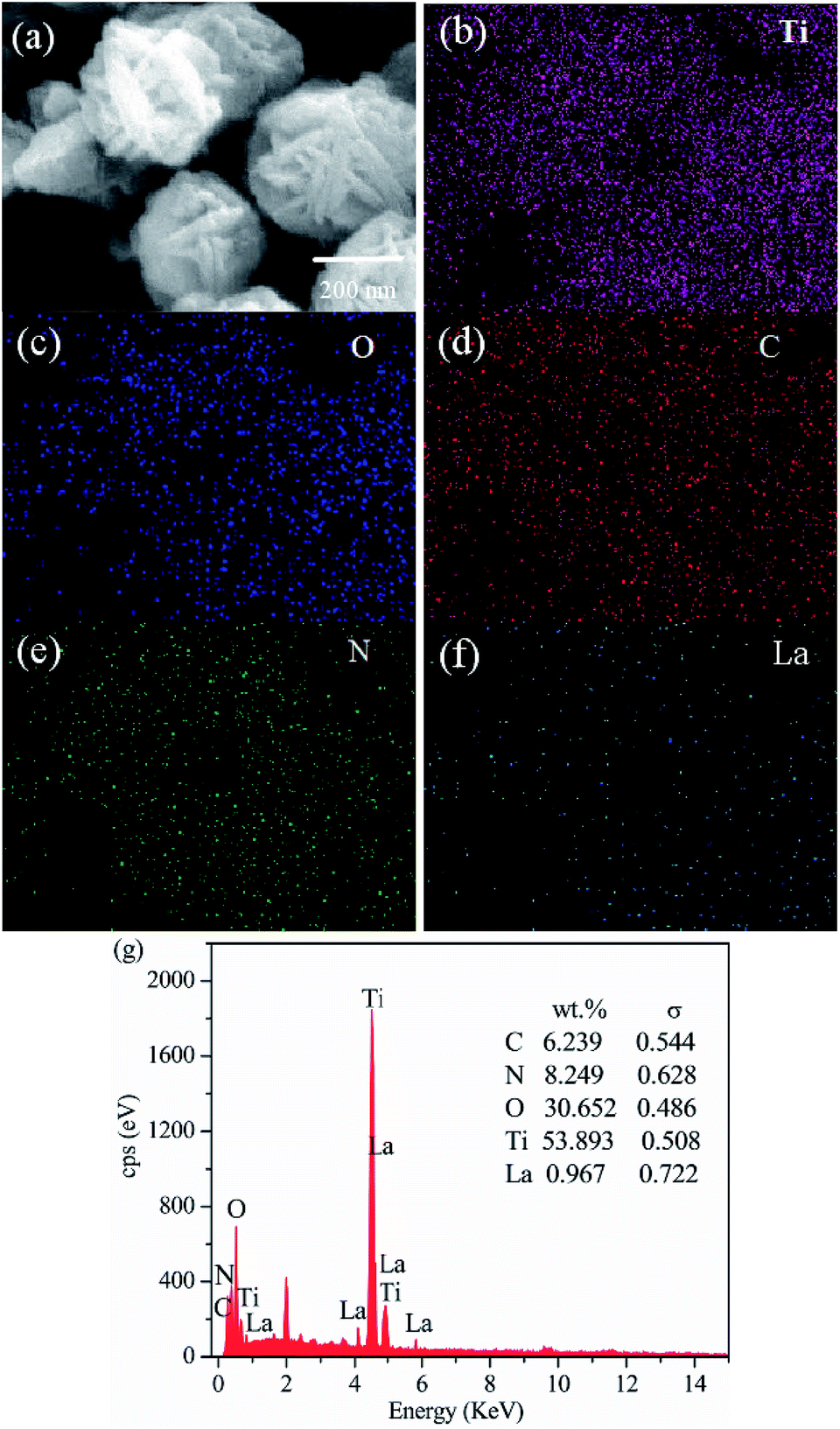 | ||
| Fig. 3 (a) TEM image of the La1TiCN sample. Corresponding energy-dispersive X-ray spectroscopy elemental mapping images of (b) Ti, (c) O, (d) C, (e) N, (f) La, and (g) EDX plots. | ||
The amount of g-C3N4 in the sample was determined by TG analysis. Fig. 4 shows a comparison of TG curves for g-C3N4, TiCN, and La1TiCN samples. Pure g-C3N4 has a large weight loss in the range of 500–700 °C. While TiCN and La1TiCN lose weight rapidly in the same temperature range, which can be attributed to the combustion of g-C3N4. Therefore, the actual amount of g-C3N4 in the TiCN and La1TiCN4 samples were about 12.77 wt% estimating from the weight loss.
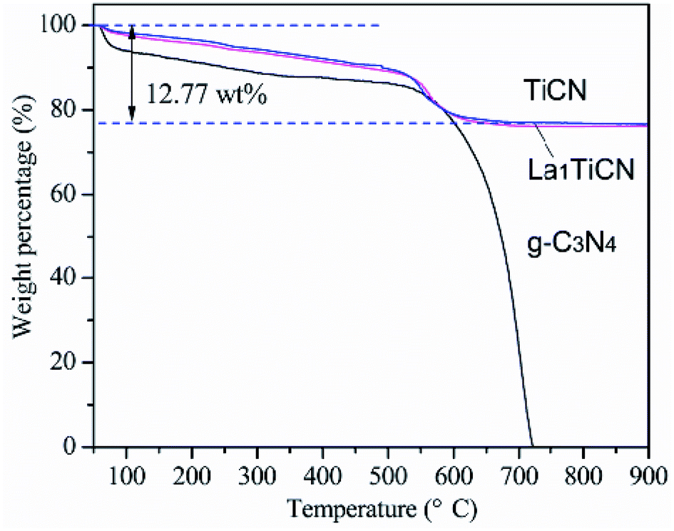 | ||
| Fig. 4 TGA curves of g-C3N4, TiCN, and LaTiCN. | ||
To determine the structural parameters of the synthesized samples, the N2 adsorption–desorption isotherms were measured in Fig. 5. The specific surface area of pure g-C3N4 is 126.5 m2 g−1, which mainly depends on the porous structure of g-C3N4. Compared with pure TiO2 (46.53 m2 g−1), the composite TiCN (62.75 m2 g−1), which is mainly produced by the deposition of the porous g-C3N4 structure onto the TiO2 surface, provides a larger surface area. The surface area of La1TiCN is 72.77 m2 g−1, indicating that La3+ can increase the surface area of the catalyst and provide more reactive centres. Fig. 4b presents the pore size distribution curves of the samples. The pure g-C3N4 pore size is 3.4 nm, while the TiO2 pore size is 5–12 nm. The main pore size of t La1TiCN presents a layered void composed of 3.8 nm (small pores) and 7.0 nm (larger mesopores). The existence of the layered void structure is beneficial to multi-light scattering/reflection, which greatly enhances the excitation.26 In addition, a hierarchical porosity composed of mesopores facilitates fast mass transport, resulting in good electrode performance.27 The similar effects from mesopores and a hierarchical porosity of the as-prepared LaxTiCN increase the photocatalytic activity.
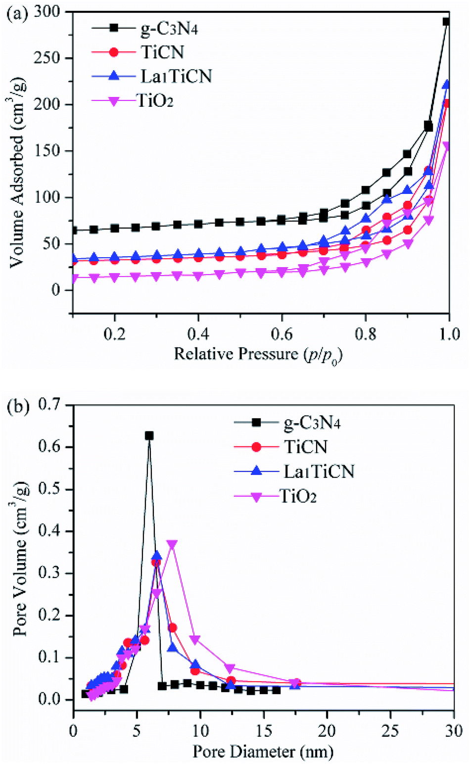 | ||
| Fig. 5 (a) N2 adsorption–desorption isotherms of TiO2, g-C3N4, and La1TiCN composites with various La contents and (b) pore size distributions of the corresponding samples. | ||
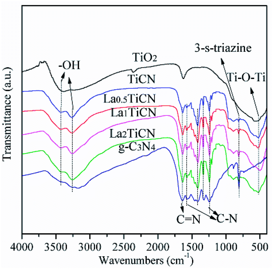
The compositions and combination modes of the TiO2, g-C3N4, TiCN, and La1TiCN samples were analysed by performing Fourier transform-infrared (FT-IR) spectroscopy. The results are shown in Fig. 6. For pure TiO2, a strong absorption peak is evident at 500–700 cm−1, corresponding to the stretching vibrations of the Ti–O and Ti–O–Ti bands, and the two strong peaks at 3350–3550 cm−1 and 1645 cm−1 are attributable to the water and hydroxy absorbed by the TiO2 surface. In the pure g-C3N4, the absorption peaks at 1239 cm−1, 1317 cm−1, 1407 cm−1, and 1571 cm−1 are attributable to the stretching vibrations of the C–N hybridized by sp3; the peak at 1637 cm−1 is attributable to the stretching vibrations of C![[double bond, length as m-dash]](https://www.rsc.org/images/entities/char_e001.gif) N hybridized by sp2; and the peak at 808 cm−1 corresponds to the out-of-plane bending vibrations of the 3-S-triazine units. For the TiCN and LaxTiCN composite samples, the main characteristic absorption peaks of TiO2 and g-C3N4 are observable, indicating that the composite heterojunction structure of g-C3N4/TiO2 formed.28 This finding is consistent with the X-ray diffraction (XRD) and X-ray photoelectron spectroscopy (XPS) results. Notably, compared with the patterns of the characteristic peaks of the pure g-C3N4 nanosheet, those of the g-C3N4 in the LaxTiCN composite sample are sharper, because the LaxTiCN composite sample had smaller g-C3N4 lamellae than the pure g-C3N4 nanosheet, causing the atoms in the g-C3N4 neighbouring 3-S-triazine ring to separate from each other and weakening the interactions among the atoms. Therefore, the atoms in g-C3N4 in the LaxTiCN samples were under less constraining force, so the vibrations were stronger.29
N hybridized by sp2; and the peak at 808 cm−1 corresponds to the out-of-plane bending vibrations of the 3-S-triazine units. For the TiCN and LaxTiCN composite samples, the main characteristic absorption peaks of TiO2 and g-C3N4 are observable, indicating that the composite heterojunction structure of g-C3N4/TiO2 formed.28 This finding is consistent with the X-ray diffraction (XRD) and X-ray photoelectron spectroscopy (XPS) results. Notably, compared with the patterns of the characteristic peaks of the pure g-C3N4 nanosheet, those of the g-C3N4 in the LaxTiCN composite sample are sharper, because the LaxTiCN composite sample had smaller g-C3N4 lamellae than the pure g-C3N4 nanosheet, causing the atoms in the g-C3N4 neighbouring 3-S-triazine ring to separate from each other and weakening the interactions among the atoms. Therefore, the atoms in g-C3N4 in the LaxTiCN samples were under less constraining force, so the vibrations were stronger.29
 | ||
| Fig. 6 FT-IR spectroscopy patterns of TiO2, g-C3N4, TiCN, and LaxTiCN composites with various La contents. | ||
Based on the analysis of the above experimental results, the formation mechanism of the LaxTiCN heterojunction catalyst was determined and is depicted in Fig. 7. First, the Ti precursor micromolecule infiltrated the gaps among the g-C3N4 lamellae. Then, the TiO2 crystal grew on the lamella surface of g-C3N4 and formed a sheet structure. The g-C3N4 was divided into increasingly smaller lamellae, and La3+ was deposited on the crystal surface. Finally, the obtained composite lamellae formed a La (x%)–TiCN heterojunction catalyst with a three-dimensional, flower-like structure in a hydrotherm through self-assembly. During the formation of the samples, the generation of small g-C3N4 through cutting during the formation of the TiO2 crystal and through the formation of smaller g-C3N4 particles was the key to the formation of the heterojunction structure.30
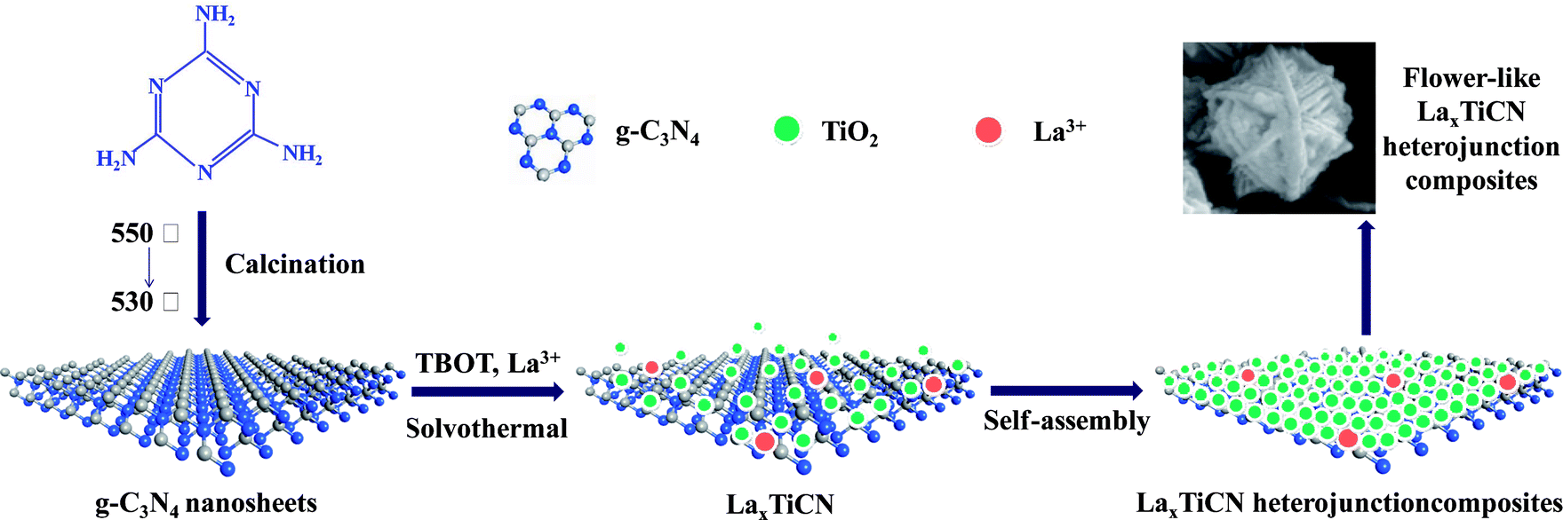 | ||
| Fig. 7 Schematics illustrating LaxTiCN formation. | ||
The chemical compositions of the prepared LaxTiCN samples and the chemical states of all of the elements were analysed by performing XPS. Fig. 8a shows the full XPS results for the La1TiCN sample, where the spectral peaks of C 1s, N 1s, Ti 2p, O 1s, and La 3d are easily observable, indicating that the sample was mainly composed of C, N, Ti, O, and La. Notably, a weak F 1s peak is evident at 684.3 eV, which is probably attributable to the fluorination caused by the introduction of HF into the preparation process.31
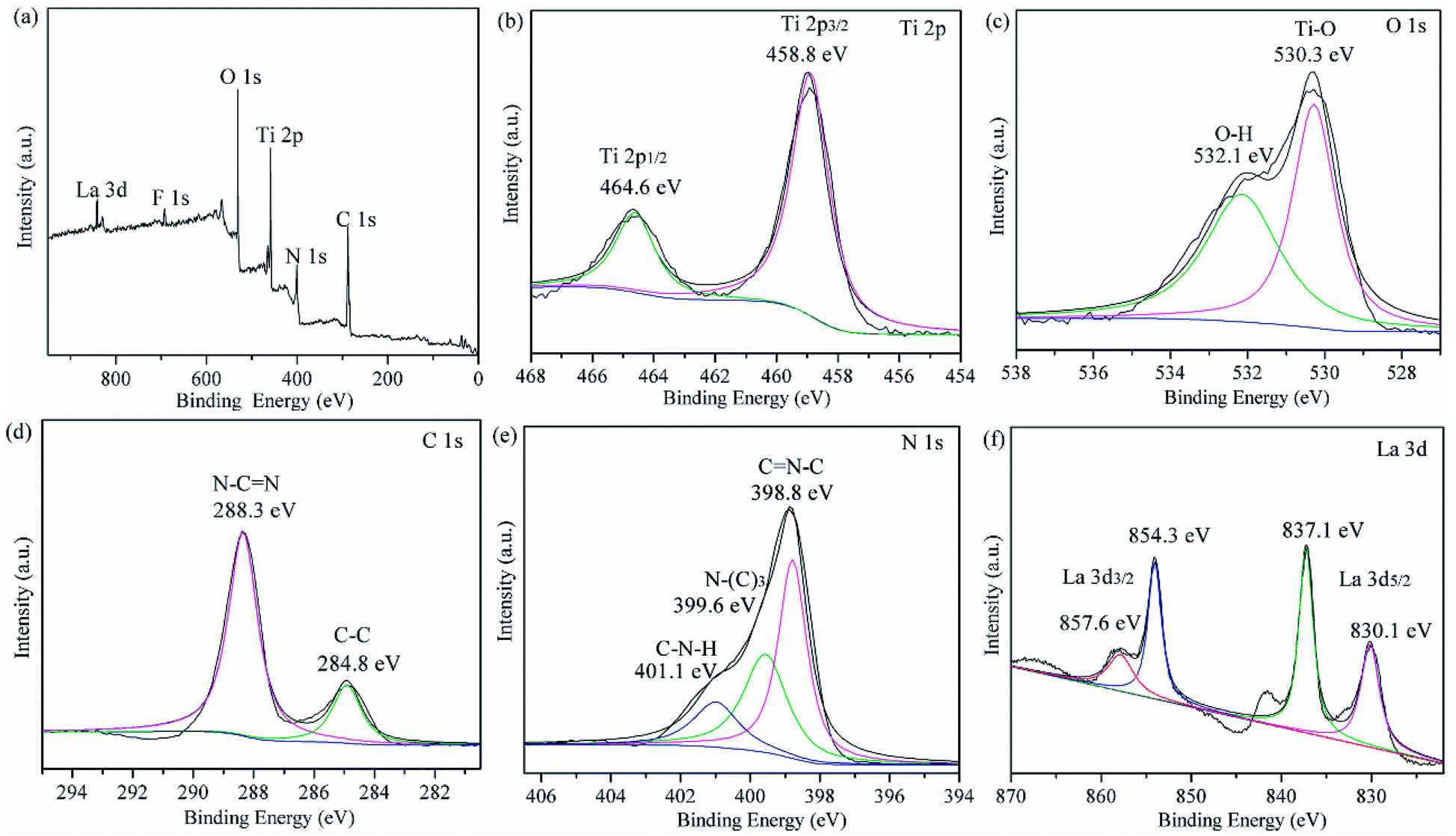 | ||
| Fig. 8 (a) Overview of the XPS results and individual high-resolution XPS results for (b) Ti 2p, (c) O 1s, (d) C 1s, (e) N 1s, and (f) La 3d of as-prepared La1TiCN. | ||
Fig. 8b presents the XPS results for Ti 2p, exhibiting two peaks at 459.4 eV and 465.1 eV, which respectively correspond to the Ti 2p3/2 and Ti 2p1/2 orbitals. Fig. 8c shows the XPS results for O 1s. The peak at 530.3 eV corresponds to Ti–O in the TiO2 lattice, and that at 532.1 eV is attributable to the hydroxy or adsorbed water molecules on the sample surface. Fig. 8d presents the XPS results for C 1s, where there are two characteristic peaks at 284.8 eV and 288.3 eV, which are attributable to the C–C bands hybridized by sp3 in g-C3N4 and the N–CN bands hybridized by sp2, respectively. Three peaks can be fitted from the XPS results for N 1s in Fig. 8e: CN–C at 398.8 eV, N–(C)3 at 399.6 eV, and C–N–H at 401.1 eV. In addition, no significant Ti–C (C 1s 283.0 eV)32 or Ti–N (N 1s 399.3 eV)33,34 signal is observable, and the binding energy of Ti 2p3/2 does not shift lower,34 indicating that atomic C and N were not incorporated into the TiO2 lattice. An additional explanation is that the g-C3N4 particles in the compound were only deposited on the surface of the TiO2, forming a heterojunction structure.
Fig. 8f presents the XPS results for La 3d, showing peaks at 837.1 eV and 854.3 eV, which respectively correspond to La 3d5/2 and La 3d3/2, as well as satellite peaks at 841.5 eV and 857.6 eV, which were respectively split by La 3d5/2 and La 3d3/2. According to the literature, the characteristic peaks of La2O3 are located at 834.9 eV and 851.8 eV,35 indicating that La3+ in the LaxTiCN sample and elemental O with stronger electronegativity formed Ti–O–La, and the binding energy shifted higher.36 These findings agree with the XRD results.
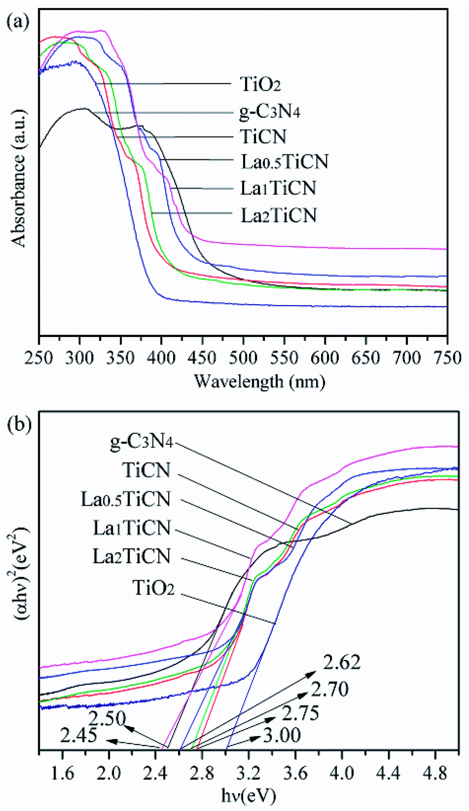
UV-vis diffuse reflectance spectrometry was then conducted to measure the absorbances of the samples. Fig. 9a shows the UV-vis diffuse reflection spectra of the g-C3N4, TiO2, TiCN, and LaxTiCN composite catalysts. The absorption edge wavelengths of the pure TiO2 sample and g-C3N4 are about 390 nm and 460 nm, respectively. Compared with the absorption edge of the pure TiO2 particles, that of the TiCN composite sample is shifted towards longer wavelengths and displays strong absorption in the 380–430 nm range, because the interface matching effect between TiO2 and g-C3N4 changed the optical properties of TiO2.37 When doped with La3+, La0.5TiCN and La1TiCN display stronger visible light absorption in the 380–450 nm range. La1TiCN exhibits the best visible light absorption, while that of La0.5TiCN is slightly weaker, probably because the La3+ concentration was too low and could not provide more electronic row traps.38 Meanwhile, for the La2TiCN sample, the UV and visible light absorption are both significantly lowered, because an excessively high La3+ concentration can reduce the light transmittance of the catalysts and light absorption efficiency.39
 | ||
| Fig. 9 (a) UV-vis diffuse reflection spectra and (b) plots of (αhv)2 versus energy hv for the catalysts. | ||
The band-gap energies of the samples were estimated by performing Kubelka–Munk conversion, and the results are shown in Fig. 8b. The band-gap energies of pure TiO2, g-C3N4, TiCN, and La1TiCN are respectively 3.00 eV, 2.50 eV, 2.78 eV, and 2.45 eV. The La1TiCN sample has a lower band-gap energy, probably because the introduction of La3+ led to the formation of a new impurity energy level in the TiO2 band gap, narrowing its band gap and extending its light absorption range.40
3.2 Photocatalytic activity and photodegradation mechanism
Under visible light irradiation, the photocatalytic efficiencies of the various samples were determined based on the RhB degradation, with the results shown in Fig. 10a. The photocatalytic activities of the various samples were further compared by using the equation ln(C0/C) = kt, where C0 is the initial RhB concentration, C is the instantaneous RhB concentration at time t, and k is the kinetic constant.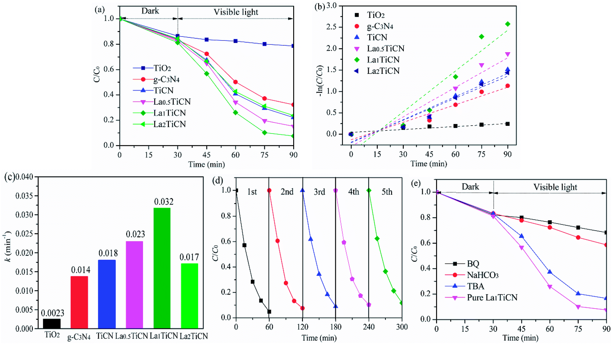 | ||
| Fig. 10 (a) Photocatalytic degradation of RhB under visible light irradiation, (b) linear transforms – ln(C/C0) of the kinetic curves of RhB degradation, (c) apparent pseudo-first-order rate constant kapp with different catalysts, (d) recycling of the La1TiCN in the removal of RhB dyes, and (e) scavenger test results obtained using La1TiCN. | ||
The first-order kinetic model of RhB degradation was obtained, with the results presented in Fig. 10b and the calculated k values given in Fig. 10c. Compared with the photocatalytic efficiencies of pure TiO2 and g-C3N4, those of all of the LaxTiCN composite samples are increasingly enhanced, mainly because the large and dense hetero interface formed between TiO2 and g-C3N4 could speed up the efficient electron–hole shifting. In addition, along with continuously increasing La3+, the photocatalytic efficiencies of the La0.5TiCN and La1TiCN samples are increasingly enhanced. The photocatalytic efficiency of La1TiCN is 95.2%, and the kinetic constant is 0.0325 min−1, which is 2.1 and 10 times those of pure TiO2 and g-C3N4, respectively, and 1.63 times that of LaxTiCN. Incorporating La3+ can firstly provide more electron traps and improve the electron–hole separation efficiency in La1TiCN. In addition, incorporating La3+ can increase the specific surface area of TiCN, with the strongest photocatalytic effect. Notably, the photocatalytic effect of La2TiCN is reduced, because excessive La3+ can serve as the recombination centre of electron–holes, reducing the photocatalytic activity of La2TiCN. For evaluating the recyclability of the flower-like LaxTiCN heterojunction composites, cycling experiments were performed by washing the composite with ethanol for several times. As shown in Fig. 10d, the photocatalytic efficiency of RhB decreases from 95.2 to 88.3% for La1TiCN after five cycles. This fact demonstrates that the obtained flower-like LaxTiCN heterojunction composites have good stability under visible-light irradiation and are less photo-corroded during the photocatalytic oxidation, which can be applied as a new option for dye wastewater treatment.
To determine the reactive species during a light-catalysed reaction, it is possible to eliminate holes h+, superoxide radicals ·O2−, and hydroxyl radicals ·OH by adding NaHCO3, BQ, and TBA. The obtained results are shown in Fig. 9d. It is evident that adding NaHCO3 and BQ significantly inhibited the light degradation of RhB in the La1TiCN sample, indicating that under visible light irradiation, O2− and h+ are the main active substances in RhB photolysis. The equations EVB = χ − Ee + 0.5BG and ECB = EVB − BG were then employed to calculate the VB and CB potentials, EVB and ECB, respectively, where BG is the band gap, χ is the absolute electronegativity of the semiconductor, and Ee is the energy of free electrons based on the hydrogen scale and has a value of 4.50 eV.41 For TiO2 and g-C3N4, χ is 5.81 and 4.72, respectively.
The VB and CB edge electric potentials of TiO2 and g-C3N4 were calculated. The VB and CB edge potentials of TiO2 were determined to be +2.83 eV and −0.17 eV, respectively, and those of g-C3N4 were found to be +1.47 eV and −1.03 eV, respectively.
Under visible light irradiation, the electrons from the VB of TiO2 and g-C3N4 were respectively excitated into the CB and left positively charged holes in the VB. Since the CB of g-C3N4 (−1.03 eV) has a potential lower than that of TiO2 (−0.17 eV), the excitated electrons on the g-C3N4 surface can easily shift to the TiO2 surface through the hetero interface.42 Finally, these electrons can be captured by the La3+ with free orbitals.43 The electrons accumulated on the La3+ surface can easily be captured by the O2 dissolved in solution to generate superoxide ·O2−, and the generated ·O2− can subsequently be used to degrade RhB. Similarly, the holes in the VB of TiO2 can easily be transferred to the VB of g-C3N4. Compared with ·OH/OH− (1.99 eV vs. NHE) and ·OH/H2O (2.68 eV vs. NHE),11 the reduction potential of the VB of g-C3N4 is even lower (1.65 eV vs. NHE). Therefore, the holes in the VB of g-C3N4 can be used to degrade RhB directly. Fig. 11 illustrates the LaxTiCN heterojunction degradation mechanism. The close interface formed by TiO2 and g-C3N4 is a green channel for electron passage, which is beneficial to increase the transfer rate of g-C3N4 photoelectrons. The proper amount of La is introduced, the interface barrier of La and TiO2 becomes higher and the space charge region is narrowed in the system. The generated large electric field promotes the light-induced electron orientation of g-C3N4 to the interface between La and TiO2, and the electron–hole recombination is effectively prevented in this process. Thus, during the photocatalytic reaction, h+ and ·O2− are the most important active species, which is consistent with the results of the active component trapping experiment. In addition, the hetero interface formed between TiO2 and g-C3N4 can facilitate charge transfer among the particles, and the incorporation of La3+ can help enhance the electron–hole pair separation efficiency in such a three-way catalytic system and further promote the photocatalytic efficiency.
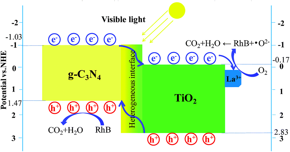 | ||
| Fig. 11 Proposed visible light photodegradation mechanism of the La1TiCN hybrid photocatalyst. | ||
4. Conclusion
LaxTiCN heterojunction composites were fabricated successfully using a simple hydrothermal method. The prepared composite catalysts exhibited enhanced photocatalytic activity compared to that of pure TiO2 under visible light irradiation for RhB degradation. The tightly connected interface between the TiO2 and g-C3N4 contributed to the stable transmission of photo-generated electrons, and La3+ could trap electrons, thereby hindering electron–hole recombination. The mutual synergy between the three-way catalytic systems effectively improved the separation efficiency of the electron–hole pairs. The prepared three-dimensional, flower-like LaxTiCN proved capable of exhibiting a strong visible light response and is potential for the removal of environmental pollutants originating from industrial wastewater.Conflicts of interest
There are no conflicts to declare.Acknowledgements
This work was supported by the Research Project of Education Ministry of Heilongjiang Province of China (YSTSXK201843, 135209223), the Research Innovation Program for College Graduates of Qiqihar University (YJSCX2017-033X) and the Research Project of the Ministry of Human Resources and Social Security of China (2015).Notes and references
- T. J. Zhu, J. Li and Q. S. Wu, ACS Appl. Mater. Interfaces, 2011, 3, 3448–3453 CrossRef PubMed.
- M. Ahmadi, H. R. Motlagh, N. Jaafarzadeh, A. Mostoufi, R. Saeedi, G. Barzegar and S. Jorfi, J. Environ. Manage., 2017, 186, 55–63 CrossRef PubMed.
- L. Jiang, X. Yuan, Y. Pan, J. Liang, G. Zeng, Z. Wu and H. Wang, Appl. Catal., B, 2017, 22, 388–406 CrossRef.
- K. X. Zhu, W. J. Wang, A. Meng, M. Zhao, J. H. Wang, M. Zhao, D. L. Zhang, Y. P. Jia, C. H. Xu and Z. J. Li, RSC Adv., 2015, 5, 56239–56243 RSC.
- J. Wang, J. Huang, H. Xie and A. Qu, Introd. Hydrogen Energy, 2014, 39, 6354–6363 CrossRef.
- C. S. Selvam and K. J. Wan, RSC Adv., 2016, 6, 10487–10497 RSC.
- J. L. Li, T. Liu, G. Z. Sui and D. S. Zhen, J. Nanosci. Nanotechnol., 2015, 15, 1408–1415 CrossRef PubMed.
- J. Li, E. Liu, Y. Ma, X. Hu, J. Wan, L. Sun and J. Fan, Appl. Surf. Sci., 2016, 364, 694–702 CrossRef.
- L. J. Zhang, M. X. Li, Q. Y. Li and J. J. Yang, Appl. Catal., B, 2017, 212, 106–114 CrossRef.
- Y. F. Chen, W. X. Huang, D. L. He, Y. Situ and H. Huang, ACS Appl. Mater. Interfaces, 2014, 6, 14405–14414 CrossRef PubMed.
- L. Ma, G. H. Wang, C. J. Jiang, H. L. Bao and Q. C. Xu, Appl. Surf. Sci., 2017, 430, 263–272 CrossRef.
- R. R. Hao, G. H. Wang, C. J. Jiang, H. Tang and Q. C. Xu, Appl. Surf. Sci., 2017, 411, 400–410 CrossRef.
- K. Wei, K. X. Li, L. S. Yan, S. L. Luo, H. Q. Guo, Y. H. Dai and X. B. Luo, Appl. Catal., B, 2018, 222, 88–98 CrossRef.
- Z. W. Li, G. D. Jiang, Z. H. Zhang, Y. Wu and Y. H. Han, J. Mol. Catal. A: Chem., 2016, 425, 340–348 CrossRef.
- Y. J. Zou, J. W. Shi, D. D. Ma, Z. Y. Fan, L. Lu and C. m. Niu, Chem. Eng. J., 2017, 322, 435–444 CrossRef.
- J. L. Li, S. Q. Jia, G. Z. Sui, L. J. Du and B. X. Li, RSC Adv., 2017, 7, 34857–34865 RSC.
- L. Zhou, L. Z. Wang, J. Y. Lei, Y. D. Liu and J. L. Zhang, Catal. Commun., 2016, 89, 125–128 CrossRef.
- L. Y. Shen, Z. P. Xing, J. L. Zou, Z. Z. Li, X. Y. Wu and Y. C. Zhang, Sci. Rep., 2017, 7, 41978–41984 CrossRef PubMed.
- Z. L. Shi, M. Guo, L. J. Wang and S. H. Yao, Chin. J. Chem. Phys., 2016, 29, 199–204 CrossRef.
- Q. J. Zhang, Y. Fu, Y. F. Wu and T. Y. Zuo, Eur. J. Inorg. Chem., 2016, 11, 1706–1711 CrossRef.
- Y. M. Yu, L. J. Piao, J. X. Xia, W. Z. Wang, J. F. Geng, H. Y. Chen, X. Xing and H. Li, Mater. Chem. Phys., 2016, 182, 77–85 CrossRef.
- X. S. Rong, F. X. Qiu, J. Rong, J. Yan, H. Zhao, X. L. Zhu and D. Y. Yang, J. Solid State Chem., 2015, 230, 126–134 CrossRef.
- N. R. Khalid, E. Ahmed, Z. L. Hong and M. Ahmad, Appl. Surf. Sci., 2012, 26, 3254–3259 Search PubMed.
- N. Lu, C. H. Wang, B. Sun, Z. M. Gao and Y. Su, Sep. Purif. Technol., 2017, 186, 226–232 CrossRef.
- D. Xu, L. Feng and A. Lei, J. Colloid Interface Sci., 2009, 329, 395–403 CrossRef PubMed.
- B. Z. Fang, A. Bonakdarpour, K. Reilly, Y. L. Xing, F. Taghipour and D. P. Wilkinson, ACS Appl. Mater. Interfaces, 2014, 6, 15488–15498 CrossRef PubMed.
- B. Z. Fang, Y. L. Xing, A. Bonakdarpour, S. C. Zhang and D. P. Wilkinson, ACS Sustainable Chem. Eng., 2015, 3, 2381–2388 CrossRef.
- Y. Tan, Z. Shu, J. Zhou, T. Li, W. Wang and Z. G. Zhao, Appl. Catal., B, 2018, 230, 260–268 CrossRef.
- Y. N. Li, M. Q. Wang and S. J. Bao, Ceram. Int., 2016, 42, 18521–18528 CrossRef.
- X. R. Du, G. J. Zou, Z. G. Wang and X. L. Wang, Nanoscale, 2015, 7, 8701–8706 RSC.
- K. Dai, L. H. Lu, C. H. Liang, Q. Liu and G. P. Zhu, Appl. Catal., B, 2014, 156, 331–340 CrossRef.
- A. Surenjana, B. Sambandamb, T. Pradeepb and L. Philipa, J. Environ. Chem. Eng., 2017, 5, 757–767 CrossRef.
- S. Zhou, Y. Liu, J. M. Li, Y. J. Wang, G. Y. Jiang, Z. Zhao, D. X. Wang, A. H. Duan, J. Liu and Y. C. Wei, Appl. Catal., B, 2014, 158, 20–29 CrossRef.
- C. Han, Y. D. Wang, Y. P. Lei, B. Wang, N. Wu, Q. Shi and Q. Li, Nano Res., 2015, 8, 1199–1209 CrossRef.
- Y. Chen, Q. Wu, C. Zhou and Q. T. Jin, Adv. Powder Technol., 2017, 322, 296–300 CrossRef.
- L. Yu, X. Yang, J. He, Y. He and D. Wang, J. Alloys Compd., 2015, 637, 308–314 CrossRef.
- J. Su, L. Zhu, P. Geng and G. Chen, J. Hazard. Mater., 2016, 316, 159–168 CrossRef PubMed.
- K. A. Ali, A. Z. Abdullah and A. R. Mohamed, Appl. Catal., A, 2017, 537, 111–120 CrossRef.
- L. Yu, X. Yang, J. He and D. Wang, J. Alloys Compd., 2015, 637, 308–314 CrossRef.
- M. Wu, M. Zhang, T. Lv, M. Guo, J. Li and C. A. Okonkwo, Appl. Catal., A, 2017, 547, 96–104 CrossRef.
- W. K. Jo and T. S. Natarajan, Chem. Eng. J., 2015, 281, 549–565 CrossRef.
- M. Q. Sun, S. L. Shen, Z. J. Wu, Z. H. Tang, J. P. Shen and J. H. Yang, Ceram. Int., 2018, 44, 8125–8132 CrossRef.
- X. S. Zhou, B. Jin, L. D. Li, F. Peng, H. J. Wang, H. Yu and Y. P. Fang, J. Mater. Chem., 2012, 22, 17900–17905 RSC.
| This journal is © The Royal Society of Chemistry 2018 |