 Open Access Article
Ash deposition behavior of a high-alkali coal in circulating fluidized bed combustion at different bed temperatures and the effect of kaolin
Yanquan Liu ,
Leming Cheng
 *,
Jieqiang Ji,
Qinhui Wang and
Mengxiang Fang
State Key Laboratory of Clean Energy Utilization, Institute for Thermal Power Engineering, Zhejiang University, Hangzhou 310027, P. R. China. E-mail: lemingc@zju.edu.cn
First published on 2nd October 2018
Abstract
High alkali and alkali earth metals (AAEMs) content in coal causes severe slagging and fouling during combustion in a boiler. In this study, the ash deposition behavior of a high-alkali coal at different bed temperatures and the effect of kaolin were investigated in a 30 kW circulating fluidized bed (CFB) test system using an ash slagging probe and deposition probe. The results show that the ash deposition tendency increases with the bed temperature. The condensation of Na2SO4 is an important inducement for slag formation in the furnace. The melting or partial melting of slags is attributed to Na–Fe–Ca eutectics. At 920 °C, Na2SO4 will react with CaSO4 to form the low-melting compound of Na2SO4–CaSO4. The deposited ash on the convection-heating surface consists of granular particles. On the windward side, the layered-structure ash deposits, i.e. the inner and outer layers, are formed at the bed temperature of 920 °C but are absent at lower temperatures (820 °C and 870 °C). The formation of the inner layer consists of fine particles (<2 μm) and is closely related to Na2SO4. The size of the deposited ash in the outer layer is larger than 10 μm, while that on the leeward side is less than 10 μm. By adding kaolin in the coal, the slags are replaced by loose particles due to the absorption reactions between kaolin and alkali metals. The ash deposition tendency is improved and the optimal result is achieved when kaolin is added at an addition ratio of 3%.
1 Introduction
The high contents of alkali and alkali earth metals (AAEMs) in coal may induce severe slagging and fouling during combustion in a boiler. Zhundong (ZD) coal with an estimated amount of 390 Gt, mined in Xinjiang Province, China, is a typical coal with high-alkali content. It has the characteristics of low-ash, low-sulfur, and high-volatile contents, and has an excellent combustibility. Unfortunately, several ash-related issues, including slagging and fouling, frequently occur in boilers.1,2 These issues will worsen heat transfer, corrode tubes, and even lead to unscheduled shut-downs of boilers.To date, many research studies have been conducted to understand the ash deposition mechanism of high-alkali coals. In a pulverized-coal (PC) boiler, the slagging on the water-cooled wall was mainly induced by the low-temperature eutectics from the reaction of CaO and Fe2O3 on the receding char surface, and the eutectic Ca–Al–Si-containing Fe2+-bearing oxide.3 Wei et al.2 reported that the slagging deteriorated from the bottom to the top on the water wall and that the slags had an obvious layer structure only at the platen superheater, where the gas temperature was approximately 1000 °C. The condensed CaSO4 was the main compound in the inner layer and few fused particles with high Na content played key bonding roles during ZD coal combustion. Zhou et al.4 reported that gaseous NaCl could react with silicates or aluminosilicates to form alkali-rich silicates or aluminosilicates, which could impact and adhere to the deposited surface due to their low-melting temperature. In the convection region, AAEMs also played important roles in ash deposition.5,6 These inorganic vapors deposited on the heating surface and fly ash particles via condensation, thermophoresis and chemical reactions.7–9 For instance, Li et al.10 systematically investigated the characteristics of ash deposits formed on an air-cooled steel probe simulating superheater surfaces at different temperatures. They reported that fine ash rich in Na, Ca, S, and Mg on the probe was responsible for the severe ash deposition. Additionally, deposited Na species could act as an adhesion agent to aggravate ash deposition.11
As discussed above, the volatilization and deposition of AAEMs were important for the ash deposition of high-alkali coals. Therein, the volatilization of AAEMs was greatly influenced by the reaction temperature, and higher temperatures would lead to an increased amount of AAEMs vaporized into the flue gas.12,13 Lowering the reaction temperature may be a strategy to alleviate the ash deposition tendency. Therefore, the circulated fluidized bed (CFB) with a relatively low-reaction temperature (850–950 °C), was considered as a promising technology to utilize ZD coal.
Previous investigations on the utilization of other high-alkali fuels in CFB boilers, such as biomass,14 coal/biomass blend,15 and Victorian coal,16 provided valuable information. However, the process was still a major challenge because of the diversity of fuels. Song et al.17,18 carried out extensive work on the utilization of ZD coal in a CFB. The results showed that reaction temperature, reaction atmosphere and coal properties had considerable influences on the ash deposition characteristics. The degree of slagging in the furnace increased as a function of the reaction temperature during gasification.17 Under combustion conditions, the fouling on heating surfaces at medium temperatures (607–735 °C) was the main ash-related problem.18 However, the influence of the combustion temperature on fouling is not clear. Furthermore, the formation mechanism of slags in the furnace is rarely reported during ZD coal combustion. Thus, the ash deposition behavior of ZD coal should be further studied at different temperatures in a CFB.
In addition, the additive injection technology is an alternative to solve or mitigate ash deposition problems of high-alkali coals given the problems associated with the burning of 100% ZD coal in boilers. Kyi et al.19 screened appropriate additives from twelve minerals for preventing fouling during Victorian brown coal combustion. The kaolin mineral was considered to be one of the best candidates to absorb Na compounds. Xu et al.20,21 investigated the alkali capture mechanism of kaolin. The addition of kaolin could lead to the increased deposition of Na onto the ash when high-alkali coal was fired in the laboratory drop tube furnace. The effectiveness of alkali capture was influenced by the kaolin dosage, combustion temperature and particle sizes. In addition, kaolin can improve the ash fusion/sintering characteristics by altering the ash composition. Wei et al.22 recommended that the blending amount of kaolin should be as high as 9% to ensure that the ash fusion temperatures were higher than those for raw coal in the PC furnaces during the burning of ZD coal. Moreover, the optimum temperature for enhancing the capacity of sodium capture was approximately 1000 °C. However, the practical results from the ash deposition were not reported after adding kaolin into ZD coal in a CFB. It is, therefore, necessary to evaluate the effect of kaolin in avoiding the severe ash deposition problem.
This study reports the ash deposition behavior during the burning of high-alkali ZD coal at different bed temperatures (820 °C, 870 °C and 920 °C) in a 30 kW CFB test system. According to the characterization of fly ash and ash deposits, the ash deposition mechanisms in the furnace and convection region are analyzed. In addition, the effect of kaolin on the mitigation of ash deposition are evaluated to expand the utilization of ZD coal.
2 Experimental
2.1 Zhundong coal
Tables 1 and 2 present the results of proximate, ultimate and ash composition analysis of Zhundong (ZD) coal, which were determined according to the coal analysis standards in China, including GB/T212-2008, GB/T213-2008, GB/T476-2008, and GB/T1574-2007, etc. Based on the ash composition, the ash deposition tendency of ZD coal can be evaluated by slagging/fouling indices. Specifically, the base/acid ratio (B/A = (Fe2O3 + CaO + MgO + Na2O + K2O)/(SiO2 + Al2O3)) and fouling index (f = B/A × Na2O) are commonly used.23 The calculated values of these indices are 0.6 and 2.1 for ZD coal, respectively. This indicates that ZD coal has a medium slagging tendency and a severe fouling tendency according to the evaluation criterion.24 Before the tests, the coal samples were ground and sieved to sizes in the range of 0–2 mm.| Proximate analysis (ad, wt%) | Ultimate analysis (ad, wt%) | Qnet,ar (MJ kg−1) | ||||||||
|---|---|---|---|---|---|---|---|---|---|---|
| M | A | V | FC | C | H | O | N | S | Cl | |
| 11.17 | 6.43 | 27.91 | 54.49 | 62.89 | 3.04 | 15.41 | 0.55 | 0.51 | 0.019 | 19.59 |
| SiO2 | Al2O3 | Fe2O3 | CaO | MgO | K2O | Na2O | TiO2 | SO3 |
|---|---|---|---|---|---|---|---|---|
| 41.57 | 11.16 | 4.79 | 16.21 | 6.48 | 0.51 | 3.50 | 0.39 | 8.05 |
2.2 Kaolin
Kaolin, a chemically pure standard material with a Sauter mean diameter of 7.4 μm, was used as an additive to evaluate the effects on ash deposition when ZD coal was combusted in a CFB test system. Its chemical composition is given in Table 3. The kaolin was well mixed with ZD coal at the addition ratios of 3% and 6% based on mass.| SiO2 | Al2O3 | Fe2O3 | CaO | MgO | K2O | Na2O | TiO2 | SO3 |
|---|---|---|---|---|---|---|---|---|
| 48.46 | 47.70 | 0.35 | 0.30 | 0.29 | 0.14 | 0.26 | 1.54 | 0.028 |
2.3 Experimental system
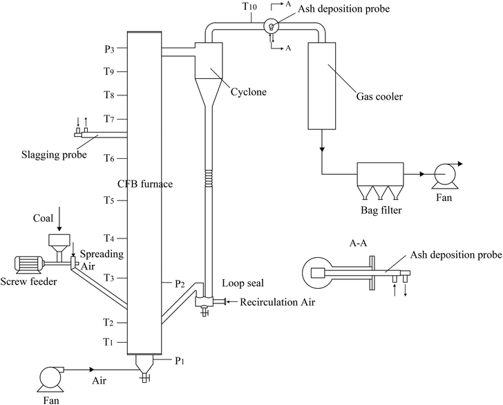
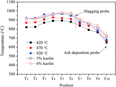
Ash deposition tests were conducted in a 30 kW CFB test system, as shown in Fig. 1. The CFB furnace is 4.8 m high with an inner diameter of 200 mm in the upper sections. Thermocouples and pressure sensors are equipped to measure the temperatures and pressures along the furnace. After exhausting from the cyclone, the flue gas passes in turn through the gas cooler, bag filter, and fan.To start up the CFB system, silica sand was added to the furnace and loop seal as the bed material. It was sieved in the size range of 0–3 mm, and its average diameter was 1.1 mm. Air was introduced into the furnace by a fan through the air distribution plate at the bottom of the furnace. The bed material was heated by heating wires until its temperature reached 550 °C. At the same time, the fuel was fed into the furnace with a screw feeder, leading to further increase in the temperature. When the bed temperature increased to the designated value, the circulation air entered to construct the circulation combustion. Finally, the relative operation parameters were carefully regulated to achieve the stable operation of the CFB system.
In the ZD coal burning tests, the bed temperature was kept at 820 °C, 870 °C, and 920 °C, while for the kaolin effect tests this temperature was 920 °C. The fluctuation range of the temperature was controlled at ±10 °C. The O2 concentration in the flue gas was measured by a ZrO oxygen analyzer. Each test lasted for 4 h. The detailed operation parameters are listed in Table 4.
| Test | I | II | III | IV | V |
| Bed temperature (°C) | 820 | 870 | 920 | 920 | 920 |
| Coal feeding rate (kg h−1) | 6.57 | 7.04 | 7.46 | 8.17 | 8.63 |
| O2 concentration in flue gas (%) | 6.7 | 6.3 | 5.9 | 5.6 | 5.1 |
| Addition ratio of kaolin (%) | 0 | 0 | 0 | 3 | 6 |
2.4 Sampling probes and analysis
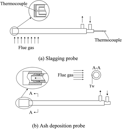
To investigate the ash slagging and deposition behavior on heating surfaces, an ash slagging probe and an ash deposition probe were designed. The slagging probe was placed in the upper part of the CFB furnace, while the ash deposition probe was installed in the convection backpass between the cyclone and gas cooler (shown in Fig. 1).Fig. 2 shows the schematics of the two probes made of jacket tubes of stainless steel. Their surface temperatures can be controlled by air flowing inside the tube. Because the aerodynamic conditions in the furnace and convection region of the backpass are not the same due to their different flow cross-sections, the outer diameters of the slagging and ash deposition probes were respectively designed according to similar Stokes number principles in industrial CFB boilers.25 Thus, there are a few differences in the structures of the two probes. The outer diameter of the slagging probe was 30 mm; a thermocouple was installed at the posterior surface of the probe to measure its surface temperature. The ash deposition probe was sealed by a probe with an outer diameter of 40 mm on the top of the outer tube. A thermocouple was inserted into the probe on the windward and was closely adjacent to the probe surface. During the tests, the surface temperatures of the two probes were controlled at approximately 400 °C. The gas temperature around the slagging probe was calculated by the average of T6 and T7, while the corresponding temperature around the ash deposition probe was determined by T10.
The ash collection efficiency (ζ) was used to evaluate the ash deposition tendency. It is defined as the mass ratio of the deposited ash particles over the fly ash particles entrained into the projected area of the probe coupon.11 The collection efficiency excluded the effect of ash concentration on the ash deposition flux, and thus facilitated the comparison of the ash deposition tendencies.
 | (1) |
At the end of each test, the fly ash was collected from the bag filter. To burn out the residual carbon, the fly ash samples were ashed at 575 °C according to ASTM standard E1755-01 before the analysis.26 The different ash deposits were carefully collected from the slagging and ash deposition probes. The bulk chemical compositions of fly ash and ash deposits were analyzed by X-ray fluorescence (XRF, HD Prime Analyzer). The mineral analysis of these samples was performed by X-ray diffraction (XRD, X'pert Pro) to identify the mineral composition. Additionally, the micro-morphologies of ash deposits were obtained by scanning electron microscopy (SEM, SIRION-100).
3 Results and discussion
3.1 Ash deposition behavior in the furnace
The macro-morphologies of ash deposits formed on the slagging probe are almost the same at different bed temperatures, as shown in Fig. 4(a). The ash deposits, referred to as slags, constitute a compacted ash layer that tightly adheres to the entire metal surface. This indicates that the slags have sintered, shrunken, or melted at relatively high temperatures, and there were strong adhesion forces between the slags and metal surfaces; it was difficult to clean-up/remove the slags using conventional soot blowers. Fig. 4(b) presents the variation trend of the collection efficiency as a function of the bed temperature. Higher temperatures lead to more slags being formed. Moreover, the slags have a reddish color, suggesting the presence of iron oxides.
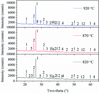
In addition, combustion temperatures also have important roles in the transformation of Ca-containing minerals. Gehlenite (Ca2(Al(AlSi)O7)) exists in fly ash at the bed temperatures of 820 °C and 870 °C, but it disappears and a new Ca-containing mineral, i.e. akermanite (Ca2Mg(Si2O7)), is observed as the temperature is further increased. The reaction of gehlenite, quartz, and periclase generates akermanite.2 These two Ca-species are fluxing materials and can enhance ash deposition.10,29
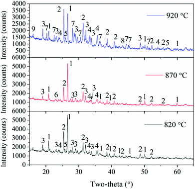
To better understand the slag formation in the furnace, Fig. 7 shows the mineral compositions of slags at different bed temperatures. At the bed temperatures of 820 °C and 870 °C, there is no obvious difference in the mineral types. Thenardite (Na2SO4) is the main existing form of Na in the slags. It has been proven that Na vaporized during combustion mainly in the form of oxides, atoms and chlorides.1 Additionally, Na2SO4 is generated from the sulphuration reaction between vaporized Na species and SO2 in the flue gas. When the flue gas flows across the slagging probe, the gaseous Na2SO4 in it will condense on the heating surface at relatively low temperatures. This may result in the increase in surface stickiness and thus, the impinging fly particles could be easily captured. Furthermore, part of the condensed Na and K species may react with aluminosilicates to form nepheline (KNa3(AlSiO4)4). As the temperature increases, glauberite (CaNa2(SO4)2) is generated because of the abundance of CaSO4 in the fly ash. The low-melting compound of Na2SO4–CaSO4 will further aggravate the slag formation.
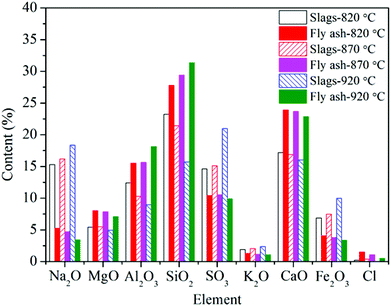
Additionally, Fe partly vaporizes under the reducing atmosphere of char particles and then reacts with oxygen when it diffuses from the char to the ambient environment during coal combustion.30 It is enriched in the slags in the form of hematite (Fe2O3). As shown in Fig. 5, the Fe2O3 content in the slags at 820 °C is the lowest, and it is only as high as 6.9%. Additionally, Fe2O3 is a fluxing mineral and the ash particles with mineral concentrations in excess of 5% Fe2O3 are easily fused.31 Thus, Fe2O3, together with the low-melting Na2SO4 and CaSO4 can form Na–Fe–Ca eutectics, which is the main reason for the formation of compacted slags because of their high content. Meanwhile, the reaction between AAEMs and Fe will take place and generate the low-melting minerals such as fenaksite (KNaFe(Si4O10)) and magnesioferrite (MgFe2O4).
3.2 Ash deposition behavior in the convection region
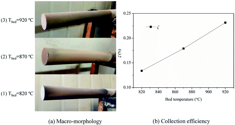
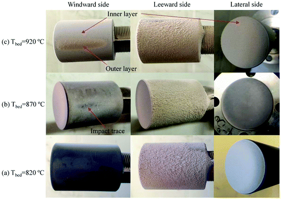
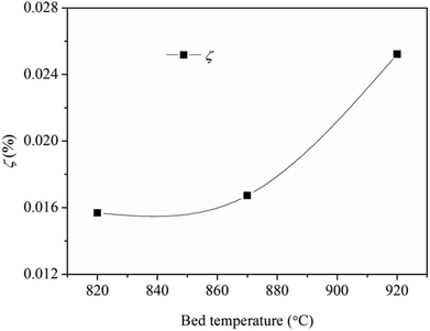
Fig. 9 shows the collection efficiency of the ash deposition probe. The collection efficiency increases as a function of the bed temperature, especially when the temperature increases from 870 °C to 920 °C. This is mainly attributed to the formation of deposited ash on the windward side.
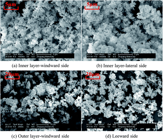
Because the macro-morphologies of deposited ash formed at 920 °C are most representative, their SEM micro-morphologies are further shown in Fig. 10. The inner layer, which is formed both on the windward and lateral sides of the probe, is composed of particles with the size of <2 μm. Moreover, they are viscous and aggregate together to form a continuous ash layer. Most deposited particles in the outer layer are larger than 10 μm, while those at the leeward are less than 10 μm. The deposited ash is composed of irregular particles almost in its entirety, and only a few spheres are found. This is ascribed to the relatively low-combustion temperature compared to that in pulverized boilers (>1100 °C). The melting phenomenon of fly ash particles does not take place in the CFB system.
In addition to the temperature, the ash deposition formation is also related to the flow field according to the macro-morphologies of deposited ash. In the specific test conditions (gas velocity: 8.9–9.9 m s−1), the flow field is a typical turbulent cross-flow field when the flue gas flows across the ash deposition probe.32 To better elucidate the ash deposition mechanism, the deposition formation is schematically shown in Fig. 11. At the initial stage, the coarse particles (>10 μm) have sufficient inertia to escape from the gas streamlines and subsequently impact on the bare surface of the windward side. However, they are easy to rebound and cannot be deposited due to their considerably huge kinetic energy.33 As the test proceeds, the inner layer is formed on the bare surface after the deposition of fine particles (<2 μm), which results from the thermophoresis. It can provide the buffering effect for the impinging particles, and their kinetic energy can be effectively dissipated. Therefore, the probability that impinging particles will stick is increased, thus leading to the formation of an outer layer. On the leeward side, turbulent eddy impaction is the controlling mechanism, which also exists in practical boilers.34 Only small particles (<10 μm) can continue to flow along with the streamlines, due to low inertia, and are then impacted and deposited on the surface.
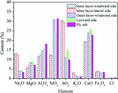
For the deposited ash on the leeward side, the contents of Na2O, CaO, MgO, and SO3, are higher compared to those in the fly ash. Especially for Ca and Mg, they play dominant roles on the formation of small particles (<10 μm), which are believed to be formed through bulk fragmentation and coalescence.36 Additionally, the chemical composition of deposited ash on the outer layer is closest to that of fly ash.
Unlike slags in the furnace, the contents of Fe in different deposited ash are almost the same as that in fly ash. On the one hand, vaporized Fe can nucleate to form ultrafine particles after combustion. On the other hand, organically bound Fe may experience fusion and coalescence on the burning char surface and contribute to the formation of particles with the size of 1–10 μm.36 Wang et al.37 carried out combustion experiments to study the effects of coal blending on the reduction of ash particles that were smaller than 10 μm. It was found that the high content of Ca can promote the liquid phase substance generated, thus leading to the formation of larger Ca–Fe–Al–Si or Fe–Al–Si particles (>10 μm). Thus, part of Fe may be transformed from fine particles to coarse particles. It has no significant influence on the formation of ash deposition in the convection region.
3.3 The effect of kaolin
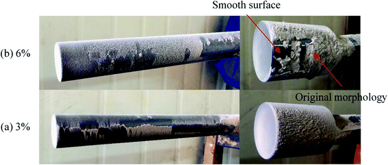
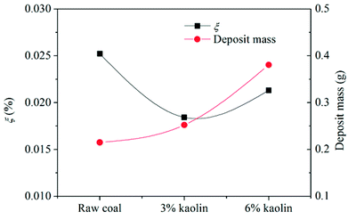
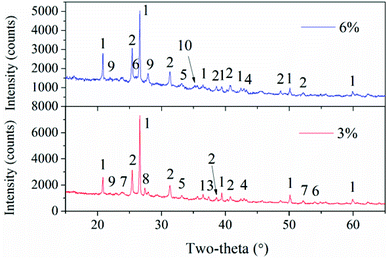
According to Fig. 14, the collection efficiency of the ash deposition probe decreases at 3% kaolin but increases when the kaolin addition ratio reaches 6%. Even so, this is below the value of burning raw coal. This indicates that the deposition tendency can be improved after adding 3% and 6% kaolin. Upon the addition of 3% kaolin, the collection efficiency reached a minimum, which mainly resulted from the disappearance of deposits on the windward side. In the tests, the Sauter mean diameter of kaolin was less than 10 μm and the number of small particles in the flue gas increased. Takuwa and Naruse also reported that the fraction of small particles with the size of 1–10 μm significantly increased after the addition of kaolin.38 These small particles are prone to deposit on the leeward side. Thus, the collection efficiency again increases as the kaolin is further increased. Wu et al.39 studied the ash transformation and deposition in a full-scale wood suspension-fired boiler with and without the addition of coal fly, which was rich in Si and Al. It was found that the ash deposition rate was increased after the addition of coal fly ash, which partly resulted from the increase of ash flux.
4 Conclusions
The ash deposition behavior of burning ZD coal with high-alkali metals in a 30 kW CFB test system was investigated. The fly ash and ash deposits in the furnace and the convection region were collected and analyzed. In addition, the effect of kaolin on the ash deposition was tested with addition ratios of 3% and 6%. The main conclusions are listed as below:(1) The slag that formed on the heating surface in the CFB furnace was a compacted ash layer that was difficult to remove. The collection efficiency of the slagging probe increased with the temperature. The melting or partial melting of slags was mainly contributed to the Na–Fe–Ca eutectics. At the bed temperature of 920 °C, the condensed Na2SO4 reacted with CaSO4 to form the low-melting compound Na2SO4–CaSO4.
(2) The deposited ash on a convection-heating surface consisted of granular particles. The layered-structure ash deposits, i.e. the layer and outer layers, on the windward side of the heating surface were only formed at the bed temperature of 920 °C but not at 870 °C and 820 °C.
(3) Ash deposition was also related to the flow field around the heating surface. The inner layer was formed by fine particles that were rich in Na2SO4 (<2 μm), due to thermophoresis. The coarse particles (>10 μm) were only deposited after the formation of the sticky inner layer, whilst small particles (<10 μm) were prone to deposit on the leeward side and were generated from the turbulent eddy impaction.
(4) Slags formed in the furnace appeared as loose ash after the addition of kaolin in the coal because of the absorption of kaolin on alkali metals. The inner layer was effectively suppressed as well. The ash deposition tendency reached its minimum at the addition of 3% kaolin. Considering the ash content in the flue ash, the net mass of deposited ash increased with the addition of kaolin.
Conflicts of interest
There is no conflicts to declare.Acknowledgements
This work was supported by the Key Project of the National Research Program of China (2015BAA04B02-09).References
- X. Wang, Z. Xu, B. Wei, L. Zhang, H. Tan, T. Yang, H. Mikulčić and N. Duić, Appl. Therm. Eng., 2015, 80, 150–159 CrossRef CAS.
- B. Wei, H. Tan, Y. Wang, X. Wang, T. Yang and R. Ruan, Appl. Therm. Eng., 2017, 119, 449–458 CrossRef CAS.
- B. Dai, F. Low, A. De Girolamo, X. Wu and L. Zhang, Energy Fuels, 2013, 27, 6198–6211 CrossRef CAS.
- H. Zhou, B. Zhou, L. Li and H. Zhang, Energy Fuels, 2014, 28, 5756–5765 CrossRef CAS.
- X. Wu, X. Zhang, K. Yan, N. Chen, J. Zhang, X. Xu, B. Dai, J. Zhang and L. Zhang, Fuel, 2016, 181, 1191–1202 CrossRef CAS.
- R. W. Bryers, Prog. Energy Combust. Sci., 1996, 22, 20–120 CrossRef.
- U. Kleinhans, R. Rück, S. Schmid, T. Haselsteiner and H. Spliethoff, Energy Fuels, 2016, 30, 9793–9800 CrossRef CAS.
- D. Lindberg, J. Niemi, M. Engblom, P. Yrjas, T. Laurén and M. Hupa, Fuel Process. Technol., 2016, 141, 285–298 CrossRef CAS.
- U. Kleinhans, C. Wieland, F. J. Frandsen and H. Spliethoff, Prog. Energy Combust. Sci., 2018, 68, 65–168 CrossRef.
- J. Li, M. Zhu, Z. Zhang, K. Zhang, G. Shen and D. Zhang, Fuel Process. Technol., 2016, 144, 155–163 CrossRef CAS.
- G. Li, S. Li, Q. Huang and Q. Yao, Fuel, 2015, 143, 430–437 CrossRef CAS.
- Y. Liu, L. Cheng, Y. Zhao, J. Ji, Q. Wang, Z. Luo and Y. Bai, Fuel Process. Technol., 2018, 169, 288–294 CrossRef CAS.
- G. Y. Li, C. A. Wang, Y. Yan, X. Jin, Y. H. Liu and D. F. Che, J. Energy Inst., 2015, 89, 48–56 CrossRef.
- J. Sandberg, C. Karlsson and R. B. Fdhila, Appl. Energy, 2011, 88, 99–110 CrossRef CAS.
- Z. Gogebakan, Y. Gogebakan, N. Selçuk and E. Selçuk, Bioresour. Technol., 2009, 100, 1033–1036 CrossRef CAS PubMed.
- P. J. van Eyk, A. Kosminski and P. J. Ashman, Energy Fuels, 2012, 26, 118–129 CrossRef CAS.
- X. Qi, G. Song, W. Song, S. Yang, Z. Yang and Q. Lyu, Energy Fuels, 2017, 31, 13239–13247 CrossRef CAS.
- G. Song, X. Qi, W. Song and S. Yang, Fuel, 2017, 205, 46–59 CrossRef CAS.
- S. Kyi and B. L. Chadwick, Fuel, 1999, 78, 845–855 CrossRef CAS.
- L. Xu, J. Liu, Y. Kang, Y. Miao, W. Ren and T. Wang, Energy Fuels, 2014, 28, 5640–5648 CrossRef CAS.
- L. Xu, Y. Kang, G. Zhang, T. Wang and T. Wu, Combust. Sci. Technol., 2015, 187, 1959–1973 CrossRef CAS.
- B. Wei, X. Wang, H. Tan, L. Zhang, Y. Wang and Z. Wang, Fuel, 2016, 181, 1224–1229 CrossRef CAS.
- Y. Wang, J. Jin, D. Liu, H. Yang and X. Kou, Fuel, 2018, 216, 697–706 CrossRef CAS.
- E. Rassk, Mineral impurities in coal combustion, Hemisphere Publishing Corporation, Washington, 1985 Search PubMed.
- G. Li, S. Li, X. Xu, Q. Huang and Q. Yao, Energy Fuels, 2014, 28, 219–227 CrossRef CAS.
- X. Zhang, H. Zhang and Y. Na, Procedia Eng., 2015, 102, 305–314 CrossRef CAS.
- J. Zhang, C. L. Han, Z. Yan, K. L. Liu, Y. Q. Xu, C. D. Sheng and W. P. Pan, Energy Fuels, 2001, 15, 786–793 CrossRef CAS.
- C. Wang, G. Li, Y. Du, Y. Yan, H. Li and D. Che, J. Energy Inst., 2018, 91, 251–261 CrossRef CAS.
- G. Kostakis, J. Hazard. Mater., 2011, 185, 1012–1018 CrossRef CAS PubMed.
- R. Ruan, H. Tan, X. Wang, Y. Li, S. Li, Z. Hu, B. Wei and T. Yang, Fuel, 2018, 211, 206–213 CrossRef CAS.
- W. Xuan, K. J. Whitty, Q. Guan, D. Bi, Z. Zhan and J. Zhang, Energy Fuels, 2015, 29, 405–421 CrossRef CAS.
- Z. Tong, M. Li, Y. He and H. Tan, Appl. Therm. Eng., 2017, 185, 2181–2193 Search PubMed.
- U. Kleinhans, C. Wieland, S. Babat, G. Scheffknecht and H. Spliethoff, Proc. Combust. Inst., 2017, 36, 2341–2350 CrossRef CAS.
- L. L. Baxter and R. W. DeSollar, Fuel, 1993, 72, 1411–1418 CrossRef CAS.
- X. P. Zeng, D. X. Yu, B. Fan, J. Q. Wu and M. H. Xu, J. China Coal Soc., 2015, 40, 2690–2695 CAS.
- X. Gao, M. U. Rahim, X. Chen and H. Wu, Fuel, 2014, 117, 825–832 CrossRef CAS.
- Q. Wang, L. Zhang, A. Sato, Y. Ninomiya and T. Yamashita, Fuel, 2008, 87, 2997–3005 CrossRef CAS.
- T. Takuwa and I. Naruse, Proc. Combust. Inst., 2007, 31, 2863–2870 CrossRef.
- H. Wu, M. S. Bashir, P. A. Jensen, B. Sander and P. Glarborg, Fuel, 2013, 113, 632–643 CrossRef CAS.
- C. Y. Chen, G. S. Lan and W. H. Tuan, Ceram. Int., 2000, 26, 715–720 CrossRef CAS.
- Z. Huang, Y. Li, D. Lu, Z. Zhou, Z. Wang, J. Zhou and K. Cen, Energy Fuels, 2013, 27, 2049–2056 CrossRef CAS.
| This journal is © The Royal Society of Chemistry 2018 |

