 Open Access Article
Activated carbon fiber/Fe3O4 composite with enhanced electromagnetic wave absorption properties
Qilong Sun *ab,
Lei Sunab,
YingYing Caiab,
Tao Jiab and
Guangyu Zhangab
aNational & Local Joint Engineering Research Center of Technical Fiber Composites for Safety and Protection, Nantong University, Nantong 226019, Jiangsu, P. R. China
bCollege of Textiles and Clothing, Nantong University, Nantong 226019, Jiangsu, P. R. China. E-mail: sunqilong001@ntu.edu.cn
First published on 15th October 2018
Abstract
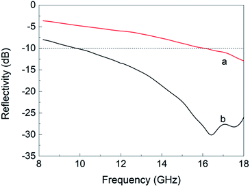
To obtain a low-density material that is capable of absorbing electromagnetic waves over a wide bandwidth, an activated carbon fiber/Fe3O4 composite material (ACF/Fe3O4) was prepared using an in situ reduction method. Scanning electron microscopy images show that Fe3O4 nanoparticles, approximately 10–40 nm in size, were spread uniformly over the surface of the ACF. The resulting composite exhibited superparamagnetic behavior at room temperature. The ability of the ACF and ACF/Fe3O4 composite to absorb electromagnetic waves over a frequency range of 8.2–18 GHz was measured using the arch method. The results showed that the maximum reflectivity of an ACF felt was −12.9 dB at 18 GHz, and the effective microwave-absorbing bandwidth (R < −10 dB) was 1.9 GHz (16.10–18 GHz). The absorption performance of the ACF was greatly enhanced by being loaded with Fe3O4 nanoparticles; the maximum reflectivity of the 2 mm layer of the ACF/Fe3O4 composite was −30.07 dB at 16.45 GHz, and the effective bandwidth (R < −10 dB) increased to 8.62 GHz (9.38–18 GHz). Coating with nano-Fe3O4 magnetic particles can effectively improve the absorption of electromagnetic waves by the ACF, and this technique therefore has great potential for application to the field of electromagnetic shielding.
Introduction
With the rapid development of electronic technology, electromagnetic interference has become the fourth major type of pollution, after water pollution, atmospheric pollution, and noise pollution, and constitutes a serious threat to human health.1–3 Meanwhile, the leakage of electromagnetic waves also affects the normal operation of electronic equipment, resulting in serious losses.4 The development of a microwave-absorbing material that is thin while having a low density, as well as having a broad, strong absorption band, would be of great significance to the improvement of the quality of human life and for the industrial production of electromagnetic protection equipment and materials.In general, magnetic particles such as Fe,5 Co,6 Ni,7 Fe3O4,8 and carbonyl iron9 particles can be used to absorb electromagnetic waves due to their highly complex permeability; however, their high densities and narrow absorption bands limit their applicability.10,11 Electromagnetic wave loss is such that the overall loss is determined by both the magnetic and electrical losses. Combining a magnetic material with a dielectric can not only reduce the weight but also achieve better microwave absorption through impedance matching. Carbon fiber is a type of dielectric-loss material with a carbon content of more than 95%. It offers the advantages of low density and a low coefficient of thermal expansion, as well as good absorbency of electromagnetic waves at high frequencies, relative to magnetic metal materials.12,13 However, not every type of carbon fiber can be used as a microwave-absorbing material; this depends on the conductivity of the carbon fiber. An excessively high electrical conductivity causes the carbon fibers to reflect electromagnetic waves, which strongly affects their ability to absorb microwaves. Therefore, only carbon fibers that have been specially treated can be used to absorb microwaves. Wu et al.14 suggested that the use of activated carbon fiber (ACF) is an effective approach to increasing electromagnetic wave absorption because of the multiple reflections and longer propagation distance inside the composite.
In the present study, we prepared a lightweight composite material, capable of absorbing electromagnetic waves over a wide bandwidth, by coating ACF with Fe3O4 magnetic particles. The Fe3O4 magnetic particles were applied using an in situ reduction method, and the reflectivities of the ACF and ACF/Fe3O4 felts over a frequency range of 8.2–18 GHz were studied using the arch method.
Experimental
Materials
Viscose fiber felt (Jiangsu Sutong Carbon Fiber Co., Ltd.), phosphoric acid (Nantong Qixiang Biotechnology Co., Ltd.), anhydrous ferric chloride (FeCl3; Shanghai Runjie Chemical Reagent Co., Ltd.), and glucose monohydrate (C6H12O6·H2O; Shanghai Runjie Chemical Reagent Co., Ltd.), all of reagent grade, were purchased and used without any further purification.Preparation of ACF felt
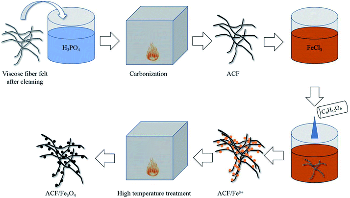
The viscose fiber felt samples were cleaned by ultrasonication in water for 30 min to remove the textile oiling agent. Phosphoric acid was employed as an activator to prepare the viscose-based ACF. The dried viscose fiber felts were soaked in phosphoric acid solution (2.0 mol L−1) for 2 h and then dried at 60 °C. The dried sample was then placed in a vacuum muffle furnace and carbonized under a nitrogen atmosphere. The carbonization temperature was 650 °C; the heating rate was 10 °C min−1, and the holding time was 1 h. This produced the ACF felt.Preparation of ACF/Fe3O4 felt
The ACF felts were immersed in saturated FeCl3 solution (1000 mL) at 60 °C for 2 h, then 15 g of glucose monohydrate was added, followed by ultrasonication for 1 h. The sample was dried at 60 °C, after which it was subjected to a further high-temperature treatment in a vacuum muffle furnace; the treatment temperature was 750 °C, the heating rate was 15 °C min−1, and the holding time was 30 min. This produced ACF/Fe3O4 felts. The preparation process is illustrated in Fig. 1.Characterization
The surface morphologies of ACF and ACF/Fe3O4 were characterized using field-emission scanning electron microscopy (FESEM; S-4800, Hitachi High-Technologies) with an acceleration voltage of 3 kV.An X-ray diffraction (XRD) analyzer (D/max-2500 PC, Rigaku) was used to analyze the phase structure of the ACF and ACF/Fe3O4. The analysis used Cu Kα radiation, a voltage and current of 40 kV and 40 mA respectively, a step length of 0.02°, and a scanning range of 10–90°.
The surface chemical compositions of the ACF and ACF/Fe3O4 were analyzed using X-ray photoelectron spectrometry (XPS; ESCALAB-250Xi, Thermo Fisher Scientific). The X-ray source was Al Kα, the vacuum level of the test system was 10−8–10−9 Pa, and the angle between the electron beam and sample was 45°.
The magnetic properties of ACF/Fe3O4 are presented as a hysteresis loop, measured using a superconducting quantum interference device-vibrating sample magnetometer (SQUID-VSM; MPMS3, Quantum Design) at room temperature.
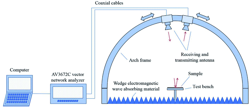
The electromagnetic wave absorption performance was investigated by the arch method. The testing apparatus is schematically illustrated in Fig. 2. The vector network analyzer connected with the receiving and transmitting antennas, one having functions of stimulating and transmitting frequency electromagnetic waves through and the other receiving the reflective signal. According to the feedback signal strength, the size of the samples was 180 × 180 mm with 2 mm thickness.
Results and discussion
Phase composition and morphology
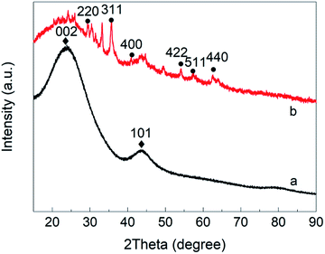
The XRD pattern for the ACF is shown in Fig. 3(a). ACF has a typical amorphous structure,15 with two strong amorphous diffraction peaks at 2θ = 23° and 2θ = 44°, corresponding to the (002) and (101) crystal planes, respectively. Fig. 3(b) shows the XRD pattern for ACF/Fe3O4. New crystals appear at 2θ = 30.42°, 35.74°, 40.28°, 43.46°, 53.94°, 57.24°, and 62.90°, which correspond, respectively, to the (220), (311), (400), (422), (511), and (400) crystal planes of the face-centered cubic Fe3O4 crystals (JCPDS no. 19-0269).16 It is noted that glucose plays an important role in Fe3O4 formation because it can decompose to reductive CO gas, which can fully reduce Fe3+ to Fe2+. This explains why no Fe2O3 signal are found in the XRD pattern. The particle size of Fe3O4 at the (311) crystal surface, calculated using the Scherrer equation, is approximately 16.18 nm, indicating that the Fe3O4 particles prepared using this method will be nano-sized.Note that there are some miscellaneous peaks, which may indicate the presence of FeOOH, FeO, Fe2C, or Fe(OH)2. FeOOH and Fe(OH)2 are likely to be the products of trace amounts of Fe3O4 undergoing acid–base reactions; FeO and Fe2C may be derived from the carbonization reactions, caused by the reaction of Fe3O4 with carbon (C) in the raw material or with the cracked gas containing carbon and oxygen.17
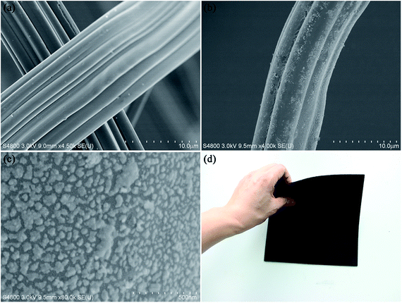
The microstructures of the ACF and ACF/Fe3O4 were characterized by FESEM. Fig. 4(a) shows a SEM image of the ACF. The surface of the ACF is relatively smooth, and there are no particles on the surface that would indicate residual impurities. Fig. 4(b) and (c) shows SEM images of ACF/Fe3O4 at different magnifications. Most of the Fe3O4 particles are distributed uniformly over the surface of the ACF. The Fe3O4 particles are irregular in shape while their sizes are within a range of 15–60 nm, which corresponds to the particle size as calculated from the XRD pattern via the Scherrer equation. Fig. 4(d) showed that the as-prepared ACF/Fe3O4 felt was easy to bend, indicative of good flexibility after the treatment.
Chemical composition
The elemental compositions and chemical states of the ACF and ACF/Fe3O4 were characterized by XPS. Fig. 5(a) shows the XPS survey spectra for the ACF and ACF/Fe3O4. There are two distinct peaks in these spectra, corresponding to C 1s and O 1s, respectively. An additional distinct peak appears in the XPS spectrum for ACF/Fe3O4, which corresponds to Fe 2p. The high-resolution Fe 2p spectrum is shown in Fig. 5(b); the two peaks at binding energies of 710.9 eV and 724.5 eV correspond to the Fe 2p3/2 and Fe 2p1/2 spin–orbit peaks, respectively, indicating the formation of Fe3O4. Fig. 5(c), (d) shows the O 1s XPS spectra for the ACF and ACF/Fe3O4 with peak-fitting curves; three peaks are visible for both the ACF and ACF/Fe3O4, at 531.2 eV, 532.3 eV, and 533.2 eV, corresponding to O–C![[double bond, length as m-dash]](https://www.rsc.org/images/entities/char_e001.gif) O, C
O, C![[double bond, length as m-dash]](https://www.rsc.org/images/entities/char_e001.gif) O, and C–O, respectively. Meanwhile, the distinct peak at 530.5 eV in the O 1s spectra of ACF/Fe3O4 is assigned to the Fe–O bonds in Fe3O4, which further demonstrates the existence of Fe3O4.
O, and C–O, respectively. Meanwhile, the distinct peak at 530.5 eV in the O 1s spectra of ACF/Fe3O4 is assigned to the Fe–O bonds in Fe3O4, which further demonstrates the existence of Fe3O4.
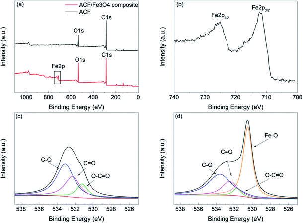 | ||
| Fig. 5 XPS spectra: (a) survey spectra of ACF and ACF/Fe3O4, (b) Fe 2p spectra of ACF/Fe3O4, and fitted O 1s spectra of (c) ACF and (d) ACF/Fe3O4. | ||
Magnetic and electromagnetic wave absorption properties
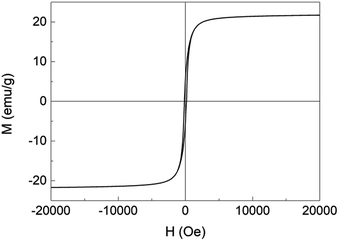
Fig. 6 shows the magnetic hysteresis loop for ACF/Fe3O4 over a range of −20![[thin space (1/6-em)]](https://www.rsc.org/images/entities/char_2009.gif) 000 to 20
000 to 20![[thin space (1/6-em)]](https://www.rsc.org/images/entities/char_2009.gif) 000 Oe at room temperature; its shape is a typical S-curve, corresponding to the superparamagnetic behavior. The magnetic properties including the saturation magnetization Ms, magnetic coercivity HC, and remanent magnetization Mr are 22 emu g−1, 114 Oe and 3.4 emu g−1, respectively. The Ms of ACF/Fe3O4 is lower than that of bulk Fe3O4 (ca. 84.5 emu g−1), which can be explained by the small size of the Fe3O4 nanoparticles and the addition of ACF, which is in good agreement with the findings of a previous study.18
000 Oe at room temperature; its shape is a typical S-curve, corresponding to the superparamagnetic behavior. The magnetic properties including the saturation magnetization Ms, magnetic coercivity HC, and remanent magnetization Mr are 22 emu g−1, 114 Oe and 3.4 emu g−1, respectively. The Ms of ACF/Fe3O4 is lower than that of bulk Fe3O4 (ca. 84.5 emu g−1), which can be explained by the small size of the Fe3O4 nanoparticles and the addition of ACF, which is in good agreement with the findings of a previous study.18
The microwave-absorbing properties of the ACF/Fe3O4 felt and ACF felt over a frequency range of 8.2–18 GHz are presented as the reflectivity R, as measured using the arch method. The arch method is a simple and practical method with which the reflectivity of microwave-absorbing materials can be accurately measured without destroying their structure.10,13 Fig. 7(a) shows the microwave absorption/reflectivity curve for ACF felt. The maximum reflectivity is −12.9 dB at 18 GHz, and the effective absorption bandwidth (R < −10 dB) is 1.9 GHz (16.10–18 GHz). Since ACF is a nonmetallic conductive fiber material with relative high resistance, it can be regarded as a harmonic oscillator in the electromagnetic field, which resonates with incident electromagnetic waves to form a dissipative current. Such generated photocurrent is finally consumed in the material system. ACFs can also be regarded as a dipole under the action of an electromagnetic field. The surface polarization of ACFs further dissipates and decays the photocurrent, converting the electromagnetic energy to other forms of energy under the action of the surrounding matrix.19 Fig. 7(b) shows the absorption–reflectivity curve of ACF/Fe3O4. The absorption properties of ACF felt are greatly enhanced after loading with Fe3O4 nanoparticles, with the maximum reflectivity reaching −30.7 dB at 16.4 GHz, and the effective absorption bandwidth (R < −10 dB) is 8.2 GHz (9.8–18 GHz). Such enhanced properties are mainly due to the unique electromagnetic properties of nano Fe3O4. The attached Fe3O4 have functions of hysteresis loss, natural resonance and exchange resonance toward electromagnetic wave, resulting in significant attenuation of electromagnetic wave. Besides, magnetic nanoparticles increases the effective contact interface to electromagnetic wave, greatly enhancing the interfacial polarization effect. Thus, the enhanced absorbing property of the composite is owing to the synergistic effect of the electric loss ACF and the magnetic loss Fe3O4.20,21
Conclusion
In summary, an ACF/Fe3O4 composite was successfully prepared using an in situ reduction method. The Fe3O4 was in the form of nanoparticles that are uniformly dispersed over the surface of the ACF and which exhibit superparamagnetism at room temperature. The maximum reflectivity of the ACF reached −12.9 dB at 18 GHz, while the effective absorption bandwidth (R < −10 dB) was 1.9 GHz. The ACF/Fe3O4 felt exhibits greatly improved microwave absorption relative to the ACF felt, with a maximum reflectivity of −30.7 dB at 16.4 GHz and an effective absorption bandwidth (R < −10 dB) of 8.2 GHz, for a thickness of 2 mm. Together, these properties indicate that ACF/Fe3O4 offers the promise of wide-ranging applicability in the fields of absorbing materials and electromagnetic shielding.Conflicts of interest
There are no conflicts to declare.Acknowledgements
This study was supported by the National Key Research and Development Program of China (2016YFB0303100), the National Science Foundation for Young Scientists of China (Grant No. 51503105), and the Graduate Innovation Project of Nantong University College of Textiles and Clothing (FZ201705).Notes and references
- E. G. Kivrak, K. K. Yurt and A. A. Kaplan, et al., Effects of electromagnetic fields exposure on the antioxidant defense system, J. Microsc. Ultrastruct., 2017, 5, 167–176 CrossRef PubMed.
- S. Kaplan, O. G. Deniz and M. E. Önger, et al., Electromagnetic Field And Brain Development, J. Chem. Neuroanat., 2016, 75(Pt B), 52–61 CrossRef PubMed.
- A. Khalil, R. T. Ali and N. A. Fattah, Radiation leakage from electromagnetic oven, J. Radiat. Res. Appl. Sci., 2015, 8(4), 483–488 CrossRef.
- P. M. Mariappan, D. R. Raghavan and S. H. E. A. Aleem, et al., Effects of electromagnetic interference on the functional usage of medical equipment by 2G/3G/4G cellular phones: a review, J. Adv. Res., 2016, 7(5), 727–738 CrossRef.
- F. Wang, Y. Sun and D. Li, et al., Microwave absorption properties of 3D cross-linked Fe/C porous nanofibers prepared by electrospinning, Carbon, 2018, 134, 264–273 CrossRef CAS.
- G. Wang, X. Li and P. Wang, et al., Microwave absorption properties of flake-shaped Co particles composites at elevated temperature (293 ∼ 673 K) in X band, J. Magn. Magn. Mater., 2018, 456, 92–97 CrossRef CAS.
- Y. Guo, S. Dong and S. Liu, et al., Fabrication of porous disk-like Ni/NiO microwave absorber and its excellent broad frequency absorption performance, J. Alloys Compd., 2017, 731, 143–149 CrossRef.
- Y. He, L. Lu and K. Sun, et al., Electromagnetic wave absorbing cement-based composite using nano-Fe3O4, magnetic fluid as absorber, Cem. Concr. Compos., 2018, 92, 1–6 CrossRef CAS.
- C. Guo, Z. Yang and S. Shen, et al., High Microwave Attenuation Performance of Planar Carbonyl Iron Particles with Orientation of Shape Anisotropy Field, J. Magn. Magn. Mater., 2018, 454, 32–38 CrossRef CAS.
- L. Liu, Y. Duan and L. Ma, et al., Microwave absorption properties of a wave-absorbing coating employing carbonyl-iron powder and carbon black, Appl. Surf. Sci., 2010, 257(3), 842–846 CrossRef CAS.
- C. Mingdong, Y. Huangzhong and J. Xiaohua, et al., Optimization on microwave absorbing properties of carbon nanotubes and magnetic oxide composite materials, Appl. Surf. Sci., 2018, 434, 1321–1326 CrossRef CAS.
- M. Gholampoor, F. Movassagh-Alanagh and H. Salimkhani, Fabrication of nano-Fe3O4, 3D structure on carbon fibers as a microwave absorber and EMI shielding composite by modified EPD method, Solid State Sci., 2017, 64, 51–61 CrossRef CAS.
- F. Qin and C. Brosseau, A review and analysis of microwave absorption in polymer composites filled with carbonaceous particles, J. Appl. Phys., 2012, 111(6), 061301-24 CrossRef.
- J. Wu and D. D. L. Chung, Increasing the electromagnetic interference shielding effectiveness of carbon fiber polymer–matrix composite by using activated carbon fibers, Carbon, 2002, 40(3), 445–447 CrossRef CAS.
- Q. Liu, H. Y. Yang and L. L. Tong, Influence of Phanerochaete chrysosporium, on degradation and preg-robbing capacity of activated carbon, Trans. Nonferrous Met. Soc. China, 2014, 24(6), 1905–1911 CrossRef CAS.
- H. P. Cong, J. J. He and Y. Lu, et al., Water-soluble magnetic-functionalized reduced graphene oxide sheets: in situ synthesis and magnetic resonance imaging applications, Small, 2010, 6(2), 169–173 CrossRef CAS PubMed.
- Y. L. He, Preparation of Magnetic Activated Carbon and Study on the Influence of Fe3O4 on pore Structure of Activated Carbon, Central South University, Hunan, 2014 Search PubMed.
- S. Zhu, J. Guo and J. Dong, et al., Sonochemical fabrication of Fe3O4 nanoparticles on reduced graphene oxide for biosensors, Ultrason. Sonochem., 2013, 20(3), 872 CrossRef CAS PubMed.
- L. I. Yong-Bo, C. L. Huang and Q. U. Fa-Zeng, et al., Research Status and Prospect of Carbon Fiber Absorbing Material, Bull. Chin. Ceram. Soc., 2015, 32(11), 3228–3231 Search PubMed.
- Y. Huang, X. Ding and S. Li, et al., Magnetic reduced graphene oxide nanocomposite as an effective electromagnetic wave absorber and its absorbing mechanism, Ceram. Int., 2016, 42(15), 17116–17122 CrossRef CAS.
- H. R. Chu, Q. Zeng and P. Chen, et al., Synthesis and electromagnetic wave absorption properties of matrimony vine-like iron oxide/reduced graphene oxide prepared by a facile method, J. Alloys Compd., 2017, 719, 296–307 CrossRef CAS.
| This journal is © The Royal Society of Chemistry 2018 |

