
 Open Access Article
 This Open Access Article is licensed under a Creative Commons Attribution-Non Commercial 3.0 Unported Licence
Hierarchical porous ZnMnO3 yolk–shell microspheres with superior lithium storage properties enabled by a unique one-step conversion mechanism†
Xiaoru Sua,
Jian Huanga,
Bangyuan Yana,
Zhouping Honga,
Siyuan Lib,
Baocheng Panga,
Yulin Luoa,
Li Fenga,
Mingjiong Zhou *a and
Yongyao Xiac
*a and
Yongyao Xiac
aSchool of Materials Science and Chemical Engineering, Ningbo University, Ningbo, Zhejiang 315211, P. R. China. E-mail: zhoumingjiong@nbu.edu.cn
bState Key Laboratory of Chemical Engineering, Institute of Pharmaceutical Engineering, College of Chemical and Biological Engineering, Zhejiang University, Hangzhou, Zhejiang 310027, P. R. China
cDepartment of Chemistry, Fudan University, Shanghai, 200433, P. R. China
First published on 6th September 2018
Abstract
ZnMnO3 has attracted enormous attention as a novel anode material for rechargeable lithium-ion batteries due to its high theoretical capacity. However, it suffers from capacity fading because of the large volumetric change during cycling. Here, porous ZnMnO3 yolk–shell microspheres are developed through a facile and scalable synthesis approach. This ZnMnO3 can effectively accommodate the large volume change upon cycling, leading to an excellent cycling stability. When applying this ZnMnO3 as the anode in lithium-ion batteries, it shows a remarkable reversible capacity (400 mA h g−1 at a current density of 400 mA g−1 and 200 mA h g−1 at 6400 mA g−1) and excellent cycling performance (540 mA h g−1 after 300 cycles at 400 mA g−1) due to its unique structure. Furthermore, a novel conversion reaction mechanism of the ZnMnO3 is revealed: ZnMnO3 is first converted into intermediate phases of ZnO and MnO, after which MnO is further reduced to metallic Mn while ZnO remains stable, avoiding the serious pulverization of the electrode brought about by lithiation of ZnO.
1. Introduction
The development of power-intensive facilities such as large electric grids and electrical vehicles urges development of rechargeable lithium-ion batteries (LIBs) with high-energy density.1–5 However, conventional graphite anodes utilized in LIBs offer a low theoretical capacity of 372 mA h g−1, which is far from satisfying the ever-increasing demand. A significant advance in the field comes with the discovery of materials that operate via a conversion reaction.6,7 Transition metal compounds MxXy (M = Fe, Co, Ni, Cu, Zn, Mn, etc.; X = O, F, S, etc.) have attracted considerable interest as electrode materials owing to their high theoretical capacities.8 In these MxXy materials, transition metal oxides (MxOy, where M is Co, Ni, Cu or Fe) used as anode materials can achieve the highest capacities by utilizing all the possible oxidation states of a compound during the redox process.9 They can realize the highest capacity via the reversible conversion process through the following reaction scheme:10| MxOy + 2yLi+ ↔ xM + yLi2O | (1) |
Among these unary metal oxides, zinc oxide and manganese oxide attract extensive attention due to their great superiorities such as low cost, low charge–discharge potential and eco-friendliness.10–12 Up to now, various strategies have been developed to improve the lithium ion storage performance of zinc oxide and manganese oxide anodes.13–15 However, compared to these two unary metal oxides, crystalline ZnMnO3 shows better electrochemical performance than that of ZnO and MnO2, owing to the inner atomic synergetic effect between ZnO and MnO2 components.10 Unfortunately, ZnMnO3 also suffers from a significant capacity fading during cycling, which leads to the limit of the commercial applications. Many efforts have been made to overcome these problems and improve the performance of ZnMnO3, such as the synthesis of ZnMnO3–carbon composites and ZnMnO3 nanotube.16,17 However, such approaches still have several critical issues such as complicated synthetic processes and relatively high cost for commercialization.10,17 According to the reported literatures,18–25 the yolk–shell structure can significantly buffer the volume changes during the charge/discharge process, which is helpful for the improvement of cycling stability. Meanwhile, the nano-size units shorten the diffusion path of lithium ions and increase the reaction sites for lithium intercalation/deintercalation, which facilitates the improvement of rate capability.26–28 Thus, developing yolk–shell architecture with nano-sized particles as building blocks can combine the advantages of nano- and micro-structures, which is particularly important for achieving good rate capability and cycling stability. Herein, we report the synthesis of porous ZnMnO3 yolk–shell microspheres composed of nano-sized primary particles interconnected to form secondary micro-sized spheres, and use as high-performance anodes. By inheriting the advantages of the yolk–shell spheres formed by nano-sized particles, as-designed ZnMnO3 can effectively accommodate the large volume change upon lithiation/delithiation and assist in the formation of stable solid electrolyte interphase (SEI) layer, resulting in great electrochemical performance with high capacity, excellent cycling stability and good rate capability. Moreover, to understand the essence of the reaction, the conversion reaction mechanism of ZnMnO3 was also studied in this paper.
2. Experimental section
2.1. Synthesis of ZnMnO3 yolk–shell microspheres
The precursors of ZnMnO3 spheres started from dissolving the Zn(CH3COO)2·2H2O (Aladdin, 98.0%) and Mn(CH3COO)2·4H2O (Aladdin, 99.0%) into the polyvinyl pyrrolidone (PVP, Mw ∼ 1![[thin space (1/6-em)]](https://www.rsc.org/images/entities/char_2009.gif) 300000) (Sigma Aldrich) ethylene glycol (EG) (Aladdin) solution, which was a certain amount of PVP dissolved in EG as a soft template. In a typical synthesis, 1 mmol Zn(CH3COO)2·2H2O and 1 mmol Mn(CH3COO)2·4H2O were injected into the PVP–EG solution with vigorous stirring at 300 rpm for 120 min. The solution was then refluxed at 170 °C for 90 min in an oil bath. During the reaction, the solution gradually turned into a light purple color. Subsequently, the precursors of ZnMnO3 spheres with light purple was obtained by centrifugal separation, as well as washed with ethyl alcohol for several times, and then dried at 100 °C under vacuum for 12 h. Finally, the precursors were annealed at 500 °C for 4 h under air with a heating rate of 1 °C min−1, and then ZnMnO3 yolk–shell microspheres were obtained. All chemicals were used without further purification.
300000) (Sigma Aldrich) ethylene glycol (EG) (Aladdin) solution, which was a certain amount of PVP dissolved in EG as a soft template. In a typical synthesis, 1 mmol Zn(CH3COO)2·2H2O and 1 mmol Mn(CH3COO)2·4H2O were injected into the PVP–EG solution with vigorous stirring at 300 rpm for 120 min. The solution was then refluxed at 170 °C for 90 min in an oil bath. During the reaction, the solution gradually turned into a light purple color. Subsequently, the precursors of ZnMnO3 spheres with light purple was obtained by centrifugal separation, as well as washed with ethyl alcohol for several times, and then dried at 100 °C under vacuum for 12 h. Finally, the precursors were annealed at 500 °C for 4 h under air with a heating rate of 1 °C min−1, and then ZnMnO3 yolk–shell microspheres were obtained. All chemicals were used without further purification.
2.2. Material characterization
The phase composition of the as-prepared ZnMnO3 samples was characterized by powder X-ray diffraction (XRD). The XRD patterns were collected on an X-ray diffractometer (Bruker D8 Advance, Germany) with Cu-Kα radiation (λ = 0.1540 nm) at 40 kV, 40 mA from 10° to 70° with 0.02 per step. The morphology and particle size of samples were performed using scanning electron microscopy (SEM, Hitachi S-4800, 15 kV) with energy dispersive X-ray spectroscopy (EDS), transmission electron microscopy (TEM, JEOL EM-2010F). The Brunauer–Emmett–Teller (BET, Micromeritics VacPrep 061) method was utilized to determine the specific surface area of the synthesized samples at 77 K in nitrogen atmosphere at 150 °C for 6 h to remove the adsorbed water molecules. To analyze the structure evolution during cycling, the cycled electrodes at different states were also explored by XRD, at 2θ range of 10–70° with 0.02 per step. For these XRD samples, the working electrodes were prepared by using the ZnMnO3, conductive carbon and PTFE-binder (60:30:10 by wt%). The surface compositions were analyzed by X-ray photoelectron spectroscopy (XPS, ThermoFisher Scientific ESCALAB 250Xi) with a beam of monochromatic aluminum X-ray source.
2.3. Electrochemical measurements
The electrochemical measurements were carried out using CR2032 coin-type half-cells. Slurries were prepared containing 60 wt% active material (the as-prepared ZnMnO3 samples), 30 wt% Super P and 10 wt% PVDF in N-methyl-2-pyrrolidone. The slurries were coated onto copper foil, dried at 100 °C for 12 h in a vacuum oven, and cut into 1/2 in. diameter electrodes for testing. The amount of material on the Cu foil was 1.5–2 mg cm−2, thus the active material loading was calculated to be ca. 0.9–1.2 mg cm−2. Coin cells were assembled in Ar-filled glove box, using lithium metal as the counter electrode, Celgard 2400 as the separator, and 1 M LiPF6 in a mixture of ethylene carbonate (EC) and dimethyl carbonate (DMC) (1:1 by volume) as the electrolyte (3015A, Guo Tai Hua Long Company). Galvanostatic charge and discharge tests were carried out at different constant current densities between 0.01 and 3.0 V using a LAND battery system (Wuhan, China). Cyclic voltammetry (CV) was performed at a CHI-660E workstation with voltage range of 0.01–3.0 V at a scan rate of 0.1 mV s−1. Electrochemical impedance spectra (EIS) of the cells were collected by a CHI-660E workstation, using an alternating current with an amplitude of 5 mV in the frequency range of 0.01–100 kHz.
3. Results and discussion
Fig. 1 describes the schematic illustration of the formation process of ZnMnO3 yolk–shell microspheres. In the first step, the amount of Zn(CH3COO)2·2H2O and Mn(CH3COO)2·4H2O are dissolved into the PVP–EG solution, which acts as the soft template. Subsequently, the solution is then refluxed and the reaction happens to form ZnMn-glycolate precursor.29 At last, the obtained precursor are calcined at 500 °C for 4 h in tubular furnace, giving rise to the formation of yolk–shell ZnMnO3 microspheres as well as copying the morphology of the precursor.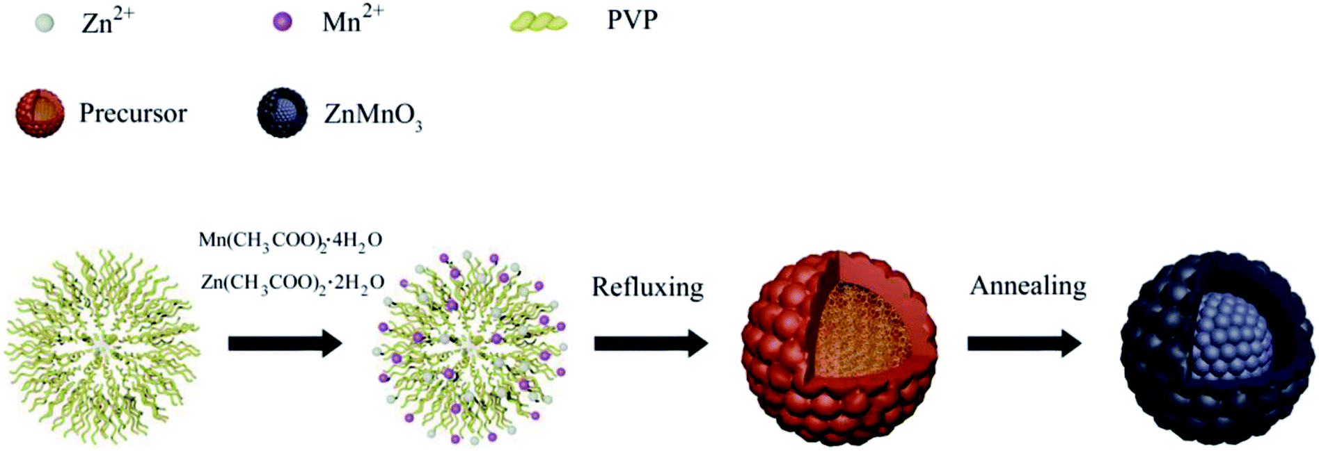 | ||
| Fig. 1 Schematic illustration of the formation process of ZnMnO3 yolk–shell spheres. | ||
Fig. 2 shows the powder X-ray diffraction (XRD) patterns of both ZnMn-glycolate precursor and as-prepared ZnMnO3 product. All diffraction peaks can be indexed to the cubic ZnMnO3 phase (JCPDS card no. 19-1461), and no impurity phase is detected, indicating the formation of single ZnMnO3 product. The sharp diffraction peaks suggest that the obtained ZnMnO3 particles are highly crystalline. The morphology and structure of the products were characterized by scanning electron microscopy (SEM) and transmission electron microscope (TEM), as shown in Fig. 3. The SEM image in Fig. 3a shows that the ZnMn-glycolate precursors display uniform spheres with diameters ranging from 1 to 3 μm. After annealing at 500 °C for 4 h, the morphology can be well retained as high quality spheres compared with that of the ZnMn-glycolate precursors (Fig. 3b). Moreover, the porosity of ZnMnO3 microspheres could be achieved due to the release of CO2 gas from ZnMn-glycolate precursors (Fig. 3c).30
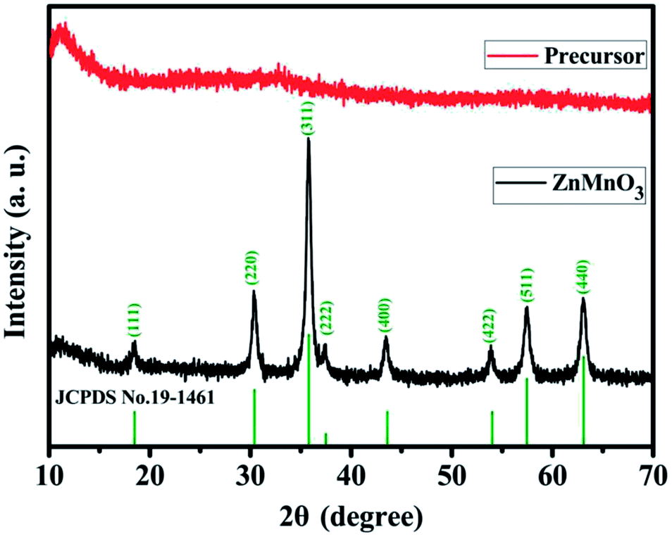 | ||
| Fig. 2 XRD patterns of the as-synthesized ZnMn-glycolate precursor and ZnMnO3 product annealed at 500 °C in air for 4 h with a heating rate of 1 °C min−1. Vertical lines represent the corresponding standard pattern of JCPDS no. 19-1461 for the ZnMnO3 phase. | ||
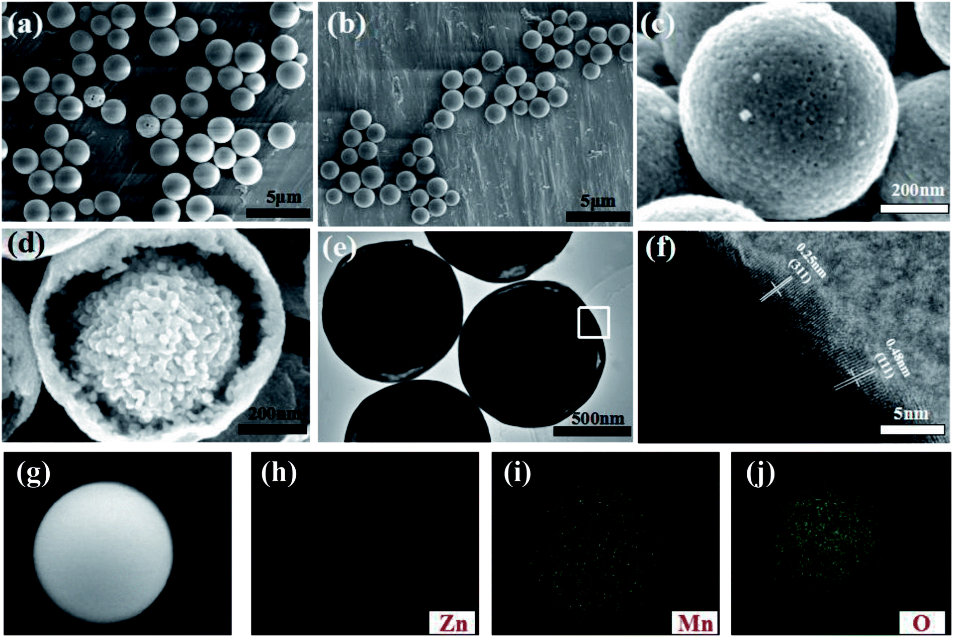 | ||
| Fig. 3 (a) SEM image of ZnMn-glycolate precursor microspheres; (b–d and g) SEM images of ZnMnO3 microspheres; (e) TEM image and (f) HRTEM image of ZnMnO3 microspheres; (h–j) Zn, Mn and O element mapping of ZnMnO3 microspheres. | ||
Nitrogen isothermal absorption–desorption measurements were performed to determine the Brunauer–Emmett–Teller (BET) surface area and the porosity of the ZnMnO3 microspheres at 77.3 K. As can be seen, the isotherm curve reveals a typical type IV with a hysteresis loop at relative pressure of 0.76–1.0 in Fig. S1,† representing the mesoporous structure of ZnMnO3 microspheres. Interestingly, the ZnMnO3 microspheres possess a nano-porous feature with a narrow pore size distribution at around 16 nm, which could be derived from the controlled gas release during the annealing process (Fig. S2†). Meanwhile, the BET surface area of ZnMnO3 microspheres is about 34.0 m2 g−1. From a cracked sample shown in Fig. 3d (also see Fig. S3† for broken spheres), the inner core can be clearly observed, indicating the yolk–shell structure of ZnMnO3 microspheres. High Resolution Transmission Electron Microscopy (HRTEM) studies (Fig. 3e) further provide an evidence for the yolk–shell structure of the microspheres. The image clearly displays the lattice fringes of (311) and (111) crystal faces with interplanar distances of 0.25 nm and 0.48 nm, respectively (Fig. 3f). The elemental mapping analysis techniques were used to analyze Zn, Mn and O elements within the whole sphere framework (Fig. 3i–k) and find that all the elements distribute homogeneously in the ZnMnO3 microsphere.
The electrochemical properties of ZnMnO3 yolk–shell microspheres were examined by CR2032 coin cells using lithium metal as a counter electrode, as shown in Fig. 4. Fig. 4a shows the charge–discharge curves of ZnMnO3 microspheres for first three cycles at a current density of 400 mA g−1. The initial discharge and charge capacities are 1150 and 624 mA h g−1, respectively, which correspond to an initial coulombic efficiency of 54.3%. From the second cycle, the charge and discharge reactions proceed reversibly with small capacity loss. In addition, it can be observed from Fig. 4a that the charge/discharge process consists of two main steps. During the discharge process, a small plateau at ∼1.5 V is detected, and the second plateau is found at ∼0.5 V, followed by a long slope until cutoff voltage. However, these two plateaus almost disappear during the charge process. To further verify the electrochemical reaction of ZnMnO3, CV analysis was performed in voltage range of 0.01–3.0 V at the scan rate of 0.1 mV s−1 (Fig. 4b). During the first cathodic scan, the broad peak centered at 1.5 V, which disappears in the following scans, should be caused by the formation of SEI on the surface of ZnMnO3 because of the irreversible decomposition of the electrolyte.31 The weak peak at 0.7 V can be ascribed to the reduction of Mn(IV) to Mn(II) while the sharp peak at 0.5 V is assigned to the reduction of Mn(II) to metallic Mn.17 However, from the second cathodic scan, these two peaks become smaller and shift to high voltages of 1.1 and 0.6 V, respectively. Since the first anodic scan, the CV profiles achieved in the subsequent cycles are duplicated time after time according to reaction, and two anodic peaks are observed at around 1.2 and 1.5 V, associating with the oxidation of Mn to Mn(II) and Mn(II) to Mn(IV), respectively. However, there are no obvious peaks corresponding to valence change of element Zn in ZnMnO3 materials, meaning that Zn(II) almost remains stable during whole electrochemical reaction, which will be demonstrated by ex situ XRD and XPS later.
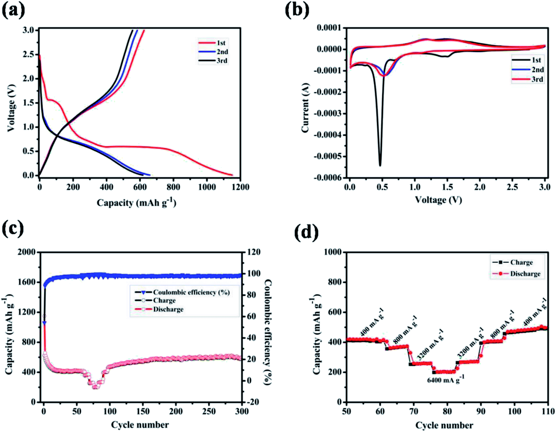 | ||
| Fig. 4 (a) The first three charge–discharge profiles at a current density of 400 mA g−1 in the range of 0.01–3.0 V (vs. Li+/Li); (b) cyclic voltammetric curves at a scan rate of 0.1 mV s−1 in voltage rang of 0.01–3.0 V (vs. Li+/Li); (c) cycling life and the corresponding coulombic efficiency at a current density of 400 mA g−1; (d) rate capability at various current densities from 400 to 6400 mA g−1. | ||
Fig. 4c shows the cycling performance of ZnMnO3 microspheres at a constant current of 400 mA g−1, together with the rate performance at the stable stage. The specific capacity decreases gradually in the first 20 cycles, and then slightly increases to ∼540 mA h g−1 up to 300 cycles. Moreover, this novel ZnMnO3 shows an initial coulombic efficiency of ∼54.3%, which quickly increases to 98% after several cycles and remains as nearly 100% thereafter. However, it is pointed out that the electrochemical properties of as-prepared ZnMnO3 microspheres become poor when the active material loading of electrode is 2.3 mg cm−2 or the mass ratio of conductive carbon decreases by 10 wt%, as shown in Fig. S4.† Compared to the reported ZnMnO3 with other morphologies (Table 1 in ESI†),5,10 the yolk–shell ZnMnO3 microspheres in this research exhibit higher capacity retention even after 300 cycles. In additional to high capacity and excellent cyclability, the rate capability of ZnMnO3 microspheres was also investigated. After cycling for 60 cycles at a current density of 400 mA g−1, the same cell was then tested at various current densities from 400 to 6400 mA g−1. As shown in Fig. 4d (the enlarged part of Fig. 4c), with the current densities increase from 400 mA g−1 to 6400 mA g−1, seven cycles are recorded for each stepwise increment. When the current density was 400 mA g−1, the ZnMnO3 electrode shows a reversible capacity of ∼400 mA h g−1. Although the capacity gradually decreases with the current density increase, the ZnMnO3 still can deliver a capacity of ∼200 mA h g−1 at the high current density of 6400 mA g−1. After the high-rate charge/discharge cycling, the current density was gradually stepwise to 400 mA g−1. The much improved performance of the as-synthesized ZnMnO3 microspheres could be ascribed to their unique structure. Specifically, it is able to provide shorter diffusion length for Li ions because of the primary nanoparticles with small particle size distributed in the ZnMnO3 microspheres. More importantly, the highly mesoporous structure of ZnMnO3 microsphere ensures penetration of liquid electrolyte and the unique yolk–shell architecture could effectively accommodate the volume expansion during the repeated Li+ insertion/extraction processes, thus forming a relatively stable SEI layer on the ZnMnO3 spheres, which renders an excellent cycling stability.
To better understand the reason for the cycle performance of ZnMnO3 microspheres, electrochemical impedance spectroscopy (EIS) was conducted on the ZnMnO3 electrodes before and after cycling. The corresponding Nyquist plots and equivalent circuit are presented in Fig. 5a and b. Obviously, all EIS spectra of ZnMnO3 electrodes consist of a small intercept at high frequency, a semicircle at the high-medium frequency and a sloping line at the low frequency before cycling and after 10 and 100 cycles. The small intercept corresponds to the resistance of the cells (R1). The semicircle is mainly associated with the charge transfer resistance at the electrode/electrolyte interface (Rct) and the double-layer capacitance between electrolyte and electrode (CPE1). The straight line in low frequency is ascribed to the Warburg impedance (Ws, relating to Li+ diffusion within electrode).32,33 Comparison of EIS curves indicate that the ZnMnO3 electrode displays negligible variance during the whole 100 cycles and also implies a relatively stable SEI formed on the surface of ZnMnO3 microspheres. The observation from SEM images also agrees well with the suggestion of EIS measurements. The surface morphology of the ZnMnO3 electrodes before cycling and after 10 and 100 cycles is presented in Fig. 5c–e, respectively. Compared with the pristine electrode (Fig. 5c), there are no obvious morphology change for the ZnMnO3 electrodes after cycling, and only a thin SEI layer can be seen after 100 cycles, which further demonstrate that the mechanical strain and the resulting cracking evolution in electrodes can be well relieved by using the unique yolk–shell architecture of ZnMnO3 microspheres.
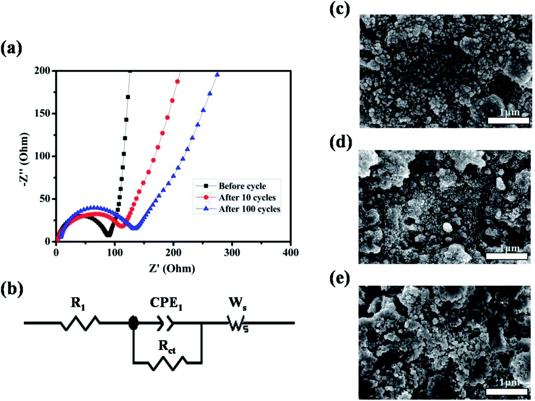 | ||
| Fig. 5 (a) EIS spectra of Li-ion cells using ZnMnO3 electrodes before cycle and after 10 and 100 cycles, respectively; (b) the corresponding equivalent circuit model with the following variables: R1 = series resistance, CPE1 = constant phase element, Rct = charge-transfer resistance, Ws = Warburg impedance. (c–e) ZnMnO3 electrodes before cycle and after 10 and 100 cycles, respectively. | ||
From the point of application, ZnMnO3 used as active material of the anode in rechargeable Li-ion batteries should be reversible during the charge/discharge process. To trace the crystal structure evolution of the ZnMnO3 during the cycling, ex situ XRD was performed on the cycled electrodes. The cycled samples at different states in the first charge/discharge process were studied, as shown in Fig. 6. All the XRD patterns show a sharp diffraction signal at 18° in accordance with the peak of PTFE,34,35 which is overlapped with the phase of (111). With the increase of discharge depth, the characteristic peaks of (220), (311), (422) and (511) become smaller and almost disappear after full discharge. In contrast, the phase of (222) increases with the discharge depth. This phenomenon suggests that the structure of ZnMnO3 is damaged during the lithiation process. However, it is clear that all the characteristic diffraction peaks of ZnMnO3 are found in XRD curve after charge up to 3.0 V. This observation indicates that the inserted Li ions are almost fully extracted from the electrode and ZnMnO3 could be restored at the end of charging. Upon closer comparison, the XRD pattern of the fully charged electrode exhibits some change from the pristine one. All of the reflections become broader and weaker, indicating that the crystalline phase tends to deteriorate, perhaps due to the formation of small particles during cycling. Therefore, it can be concluded that ZnMnO3 anode is able to cycle reversibly while the structural change presumably occurs during operating process.
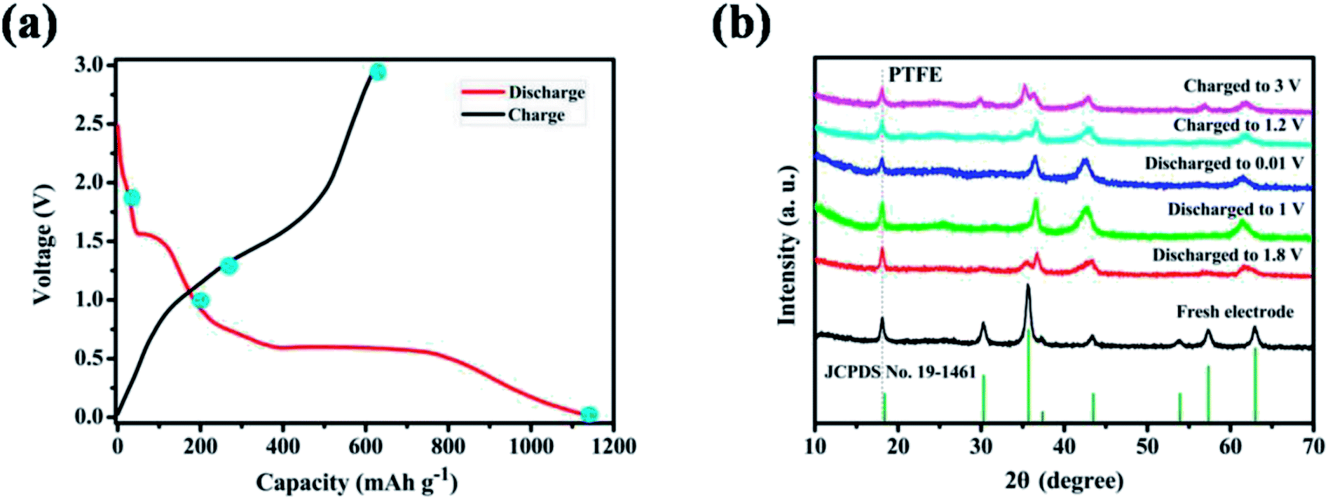 | ||
| Fig. 6 (a) The initial charge–discharge profiles at a current density of 400 mA g−1 in the range of 0.01–3.0 V (vs. Li+/Li); (b) XRD patterns of ZnMnO3 anodes at various charged/discharged states. | ||
Oxidation state of the corresponding transition metal ions in the ZnMnO3 microspheres were analyzed with XPS to further identify the detailed electrochemical mechanism of ZnMnO3 during the cycling (Fig. 7). As shown in Fig. 7a, the Zn 2p XPS spectrum after discharge or charge is quite similar to that of the pristine electrode. All of them exhibit two peaks with binding energies of around 1044.3 eV and 1021.2 eV, which can be assigned to the Zn 2p1/2 and Zn 2p3/2, respectively, suggesting the valance state of Zn(II).36–38 This result is according with the observation of CV curves that the Zn(II) in ZnMnO3 does not participate in electrochemical reactions during repeated charge/discharging process, which is different from the other Zn-containing anode materials that eventually formed the product of lithium–zinc alloy. In contrast, the Mn 2p XPS spectrum after cycling is obviously different from that of the pristine electrode (Fig. 7b). There are two major peaks with binding energies of 653.9 eV and 642.6 eV, corresponding to the Mn 2p3/2 and Mn 2p1/2, respectively.16,39,40 However, the intensities of these peaks are weakened to almost invisible when being discharged to 0.01 V, suggesting that Mn(IV) is finally reduced to metallic Mn in the composite after lithiation. After being charged to 3.0 V, these two characteristic peaks of Mn 2p3/2 and Mn 2p1/2 can still be found, which show the oxidation of metallic Mn to Mn(IV). According to the reported literature,41 the typical O 1s peak in the surface can be consistently fitted by three nearly Gaussian, centered at 530.15 ± 0.15 eV, 531.25 ± 0.20 eV and 532.40 ± 0.15 eV, respectively, which represent the three states of oxygen. Hence, as shown in Fig. 7c–e, the typical O 1s spectra can be consistently fitted into three nearly Gaussian in all the electrodes before and after cycling, centering at ∼530.1 eV, ∼531.4 eV, and ∼532.1 eV, respectively.41–43 The high binding energy component located at 532.1 eV is attributed to the presence of organic compounds, while the medium binding energy component centered at 531.4 eV is associated with the oxygen deficient regions within the matrix of ZnMnO3. The component on the low binding energy side of the O 1s spectra at 530.1 eV is corresponding to the O2− ions surrounded by metal atoms with their full complement of nearest neighbor O2− ions. Obviously, the intensity of O 1s spectra at 530.1 eV decreases after cycling compared with that of fresh sample, which proves a decrease in the amount of metal–oxygen bond. By contrast, the intensity of O 1s spectra at 531.4 eV increases after cycling, probably due to the variations in the concentration of oxygen vacancies.41 Combined XRD and XPS studies, the charge and discharge reaction of the metal oxide ZnMnO3 can be expressed as follow:
| ZnMnO3 + 4Li+ + 4e− ↔ ZnO + Mn + 2Li2O | (2) |
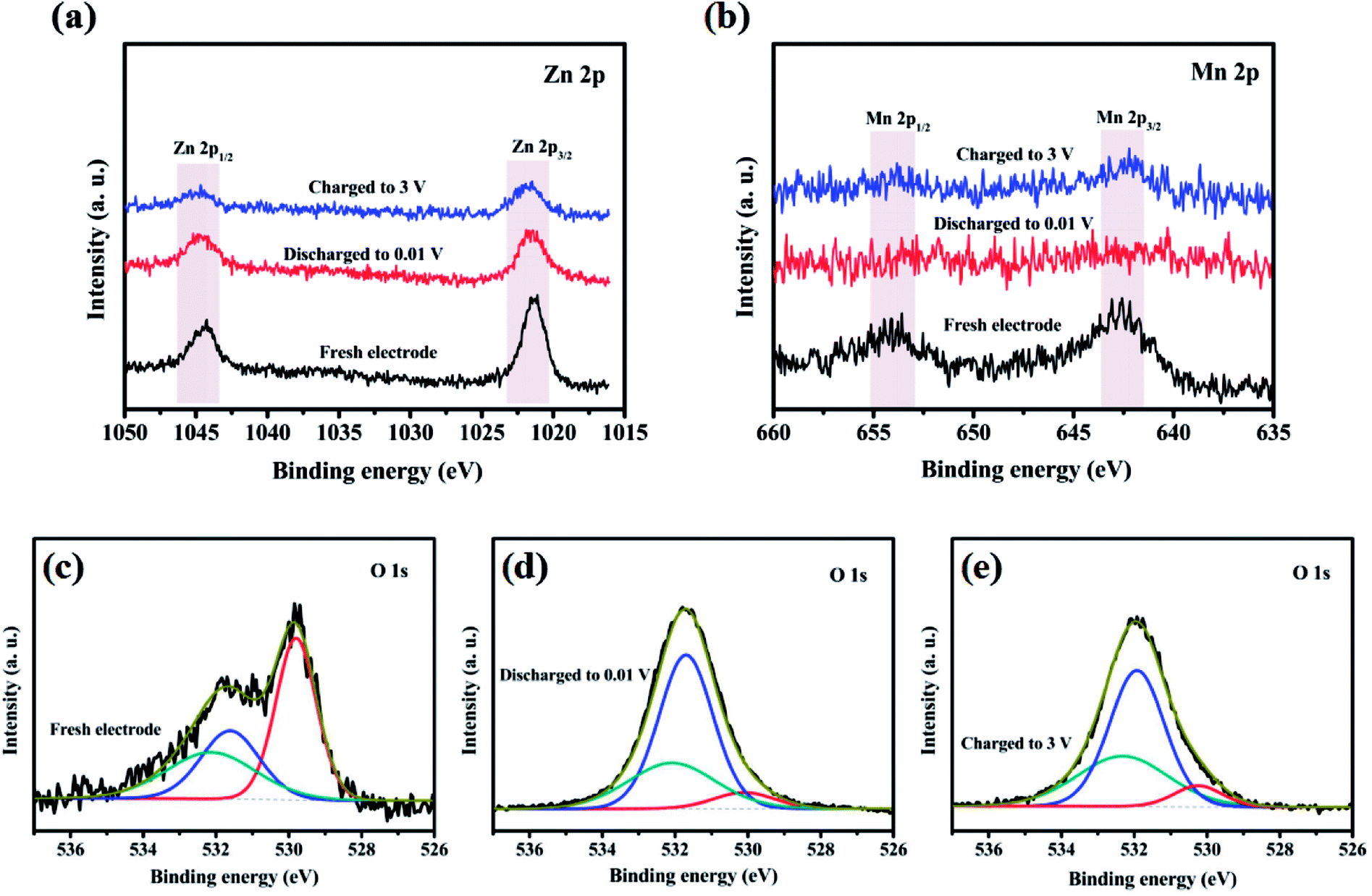 | ||
| Fig. 7 XPS spectra of (a) Zn 2p, (b) Mn 2p and (c–e) O 1s in ZnMnO3 microspheres at various charged/discharged states in the initial cycle. | ||
The capacity of ZnMnO3 anode is supposed to be contributed by the oxidation/reduction between Mn(IV) and metallic Mn in ZnMnO3 during cycling. Meanwhile, Zn(II) remains unchanged in the form of ZnO, which avoids the further pulverization of electrode due to the large expansion when ZnO lithiated. The stability of as-formed products as well as unique yolk–shell structure render the satisfied special capacity and high capacity retention for ZnMnO3 anode.
4. Conclusions
In summary, we have developed unique ZnMnO3 yolk–shell microspheres synthesized by a facile route of initial solution synthesis and subsequent annealing. By the merit of the yolk–shell structure, this kind of ZnMnO3 can effectively accommodate the large volume change upon cycling and assist the formation of stable SEI layers, resulting in a high capacity, excellent cycling stability and good rate capability. Furthermore, the combination of XRD and XPS reveals that ZnMnO3 can be restored after cycling and the capacity is contributed by the reduction/oxidation of Mn(IV) and metallic Mn. On account of the facile solution synthesis approach and the eco-friendliness and low-cost qualities, this novel multi-component functional oxide has a great potential to be used for high-capacity anode in next generation LIBs.Conflicts of interest
We declare that we do not have any commercial or associative interest that represents a conflict of interest in connection with the work submitted.Acknowledgements
This work was financially supported by the National Natural Science Foundation of China (21606135), the Science Technology Department of Zhejiang Province (2017C31086). This work was also sponsored by K. C. Wong Magna Fund in Ningbo University.References
- X. Zhu, F. Zhang, L. Zhang, L. Zhang, Y. Song, T. Jiang, S. Sayed, C. Lu, X. Wang and J. Sun, Adv. Funct. Mater., 2018, 28, 1–12 Search PubMed.
- D. Larcher and J. M. Tarascon, Nat. Chem., 2015, 7, 19–29 CrossRef PubMed.
- B. Liu, P. Soares, C. Checkles, Y. Zhao and G. Yu, Nano Lett., 2013, 13, 3414–3419 CrossRef PubMed.
- J. M. Tarascon and M. Armand, Nature, 2001, 414, 359–367 CrossRef PubMed.
- Y. Tian, Z. Chen, W. Tang, Z. Yang, W. Zhang, S. Li, K. Wang, Y. Sun, Q. Xia and B. Guo, J. Alloys Compd., 2017, 720, 376–382 CrossRef.
- M. V. Reddy, G. V. Subba Rao and B. V. Chowdari, Chem. Rev., 2013, 113, 5364–5457 CrossRef PubMed.
- J. Reed and G. Ceder, Chem. Rev., 2004, 104, 4513–4533 CrossRef PubMed.
- F. Cheng, J. Liang, Z. Tao and J. Chen, Adv. Mater., 2011, 23, 1695–1715 CrossRef PubMed.
- M. Keppeler and M. Srinivasan, ChemElectroChem, 2017, 4, 2727–2754 CrossRef.
- X. Liu, C. Zhao, H. Zhang and Q. Shen, Electrochim. Acta, 2015, 151, 56–62 CrossRef.
- C. Wang, L. Yin, X. Dong and Y. Qi, ACS Appl. Mater. Interfaces, 2012, 4, 1636–1642 CrossRef PubMed.
- Y. Deng, Z. Li, Z. Shi, H. Xu, F. Peng and G. Chen, RSC Adv., 2012, 2, 4645–4647 RSC.
- Z. D. Huang, Z. Gong, Q. Kang, Y. Fang, X. S. Yang, R. Liu, X. Lin, X. Feng, Y. Ma and D. Wang, Mater. Chem. Front., 2017, 1, 1975–1981 RSC.
- L. Wang, G. Zhang, Q. Liu and H. Duan, Mater. Chem. Front., 2018, 2, 1414–1435 RSC.
- K. Cao, T. Jin, L. Yang and L. Jiao, Mater. Chem. Front., 2017, 1, 2213–2242 RSC.
- F. Geng, A. Yuan and J. Xu, Electrochim. Acta, 2016, 216, 376–385 CrossRef.
- H. Chen, L. X. Ding, K. Xiao, S. Dai, S. Wang and H. Wang, J. Mater. Chem. A, 2016, 4, 16318–16323 RSC.
- L. F. Cui, Y. Yang, C. M. Hsu and Y. Cui, Nano Lett., 2009, 9, 3370–3374 CrossRef PubMed.
- Z. Jun, C. Jiajia, Z. Chenglong, Q. Hang, Z. Mingsen and D. Quanfeng, J. Mater. Chem. A, 2014, 2, 6343–6347 RSC.
- H. Liu, G. Wang, J. Wang and D. Wexler, Electrochem. Commun., 2008, 10, 1879–1882 CrossRef.
- H. Ren, R. Yu, J. Wang, Q. Jin, M. Yang, D. Mao, D. Kisailus, H. Zhao and D. Wang, Nano Lett., 2014, 14, 6679–6684 CrossRef PubMed.
- S. Xu, C. M. Hessel, H. Ren, R. Yu, Q. Jin, M. Yang, H. Zhao and D. Wang, Energy Environ. Sci., 2014, 7, 632–637 RSC.
- J. Wang, H. Tang, L. Zhang, H. Ren, R. Yu, Q. Jin, J. Qi, D. Mao, M. Yang and Y. Wang, Nat. Energy, 2016, 1, 16050–16058 CrossRef.
- D. Li, X. Zhao, R. Yu, B. Wang, H. Wang and D. Wang, Inorg. Chem. Front., 2018, 5, 535–540 RSC.
- J. Wang, H. Tang, H. Wang, R. Yu and D. Wang, Mater. Chem. Front., 2017, 1, 414–430 RSC.
- Y. Deng, S. Tang, Q. Zhang, Z. Shi, L. Zhang, S. Zhan and G. Chen, J. Mater. Chem., 2011, 21, 11987–11995 RSC.
- H. B. Lin, J. N. Hu, H. B. Rong, Y. M. Zhang, S. W. Mai, L. D. Xing, M. Q. Xu, X. P. Li and W. S. Li, J. Mater. Chem. A, 2014, 2, 9272–9279 RSC.
- H. B. Lin, Y. M. Zhang, J. N. Hu, Y. T. Wang, L. D. Xing, M. Q. Xu, X. P. Li and W. S. Li, J. Power Sources, 2014, 257, 37–44 CrossRef.
- G. Zhang, Y. Le, B. W. Hao, H. E. Hoster and W. L. Xiong, Adv. Mater., 2012, 24, 4609–4613 CrossRef PubMed.
- G. Zhang, L. Yu, H. B. Wu, H. E. Hoster and X. W. Lou, Adv. Mater., 2012, 24, 4609–4613 CrossRef PubMed.
- N. Wang, X. Ma, H. Xu, L. Chen, J. Yue, F. Niu, J. Yang and Y. Qian, Nano Energy, 2014, 6, 193–199 CrossRef.
- J. S. Gnanaraj, M. D. Levi, E. Levi, G. Salitra, D. Aurbach, J. E. Fischer and A. Clayeb, J. Electrochem. Soc., 2001, 148, A525–A536 CrossRef.
- Z. Liu, Y. Luo, M. Zhou, W. Wang, N. Gan, S. Okada and J. I. Yamaki, Electrochemistry, 2015, 83, 1067–1070 CrossRef.
- M. Zhou, L. Zhao, A. Kitajou, S. Okada and J. I. Yamaki, J. Power Sources, 2012, 203, 103–108 CrossRef.
- Z. Liu, L. Feng, X. Su, C. Qin, K. Zhao, F. Hu, M. Zhou and Y. Xia, J. Power Sources, 2018, 375, 102–105 CrossRef.
- X. Chen, Y. Zhang, H. Lin, P. Xia, X. Cai, X. Li, X. Li and W. Li, J. Power Sources, 2016, 312, 137–145 CrossRef.
- L. Guo, Q. Ru, X. Song, S. Hu and Y. Mo, J. Mater. Chem. A, 2015, 3, 8683–8692 RSC.
- J. Li, J. Wang, D. Wexler, D. Shi, J. Liang, H. Liu, S. Xiong and Y. Qian, J. Mater. Chem. A, 2013, 1, 15292–15299 RSC.
- X. Hou, X. Wang, B. Liu, Q. Wang, T. Luo, D. Chen and G. Shen, Nanoscale, 2014, 6, 8858–8864 RSC.
- W. Kang, Y. Tang, W. Li, X. Yang, H. Xue, Q. Yang and C. S. Lee, Nanoscale, 2015, 7, 225–231 RSC.
- M. Chen, X. Wang, Y. H. Yu, Z. L. Pei, X. D. Bai, C. Sun, R. F. Huang and L. S. Wen, Appl. Surf. Sci., 2000, 158, 134–140 CrossRef.
- T. Szörényi, L. D. Laude, I. Bertóti, Z. Kántor and Z. Geretovszky, J. Appl. Phys., 1995, 78, 6211–6219 CrossRef.
- R. Cebulla, R. Wendt and K. Ellmer, J. Appl. Phys., 1998, 83, 1087–1095 CrossRef.
Footnote |
| † Electronic supplementary information (ESI) available. See DOI: 10.1039/c8ra05871g |
| This journal is © The Royal Society of Chemistry 2018 |