DOI:
10.1039/C8RA05600E
(Paper)
RSC Adv., 2018,
8, 26432-26439
Robust microfluidic construction of hybrid microfibers based on konjac glucomannan and their drug release performance†
Received
30th June 2018
, Accepted 11th July 2018
First published on 24th July 2018
Abstract
The exploration of methods to produce a novel wound dressing with sustained drug release properties in ultrasmall scales is of great scientific and technological interest. Herein, we propose konjac glucomannan/polyvinylidene fluoride (KGM/PVDF) hybrid microfibers having hydrophilic and hydrophobic segments based on microfluidic-oriented core–sheath composite microfibers, where the KGM/PVDF hybrid microfibers are wrapped in situ in CH3OH. The morphology of KGM/PVDF microfibers is uniform, smooth, and crack-free. Enrofloxacin (Enro) is loaded onto the microfibers as a representative cargo to test their release performance. The KGM/PVDF/Enro microfibers show sustained drug release performance (13 days), excellent heat resistance, antibacterial activity and promotion of wound healing. This study is an avenue toward the microfluidic design of hydrophilic/hydrophobic hybrid microfibers as wound dressings, and it will guide the development of next-generation wound dressing.
1. Introduction
Designing high performance microfibers as wound dressings has drawn considerable attention because of their release behavior,1 healing function,2 biocompatibility,3 biodegradability,4 and sterilization.5 These microfibers have been used for wound hemostasis,6,7 wound repair,8,9 and as burn dressings.10 Recently, many approaches have been proposed for the construction of microfibers, and these approaches include polymer cold-drawing,11 self-assembly,12 electrospinning,13 and microfluidic spinning.14 Many reports have focused primarily on microfibers produced by electrospinning. For example, Xia's group reported uniform microfibers with high energy-transfer efficiency via electrospinning.15 Mulhaupt's group constructed attractive high-surface-area polyvinyl alcohol (PVA) microfibers by electrospinning.16 Lee's group built an angiogenic microfiber that directs blood vessel growth via binding electrostatically after electrospraying.17 Despite the fact that different types of microfibers have been developed, it is still challenging to create new types of drug-loaded microfibers with sustained release performance.
Microfluidic spinning enables precise manipulation of fluids within microscale channels and thus, it has drawn considerable attention due to its simplified manipulation, environmentally friendly chemical processes, and flexible controllability.18–20 In particular, these microfibers are normally arranged in order arrays, that is, they significantly benefit the controlled movement of a cargo carrier by microfluidic spinning technology.21 In this aspect, in our previous study, we reported on the possibility of concisely constructing photonic crystal-loaded bead-shaped hybrid microfibers arrays22 and drug-loaded23 materials via microfluidic spinning. However, the design of high-performance functional microfibers is still challenging.
Herein, we report a simple and rapid strategy for the in situ preparation of konjac glucomannan/polyvinylidene fluoride (KGM/PVDF) hybrid microfibers having hydrophilic and hydrophobic segments via microfluidic spinning, and the microfibers can serve as a candidate for a new type of wound dressing. In this case, KGM is a natural polysaccharide consisting of hydrophilic glucose and mannose, allowing these microfibers to have high drug-load efficiencies, good biocompatibility, and good biodegradability.24–27 PVDF is a hydrophobic thermoplastic semi-crystalline polymer,28–30 which offers good tensile strength, easy processing and drug release properties.31 More importantly, enrofloxacin (Enro) was reported by Zhou's group32 to show 3 day sustained drug release performance when used as a wound dressing, and we have employed it as the target drug loaded on these hybrid microfibers during the production of robust bacterial infection wound dressings to validate the availability of our idea. This method demonstrates an available route for designing a brand new hybrid microfiber combining hydrophilic and hydrophobic segments; the hybrid microfibers exhibit excellent drug release performance and can be used as novel wound dressings.
2. Experimental
2.1 Materials
KGM was purchased from Shaotong Sanai Konjac Development Co. PVDF was purchased from Sigma-Aldrich (St. Louis, MO, USA). Enro were purchased from Sinopharm Chemical Reagent Co., Ltd (Shanghai, China).
2.2 Preparation of different KGM/PVDF hybrid microfibers
A microfluidic spinning machine (from Nanjing Janus New Materials limited company, JNS-MS-03) was used to construct the microfibers. First, 2 wt% KGM solution was prepared in 100 mL purified water with stirring for 6 h at 400 rad min−1. A 25 wt% PVDF solution was prepared in 100 mL DMAC/ACE (1![[thin space (1/6-em)]](https://www.rsc.org/images/entities/char_2009.gif) :1, v/v) with a stirring rate of 500 rad min−1 until PVDF was completely dissolved. Next, the KGM/PVDF spinning foundation liquid was prepared by mixing 2 wt% KGM solution and 25 wt% PVDF at weight ratios of 0:25, 1:20, 1:15 and 1:10. The spinning foundation liquid was treated with ultrasonication until a clear solution was obtained. The solution was loaded into a syringe (20 mL) with a 16 G stainless steel needle. The microfiber spinning equipment consisted of two syringe pumps, a coaxial continuous T-shaped microfluidic platform, and a frame receiver. The core flow of the KGM/PVDF solution was pumped into the microdevice through a needle microchannel. The CH3OH sheath flow was injected into the region between the inner needle microchannel and the outer silicone rubber hose. KGM/PVDF was instantly encapsulated at the interface between the two flows because KGM is insoluble in methanol solution.33 The encapsulated KGM/PVDF microfibers were then extruded through an outlet channel and continuously collected with a frame receiver.
:1, v/v) with a stirring rate of 500 rad min−1 until PVDF was completely dissolved. Next, the KGM/PVDF spinning foundation liquid was prepared by mixing 2 wt% KGM solution and 25 wt% PVDF at weight ratios of 0:25, 1:20, 1:15 and 1:10. The spinning foundation liquid was treated with ultrasonication until a clear solution was obtained. The solution was loaded into a syringe (20 mL) with a 16 G stainless steel needle. The microfiber spinning equipment consisted of two syringe pumps, a coaxial continuous T-shaped microfluidic platform, and a frame receiver. The core flow of the KGM/PVDF solution was pumped into the microdevice through a needle microchannel. The CH3OH sheath flow was injected into the region between the inner needle microchannel and the outer silicone rubber hose. KGM/PVDF was instantly encapsulated at the interface between the two flows because KGM is insoluble in methanol solution.33 The encapsulated KGM/PVDF microfibers were then extruded through an outlet channel and continuously collected with a frame receiver.
2.3 Morphology of microfibers and antibacterial drug loading
The morphology of the microfibers was observed with scanning electron microscopy (SEM) using the Hitachi S-4800 system. The formation defects measured the optimal weight ratios of KGM:PVDF. In addition, Enro was typically loaded into the core flow to form KGM/PVDF/Enro microfibers. Different concentrations of KGM/PVDF/Enro spinning solutions were prepared by first dissolving the optimal weight ratio KGM/PVDF spinning foundation liquid based on the SEM results. Then, different weights of Enro were added to the KGM/PVDF spinning foundation liquid: 10%, 15%, and 20% of PVDF (w/w) are denoted as E1, E2, E3, respectively; as controls, pure PVDF spinning liquid samples were also loaded with the same drug concentrations, and they were denoted as B1, B2, and B3, respectively. All solutions were degassed before microfluidic spinning.
2.4 The characterization of hybrid microfibers
FTIR spectra were obtained on a Nicolet-6700 spectrometer from Thermo Electron at room temperature. The purified samples were ground into powder with KBr and pressed into a pellet. We collected 32 scans with 4 cm−1 resolution. Thermal behaviors were analyzed with a synchronous thermal analyzer (STA449 F3) at 15 K min−1 from 50 °C to 575 °C. For X-ray diffraction (XRD), we used an ARL X’TRA powder X-ray diffractometer with a Cu-Kα radiation source (λ = 0.1542 nm) at a scanning speed of 5 min−1 with a 2θ range of 5° to 80°.
2.5 Drug release in vitro
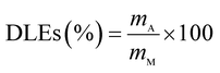
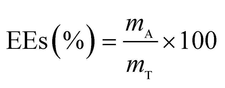
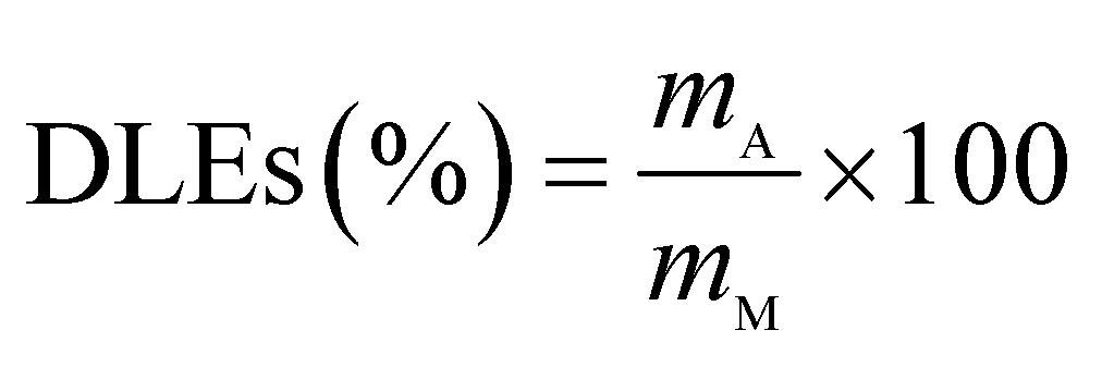
The drug release behavior of the microfibers was investigated in PBS at pH 7.4 ± 0.2. We selected 25 °C as the room temperature and 37 °C as the body temperature. To evaluate the maximum absorption wave of Enro, different Enro solutions were scanned from 200 nm to 400 nm using a UV-vis spectrophotometer (UV-2600, Japan), and the amount of Enro was calculated from the calibration curve. The encapsulation efficiencies (EEs) and drug loading efficiencies (DLEs) of the microfibers were determined using the following equations:34| |
 | (1) |
| |
 | (2) |
here, mA and mT are the actual and theoretical Enro contents of the microfiber, respectively, and mM is the weight of the dry microfibers.
The Enro-loaded microfibers (80 mg) were incubated in 80 mL PBS at 25 °C or 37 °C with constant shaking at 60 rpm. An 8.0 mL aliquot was periodically removed to quantify drug release with UV-vis; the same amount of fresh medium was added to maintain a volume of 80 mL. The results were presented in terms of cumulative release (CR, %). All release studies were performed in triplicate, and the results were reported as the average values ± S.D. CR was calculated according to the following equation:35
| |
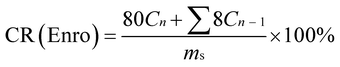 | (3) |
here,
Cn and
Cn−1 are the concentrations of Enro in the release media at
n and
n − 1 times, respectively,
n is the number of sample time points, and
ms denotes the initial amount of Enro-loaded.
2.6 Differential scanning calorimetry (DSC)
DSC was measured with a DSC200F3 instrument (Zetzsch, Germany) from 25 °C to 400 °C at a rate of 10 °C min−1 under nitrogen. The flow rate was 20 mL min−1.
2.7 Infrared imaging (IR imaging)
IR images were obtained using a Thermo Scientific Nicolet iN10 infrared microscope equipped with a liquid nitrogen-cooled MCT detector (Thermo Electron Corporation, USA). IR microscopy data were collected using reflection mode, and IR spectra were recorded from 4000 to 400 cm−1. Analysis of the IR microscopy data was performed using the OMNIC Picta software (Thermo Electron Corporation, USA).
2.8 Test of antibacterial activity
The antibacterial activities of PVDF/Enro and KGM/PVDF/Enro microfibers were tested with the inhibition-zone method.36 S. aureus and E. coli were cultivated in nutrient broth (3 g beef extract, 10 g peptone, and 5 g sodium chloride per 1000 mL water). S. aureus and E. coli (approximately 107 to 108 CFU mL−1) were then evenly spread over LB agar plates. The resulting samples (circular sheet, 10 mm diameter) were placed on the LB agar plates, and the plates were incubated at 37 °C for 24 h. The antibacterial effects of the samples were assessed by comparing the size of the inhibition zones, as measured with calipers.37
2.9 Wound dressing experiments
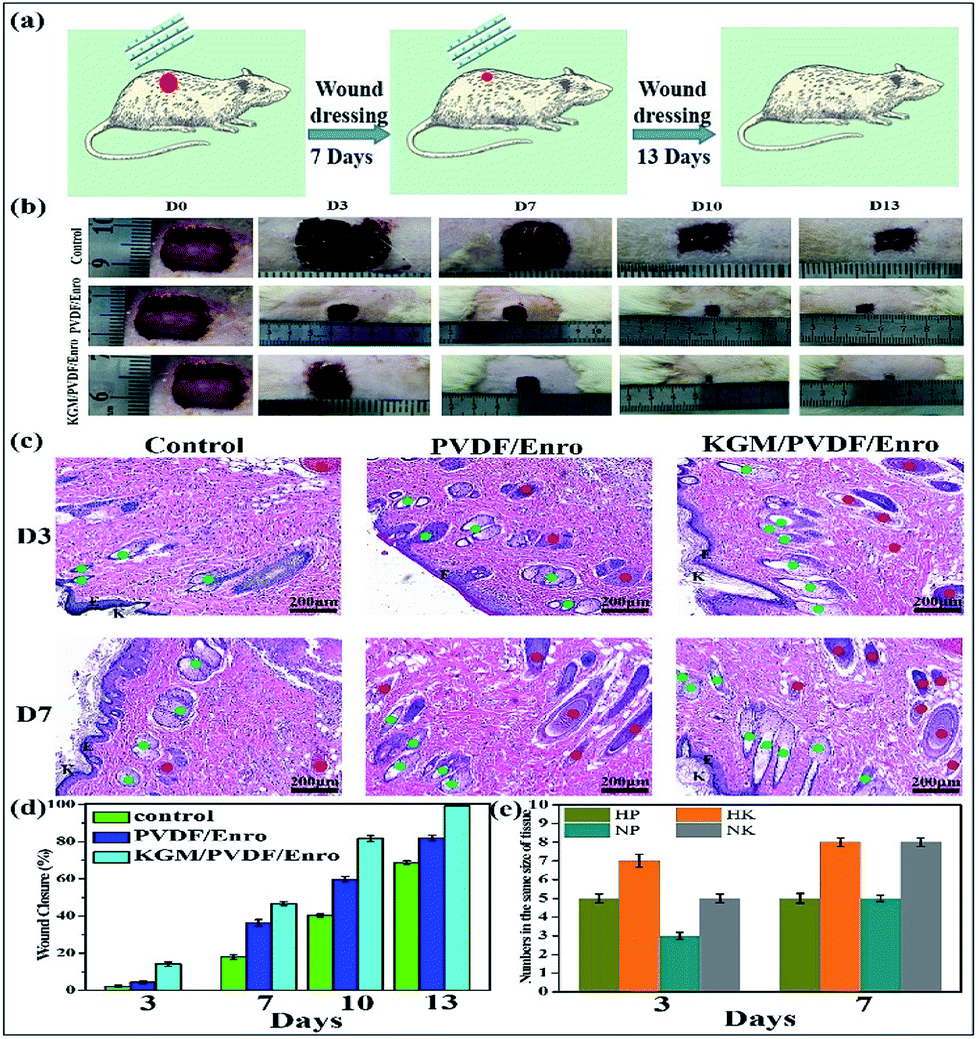
The wound healing experiments were performed at Fu Zhou General Hospital and approved by the Ethics Committee of Fu Zhou General Hospital (approval no. 2017-1220). International ethical guidelines and the National Institutes of Health Guide concerning the Care and Use of Laboratory Animals were strictly followed. Mice were obtained from the Fuzhou Institute of Experimental Animals (Fujian, China). Eight-week-old male Sprague Dawley rats (250 g; n = 18) were anesthetized and then, 1.2 cm × 1.2 cm wounds were created on the dorsum of the mice under sterile conditions.38 The mice were randomly divided into three groups: (i) control group (gauze covered), (ii) PVDF/Enro microfibers covered, and (iii) KGM/PVDF/Enro hybrid microfibers covered. The mice were recovered from anesthesia and housed in separate cages. A gross view of the wound was seen at 0, 3, 7, 10, and 13 days after operation. The wound closure rates were calculated based on comparisons with the original area of the wound. At 3 and 7 days, the mice were sacrificed, and the wounds were excised including a 5 mm surrounding area of the intact tissue. The tissues were immersed in paraformaldehyde (4%) for 24 h and then embedded in paraffin. After the paraffin was sectioned, hematoxylin–eosin (H&E) staining was performed for histological analysis.39
3. Results and discussion
3.1 In situ preparation of microfibers
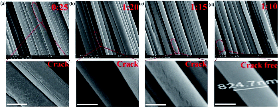
We started the successful construction of hybrid microfibers with the use of hydrophilic KGM and hydrophobic PVDF as spinning precursors. For the production of drug-loaded microfibers, we employed the drug Enro to load into the hybrid microfibers, allowing the microfibers to be used as wound dressings (Fig. 1). In a typical run, KGM/PVDF hybrid microfibers were prepared by changing the weight ratios of KGM and PVDF (0:25, 1:20, 1:15 and 1:10). Then, the ordered microfiber arrays were observed by SEM. As seen in Fig. 2a, the surface of pure PVDF microfibers was flat and rough, and it had several fissures. However, these fissures reduced with KGM enhancement (Fig. 2b and c). When the ratio of KGM:PVDF was 1:10 (w/w), the surfaces of the microfibers were smooth and crack-free (Fig. 2d). The diameter of the microfibers decreased with an increase in the flow rate. The microfiber with the smallest diameter was obtained with an average diameter of 824.7 ± 0.3 nm (Fig. 2d) under the conditions of 500 rad min−1 rotation and 80 Hz forward step. The core flow and sheath flow were fixed at 3 mL h−1 and 9 mL h−1, respectively.
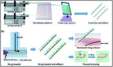 |
| | Fig. 1 (a) Schematic of the microfluidic preparation of KGM/PVDF crack-free hybrid microfibers. KGM/PVDF was chosen as the core flow, and the sheath flow was CH3OH for encapsulation in a T-shaped microfluidic platform. (b) Drug loading and release performance. Enrofloxacin (Enro) was loaded into the KGM/PVDF hybrid microfibers, and the Enro release performance was tested. The sample showed excellent sustained release performance and applications in wound dressing. | |
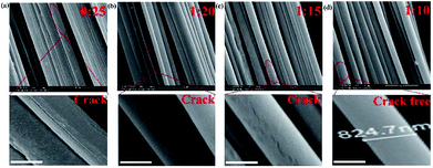 |
| | Fig. 2 (a) The SEM images of hybrid microfibers prepared with different weight ratios of KGM:PVDF: (a) 0:25, (b) 1:20, (c) 1:15, and (d) 1:10. Scale bars: 500 nm. | |
3.2 The characterization of hybrid microfibers
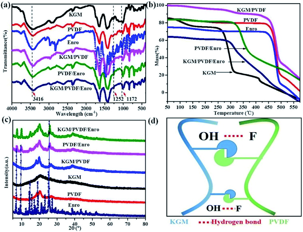
The IR spectra of the microfibers in the range from 4000 to 400 cm−1 are shown in Fig. 3a. KGM contains many hydroxyl groups, allowing it to be highly hydrophilic, and it can easily form hydrogen bonds.40 PVDF contains many C–F groups, allowing the segments to have hydrophobic properties.41 The absorption band near 3416 cm−1 represents the stretching vibration of O–H in KGM;40 the peak at 1252 cm−1 is due to the C–N stretching in Enro.42 The characteristic stretching vibrations noticed at 1172 cm−1 are due to C–F in PVDF.41 The KGM/PVDF or KGM/PVDF/Enro hybrid microfiber stretching frequencies shift to lower wavelengths at absorption band near 3416 cm−1, and the stretching vibrations become weaker at the absorption band at 1172 cm−1 versus KGM or PVDF (Fig. 3a), which indicates that many hydrogen bonds are formed between O–H and C–F (Fig. 3d). The strong hydrogen bonding strengthens the attraction between the molecules in the microfibers, and the cracks on the surface of the microfibers disappear. TGA details the thermal property of the microfibers (Fig. 3b). The weight of KGM remains unchanged until the temperature rises to 250 °C, at which the second stage begins. At this stage, the weight loss rate drops rapidly, and the sample loses 55% of its weight up to 325 °C. The weight of PVDF changes from 430 °C to 490 °C, and it loses 65% of its weight. However, in the case of KGM/PVDF, the situation is slightly different. The degradation in the second stage takes place at 460 °C, followed by a relatively gradual decline in weight until 500 °C. Unlike the results for KGM or PVDF, the temperature of KGM/PVDF at which decomposition begins in the second stage is higher. Furthermore, 45% of the total weight of KGM/PVDF is lost in this stage, whereas only about 55% or 65% of the weight of the counterpart is lost in the case of KGM or PVDF; this indicates that the hydrogen bond between KGM and PVDF provides powerful thermal stability. Similarly, there is a sharp decline in PVDF/Enro versus KGM/PVDF/Enro, which indicates that the KGM/PVDF/Enro hybrid microfibers are more thermally stable. The XRD patterns of microfibers are shown in Fig. 3c. It is shown that the strong peaks at 2θ that correspond to 20° and 25° are assigned to PVDF.43 No new visible signal is observed for the KGM/PVDF hybrid microfibers. For a hybrid containing KGM, no difference is found in the X-ray patterns.
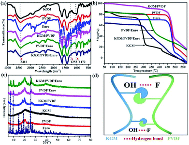 |
| | Fig. 3 (a) IR spectra of hybrid microfibers, (b) TGA patterns of hybrid microfibers, (c) XRD patterns of hybrid microfibers, and (d) hydrogen bond schematic between KGM and PVDF. | |
3.3 Drug release in vitro
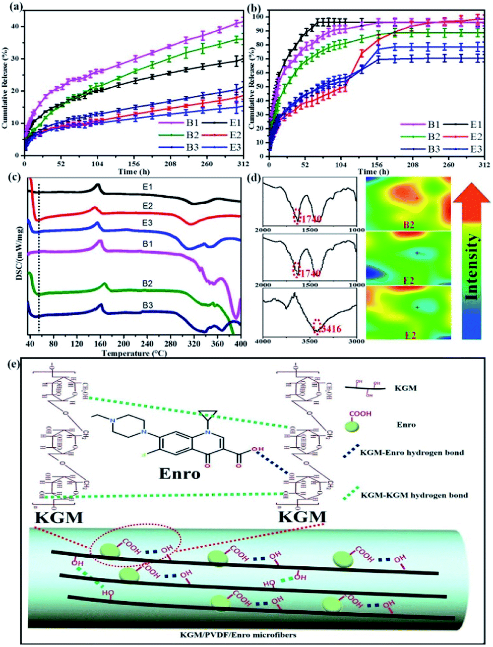
We investigated the drug release performance by IR imaging and Korsmeyer-Peppas model. The maximum absorption wave and calibration curve of Enro are shown in Fig. S1 and S2.† The hybrid microfibers exhibited a burst release of Enro during the first 15 h followed by a sustained released for 13 days (Fig. 4a and b). This phenomenon indicated that the hybrid microfibers are quite suitable for wound healing, which is a time-consuming process. Compared with others, E2 showed significantly higher (p < 0.05) EEs and DLEs (Table 1). Therefore, B2 and E2 as representatives were characterized by IR spectra and IR images to investigate the role of the functional groups (Fig. 4d). IR images show chemical changes from KGM addition and directly illustrate the distribution of carboxyl groups and hydroxyl groups through color variation (red represents high intensity and blue is low intensity). The uniform green color on the microfiber surface suggested that the carboxyl groups and hydroxyl groups were dispersed equally.44,45 B2 had a large number of dangling carboxyl groups (1740 cm−1) from Enro; the carboxyl groups became relatively uniform on E2. Similarly, hydroxyl groups from KGM became relatively uniform (3416 cm−1) on E2. These results suggested that hydrogen bondings between the hydroxyl groups on KGM or between hydroxyl groups and carboxyl groups (KGM–Enro) were formed.
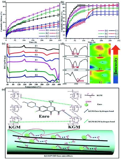 |
| | Fig. 4 (a) Cumulative release curves at 25 °C, (b) Cumulative release curves at 37 °C, and (c) DSC curves of the microfibers. (d) The IR spectra and IR images illustrate the distribution of the carboxyl groups and hydroxyl groups before and after KGM addition of microfibers. (e) Schematic representation of sustained drug release via hydrogen bonding. | |
Table 1 The encapsulation efficiencies (EEs) and drug loading efficiencies (DLEs) of hybrid microfibersa
| Sample |
E1 |
E2 |
E3 |
B1 |
B2 |
B3 |
| Data are expressed as the mean ± SD (n = 3), different superscript letters in the same column mean that values are significantly different (p < 0.05). |
| EEs (%) |
96.22 ± 2.48a |
98.5 ± 2.99a |
78.59 ± 3.45b |
96.1 ± 2.66a |
88.7 ± 2.99a |
70.46 ± 2.60a |
| DLEs (%) |
8.718 ± 0.03a |
13.4 ± 0.04a |
13.37 ± 0.06b |
9.5 ± 0.02a |
13.08 ± 0.04a |
13.29 ± 0.03a |
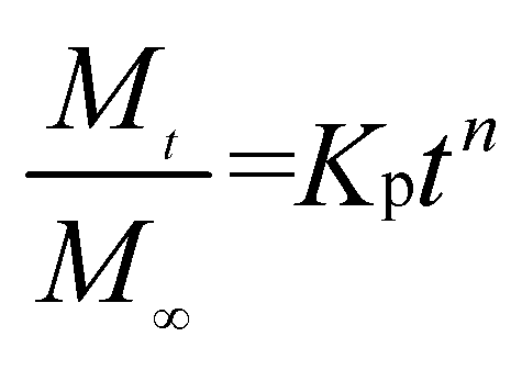
We further used the Korsmeyer-Peppas model46 to investigate the kinetics of Enro release:
| |
 | (4) |
here,

is the amount of drug release at time
t;
Kp is the Peppas release rate constant that is related to the properties of the release system, and
n is the release exponent, which illustrates the transport mechanism.
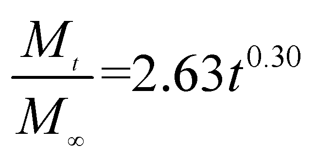
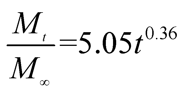
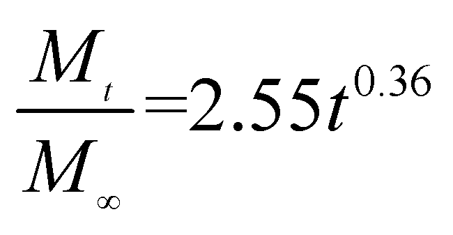
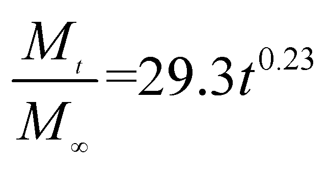
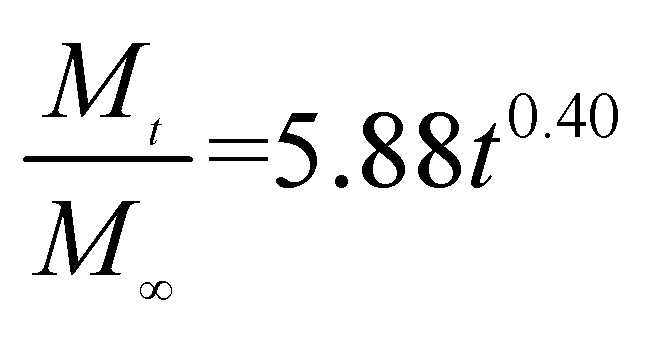
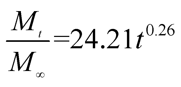
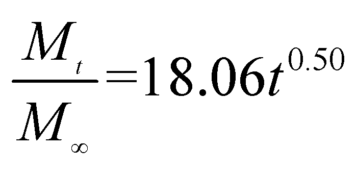
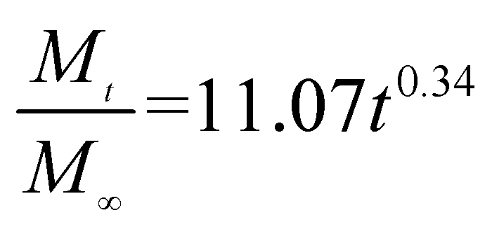
The release exponent (n) values for E1, E2, E3, B1, B2, and B3 at 25 °C were 0.33, 0.34, 0.30, 0.36, 0.47, and 0.36 (Table 2), respectively; at 37 °C, the values were 0.23, 0.40, 0.38, 0.26, 0.50, and 0.34 (Table 3), respectively, indicating that the main release mechanism is Fickian diffusion.47 The release exponent (n) of E2 was less than that of B2, indicating that KGM's attraction forces for Enro reduced the speed of Fickian diffusion. The Peppas release rate constant (Kp) of B2 was higher than that of E2, which could be due to PVDF's repulsive forces for drugs by C–F groups. Single KGM microfibers have been reported to have disadvantages of fast dissolution due to their high hydrophilicity.23,25 Single PVDF microfibers have low drug-loading capacity as a result of high hydrophobicity.43,48 In general, KGM enhanced the drug-loading capacity of the microfibers based on the strong hydrogen bonds formed between the hydroxyl groups on KGM or between hydroxyl groups and carboxyl groups (KGM–Enro); by using PVDF, we could solve the fast dissolution problem of KGM based on the hydrophobic C–F groups. The balance between hydrophilic KGM and hydrophobic PVDF enabled the microfibers to achieve sustained drug release for 13 days.
Table 2 Results of Enro release curves fitting into Korsmeyer-Peppas model at 25 °C
| Samples |
Equations |
R2 |
| E1 |
 |
0.9932 |
| E2 |
 |
0.9788 |
| E3 |
 |
0.9887 |
| B1 |
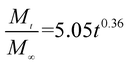 |
0.9923 |
| B2 |
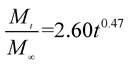 |
0.9970 |
| B3 |
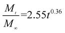 |
0.9898 |
Table 3 Results of Enro release curves fitting into Korsmeyer-Peppas model at 37 °C
| Samples |
Equations |
R2 |
| E1 |
 |
0.8904 |
| E2 |
 |
0.9651 |
| E3 |
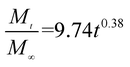 |
0.9855 |
| B1 |
 |
0.9299 |
| B2 |
 |
0.9472 |
| B3 |
 |
0.9839 |
Interestingly, more amounts of drug were released at 37 °C compared with that at 25 °C under the same conditions. By comparison, the CR values of E2 were 18.64 ± 1.14% at 25 °C and 98 ± 2.99% at 37 °C at 312 h (13 days). Similarly, the DSC curves exhibited fluctuation at low temperature (Fig. 4c), which suggested that the release performance of hybrid microfibers was temperature-sensitive. According to the literature, the amount of drug release increases with the increasing temperature,49 but such a large gap cannot be caused only by temperature. This was also due to the interactions between the hydrophilic KGM and hydrophobic PVDF, which can be beneficial for drug-loaded microfibers that will be stored for a long period of time.
3.4 Test of antibacterial activity
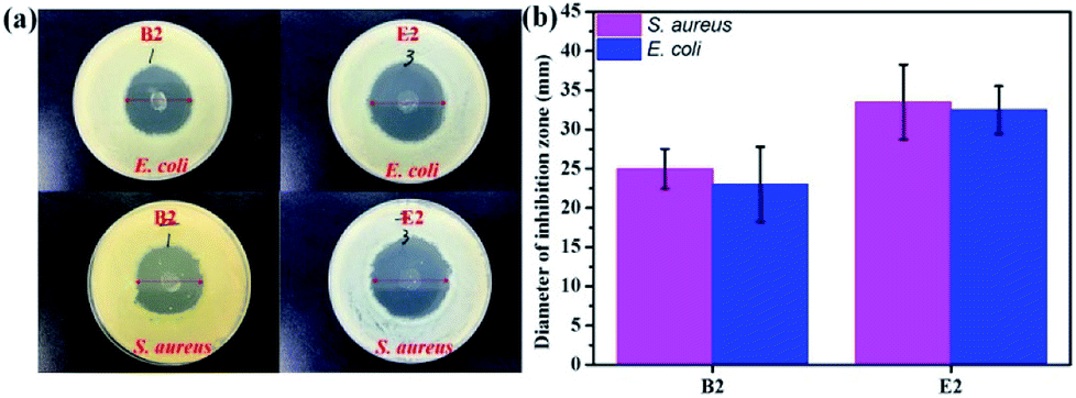
In vitro experiments were performed with E. coli and S. aureus to evaluate the antibacterial effects of the samples. The samples exhibited similar antibacterial effects against E. coli and S. aureus (Fig. 5). Clear zones surrounding B2 and E2 are shown in Fig. 5a. However, the antibacterial performance of B2 was slightly inferior to that of E2 due to its initial burst release, which indicated that E2 had better sustained drug release performance. It is well-known that a drug can cause waste and produce toxic side effects upon fast release. An extreme slow release results in low efficiency germicidal activity.51 Antibacterial experiments showed that the KGM/PVDF/Enro hybrid microfibers had a continuous bactericidal effect. Meanwhile, KGM played a supporting role in the sterilization of drugs. The high antibacterial activity of E2 suggested better wound-healing capability.50
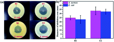 |
| | Fig. 5 Antibacterial activities evaluated by the zone of inhibition assay against E. coli and S. aureus; (a) photos of inhibition zone, (b) diameter of inhibition zone. | |
3.5 Applications in mice wound healing
Finally, we used these microfibers as wound dressings for in vivo wound healing experiments. The drug release and antibacterial activity experiments described above showed that the hybrid microfibers possessed excellent sustained drug release performance and antibacterial properties. We assessed the degree of healing in terms of wound size. Fig. 6b and d show the wound closure macroscopic images and quantification analysis of the healing process of different test groups on the closure rate. It is clear that the hair follicles and neovascularization were observed, and the wound area gradually reduced. In contrast to the ones that were gauze-covered, fewer hair follicles and neovascularization were observed for the wounds covered with the PVDF/Enro microfibers. Significantly, for the wounds treated with the KGM/PVDF/Enro hybrid microfibers, more neovascularization and mature hair follicles were observed in the regenerated epidermis at the same size of the tissue (Fig. 6c and e). The wounds covered with the KGM/PVDF/Enro hybrid microfibers also showed a faster healing process than the observations for the other two groups. Particularly, by day 13, 99.3 ± 0.1% of the injured area had reepithelialized after treatment with KGM/PVDF/Enro hybrid microfibers. In contrast, only 82 ± 1.48% and 68.7 ± 0.96% of the wound areas had healed when PVDF/Enro microfibers and gauze, respectively, were used (Fig. 6d). This can be ascribed to the hybrid microfibers' sustained drug release for 13 days based on the balance between hydrophilic KGM and hydrophobic PVDF, which reduced the repeated pain caused during the replacement of wound dressings.52–54 The results further demonstrated that the KGM/PVDF hybrid microfibers have excellent sustained drug release performance. Particularly, these hybrid microfibers having hydrophilic and hydrophobic segments produced via the microfluidic spinning concept can promote wound healing and tissue regeneration.
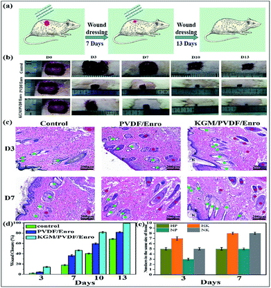 |
| | Fig. 6 Effects of PVDF/Enro, KGM/PVDF/Enro microfibers on wound healing, control group (gauze covered) used for comparison. (a) Schematic representation of the healing wound, (b) photographic evaluations of the healing process, (c) histology of wounds at 3 days and 7 days. K: keratin layer, Epi: epidermis, N: neovascularization ( ), F: hair follicles ( ), F: hair follicles ( ), (d) ratio of wound closure during wound healing, (e) numbers in the same size of tissue. HP: keratin layer of PVDF/Enro microfibers, HK: keratin layer of KGM/PVDF/Enro hybrid microfibers, NP: neovascularization of PVDF/Enro microfibers, NK: neovascularization of KGM/PVDF/Enro hybrid microfibers. ), (d) ratio of wound closure during wound healing, (e) numbers in the same size of tissue. HP: keratin layer of PVDF/Enro microfibers, HK: keratin layer of KGM/PVDF/Enro hybrid microfibers, NP: neovascularization of PVDF/Enro microfibers, NK: neovascularization of KGM/PVDF/Enro hybrid microfibers. | |
4. Conclusions
In summary, we report a simple and rapid strategy for the in situ preparation of KGM/PVDF hybrid microfibers as a novel wound dressing via microfluidic spinning. The interaction between hydrophilic KGM and hydrophobic PVDF resulted in hybrid microfibers that exhibited crack-free surface, excellent heat resistance and sustained drug release performance. More specifically, the hydrogen bonds formed between O–H of the hydrophilic KGM and C–F of the hydrophobic PVDF resulted in hybrid microfibers having crack-free surfaces and excellent heat resistance; the balance between KGM's attraction forces, which are produced by the hydrogen bonds (KGM–KGM or KGM–Enro), and PVDF's repulsive forces, which are formed due to the existence of C–F groups, promoted sustained drug release for 13 days. This wound dressing has excellent antibacterial activity against E. coli and S. aureus and can reduce repeated pain caused by the replacement of a wound dressing. A new hydrophilic/hydrophobic drug carrier structure has been designed, which has solved the fast dissolution problem of KGM and the low drug-loading capacity demerit of PVDF; it can also reduce the possibility of generating cracks in the field of micromanipulation. This tool is potentially useful for various applications in biomaterials.
Conflicts of interest
There are no conflicts to declare.
Acknowledgements
This work was supported by the National Natural Science Foundation of China (31772045, 31471704). The authors thank Janus New-Materials Co., Ltd. for assistance with microfluidic spinning technique. The authors thank Qing Li for valuable discussion on preparation of the experiment.
Notes and references
- N. C. Tansil, L. D. Koh and M. Y. Han, Adv. Mater., 2012, 24, 1388–1397 CrossRef PubMed.
- S. Zhao, L. Li, H. Wang, Y. Zhang, X. Cheng, N. Zhou, M. N. Rahaman, Z. Liu, W. Huang and C. Zhang, Biomaterials, 2015, 53, 379–391 CrossRef PubMed.
- P. Martin, Science, 1997, 276, 75–81 CrossRef PubMed.
- A. H. Najafabadi, A. Tamayol, N. Annabi, M. Ochoa, P. Mostafalu, M. Akbari, M. Nikkhah, R. Rahimi, M. R. Dokmeci, S. Sonkusale, B. Ziaie and A. Khademhosseini, Adv. Mater., 2014, 26, 5823–5830 CrossRef PubMed.
- I. Liakos, L. Rizzello, H. Hajiali, V. Brunetti, R. Carzino, P. P. Pompa, A. Athanassiou and E. Mele, J. Mater. Chem. B, 2015, 3, 1583–1589 RSC.
- N. Elkhatib, E. Bresteau, F. Baschieri, A. L. Rioja, G. V. Niel, S. Vassilopoulos and G. Montagnac, Science, 2017, 356, 1–8 CrossRef PubMed.
- X. Zhao, H. Wu, B. Guo, R. Dong, Y. Qiu and P. X. Ma, Biomaterials, 2017, 122, 34–47 CrossRef PubMed.
- C. Zhong, T. Gurry, A. A. Cheng, J. Downey, Z. Deng, C. M. Stultz and T. K. Lu, Nat. Nanotechnol., 2014, 9, 858–866 CrossRef PubMed.
- A. Q. Chen, H. C. He, G. L. Ma, Y. Li, S. S. Jiang, X. Xuan, Y. Song, C. Y. Zhang, J. Xiao, Y. S. Xu, J. Wu and S. F. Chen, RSC Adv., 2018, 8, 10620–10626 RSC.
- A. Khalid, H. Ullah, M. Ul-Islam, R. Khan, S. Khan, F. Ahmad, T. Khan and F. Wahid, RSC Adv., 2017, 7, 47662–47668 RSC.
- S. Shabahang, G. Tao, J. J. Kaufman, Y. Qiao, L. Wei, T. Bouchenot, A. P. Gordon, Y. Fink, Y. Bai, R. S. Hoy and A. F. Abouraddy, Nature, 2016, 534, 529–533 CrossRef PubMed.
- A. T. Haedler, K. Kreger, A. Issac, B. Wittmann, M. Kivala, N. Hammer, J. Kohler, H. W. Schmidt and R. Hildner, Nature, 2015, 523, 196–199 CrossRef PubMed.
- A. Bloessera, P. Voepela, M. O. Loeha, A. Beyerb, K. Volzb and R. Marschalla, J. Mater. Chem. A, 2018, 6, 1971–1978 RSC.
- D. Psaltis, S. R. Quake and C. Yang, Nature, 2006, 442, 381–386 CrossRef PubMed.
- D. Li, A. Babel, S. A. Jenekhe and Y. Xia, Adv. Mater., 2004, 16, 2062–2066 CrossRef.
- G. F. J. Müller, M. Stürzel and R. Mülhaupt, Adv. Funct. Mater., 2014, 24, 2860–2864 CrossRef.
- R. J. DeVolder, H. Bae, J. Lee and H. Kong, Adv. Mater., 2011, 23, 3139–3143 CrossRef PubMed.
- G. M. Whitesides, Nature, 2006, 442, 368–373 CrossRef PubMed.
- R. V. Bell, C. C. Parkins, R. A. Young, C. M. Preuss, M. M. Stevens and S. A. F. Bon, J. Mater. Chem. A, 2016, 4, 813–818 RSC.
- M. Y. Jiang, X. J. Ju, K. Deng, X. X. Fan, X. H. He, F. Wu, F. He, Z. Liu, W. Wang, R. Xiea and L. Y. Chu, J. Mater. Chem. B, 2016, 4, 3925–3935 RSC.
- E. K. Sackmann, A. L. Fulton and D. J. Beebe, Nature, 2014, 507, 181–189 CrossRef PubMed.
- Y. Zhang, Y. Tian, L. L. Xu, C. F. Wang and S. Chen, Chem. Commun., 2015, 51, 17525–17528 RSC.
- R. J. Mu, Y. Ni, L. Wang, Y. Yuan, Z. Yan, J. Pang and S. Chen, Mater. Lett., 2017, 196, 410–413 CrossRef.
- Y. S. Zhang and A. Khademhosseini, Science, 2017, 356(6337), eaaf3627 CrossRef PubMed.
- Y. Ni, R. J. Mu, X. D. Tan, R. X. Huang, Y. Yuan, H. B. Chen and J. Pang, Struct. Chem., 2017, 36, 1043–1048 Search PubMed.
- R. J. Mu, Y. Yuan, L. Wang, Y. Ni, M. Li, H. Chen and J. Pang, Food Hydrocolloids, 2018, 76, 42–48 CrossRef.
- L. Wu, X. Lin, J. Wu, X. Zhou and X. Luo, RSC Adv., 2016, 6, 89417–89429 RSC.
- L. Persano, C. Dagdeviren, Y. Su, Y. Zhang, S. Girardo, D. Pisignano, Y. Huang and J. A. Rogers, Nat. Commun., 2013, 4, 1633–1643 CrossRef PubMed.
- Z. L. Luo, Y. Li, C. Duan and B. B. Wang, RSC Adv., 2018, 8, 16251–16259 RSC.
- C. Wan and C. R. Bowen, J. Mater. Chem. A, 2017, 5, 3091–3128 RSC.
- C. D. Ma, C. Wang, C. Acevedo-Velez, S. H. Gellman and N. L. Abbott, Nature, 2015, 517, 347–363 CrossRef PubMed.
- T. He, J. Wang, P. Huang, B. Zeng, H. Li, Q. Cao, S. Zhang, Z. Luo, D. Y. Deng, H. Zhang and W. Zhou, Colloids Surf., B, 2015, 130, 278–286 CrossRef PubMed.
- S. S. Behera and R. C. Ray, Int. J. Biol. Macromol., 2016, 92, 942–956 CrossRef PubMed.
- Y. Yuan, L. Wang, R. J. Mu, J. N. Gong, Y. Wang, Y. Li, J. Ma, J. Pang and C. Wu, Carbohydr. Polym., 2018, 190, 196–203 CrossRef PubMed.
- J. Tang, J. Mi, W. Huang, H. Zhong, Y. Li, J. Zhou and A. M. Johri, J. Mater. Chem. B, 2018, 6, 1920–1929 RSC.
- Y. Lyu, H. Ren, M. Yu, X. Li, D. Li and C. Mu, Carbohydr. Polym., 2017, 174, 1095–1105 CrossRef PubMed.
- D. Q. Wu, H. C. Cui, J. Zhu, X. H. Qin and T. Xie, J. Mater. Chem. B, 2016, 4, 2606–2613 RSC.
- W. C. Lin, C. C. Lien, H. J. Yeh, C. M. Yu and S. H. Hsu, Carbohydr. Polym., 2013, 94, 603–611 CrossRef PubMed.
- Q. Li, Y. Niu, H. Diao, L. Wang, X. Chen, Y. Wang, L. Dong and C. Wang, Biomaterials, 2017, 148, 54–68 CrossRef PubMed.
- Z. Li, Y. Su, B. Xie, X. Liu, X. Gao and D. Wang, J. Mater. Chem. B, 2015, 3, 1769–1778 RSC.
- J. Lv, G. Zhang, H. Zhang, C. Zhao and F. Yang, Appl. Surf. Sci., 2018, 440, 1091–1100 CrossRef.
- L. Zhang, D. Dong, X. Hua and Z. Guo, Sci. Total Environ., 2018, 625, 178–184 CrossRef PubMed.
- B. Luo, X. Wang, Y. Wang and L. Li, J. Mater. Chem. A, 2014, 2, 510–519 RSC.
- C. Xu, Q. Li, X. T. Hu, C. F. Wang and S. Chen, J. Mater. Chem. B, 2017, 5, 3816–3822 RSC.
- C. Yu, C. F. Wang and S. Chen, J. Mater. Chem. A, 2015, 3, 17351–17358 RSC.
- A. Tamayo, M. A. Mazo, M. D. Veiga, R. Ruiz-Caro, F. Notario-Perez and J. Rubio, Mater. Sci. Eng., C, 2017, 75, 1097–1105 CrossRef PubMed.
- J. D. Obayemi, Y. Danyuo, S. Dozie-Nwachukwu, O. S. Odusanya, N. Anuku, K. Malatesta, W. Yu, K. E. Uhrich and W. O. Soboyejo, Mater. Sci. Eng., C, 2016, 66, 51–65 CrossRef PubMed.
- D. Li, Y. Wang, J. Hu, B. Lu, D. Dang, J. Zhang and Y. T. Cheng, J. Power Sources, 2018, 387, 9–15 CrossRef.
- Y. Xu, J. J. Li, D. J. Yu, G. R. Williams, J. H. Yang and X. Wang, Eur. J. Pharm. Sci., 2017, 106, 422–430 CrossRef PubMed.
- D. Simoes, S. P. Miguel, M. P. Ribeiro, P. Coutinho, A. G. Mendonca and I. J. Correia, Eur. J. Pharm. Biopharm., 2018, 127, 130–141 CrossRef PubMed.
- D. Mishraa, P. Kharea, D. K. Singhb, S. Luqmanb, P. V. A. Kumarc, A. Yadavc, T. Dasd and B. K. Saikiad, Ind. Crops Prod., 2018, 114, 68–80 CrossRef.
- M. Naseri-Nosar and Z. M. Ziora, Carbohydr. Polym., 2018, 189, 379–398 CrossRef PubMed.
- S. F. Chou, D. Carson and K. A. Woodrow, J. Controlled Release, 2015, 220, 584–591 CrossRef PubMed.
- E. Pinho and G. Soares, J. Mater. Chem. B, 2018, 6, 1887–1898 RSC.
Footnote |
| † Electronic supplementary information (ESI) available. See DOI: 10.1039/c8ra05600e |
|
| This journal is © The Royal Society of Chemistry 2018 |
Click here to see how this site uses Cookies. View our privacy policy here. 
 Open Access Article
 This Open Access Article is licensed under a Creative Commons Attribution-Non Commercial 3.0 Unported Licence
 *b and
Jie Pang*a
*b and
Jie Pang*a


 is the amount of drug release at time t; Kp is the Peppas release rate constant that is related to the properties of the release system, and n is the release exponent, which illustrates the transport mechanism.


 ), F: hair follicles (
 ), (d) ratio of wound closure during wound healing, (e) numbers in the same size of tissue. HP: keratin layer of PVDF/Enro microfibers, HK: keratin layer of KGM/PVDF/Enro hybrid microfibers, NP: neovascularization of PVDF/Enro microfibers, NK: neovascularization of KGM/PVDF/Enro hybrid microfibers.