
 Open Access Article
 This Open Access Article is licensed under a Creative Commons Attribution-Non Commercial 3.0 Unported Licence
Immobilization of g-C3N4 nanosheets on diatomite via electrostatic adsorption and their photocatalytic activity
Xiaofeng Hu ab,
Lixun Dengab,
Hua Ouyangab and
Huihu Wang*ab
ab,
Lixun Dengab,
Hua Ouyangab and
Huihu Wang*ab
aHubei Provincial Key Laboratory of Green Materials for Light Industry, Hubei University of Technology, Wuhan, P. R. China. E-mail: wanghuihu@hbut.edu.cn; Fax: +86-027-59750460; Tel: +86-027-59750460
bSchool of Materials and Chemical Engineering, Hubei University of Technology, Wuhan, P. R. China
First published on 6th August 2018
Abstract
Graphitic carbon nitride (g-C3N4) nanosheets have been successfully immobilized on diatomite to form a g-C3N4/diatomite hybrid through a facile electrostatic adsorption method and subsequent calcination process. Electron microscopy studies confirm that the surface of the diatomite is tightly covered with g-C3N4 nanosheets. In addition, the characterization results of Fourier transform infrared spectra (FTIR) and X-ray photoelectron spectra (XPS) verify that there is a strong interaction between the g-C3N4 and diatomite components inside the hybrids. The visible light absorption edge of the hybrids exhibits a significant redshift compared with the bare g-C3N4 nanosheets and diatomite, which leads to the improvement of visible light absorption and utilization. The photocatalytic results demonstrated that the photocatalytic performance for methyl orange and phenol degradation using the hybrids as photocatalysts has been obviously improved compared to that of g-C3N4 nanosheets, which may be ascribed to its adsorption/photocatalysis synergistic effect.
Introduction
New methods for pollution prevention and treatment have attracted more and more attention in the past decades.1 Compared with the conventional methods, photocatalysis is regarded as one of the most effective and safest approaches at lower cost and with less energy consumption,2 thus receiving extensive attention from governments and people. In 2009, g-C3N4 was first reported as a metal-free photocatalyst that has an adjustable electronic structure, and stable physical and chemical properties.3 Furthermore, the band gap of g-C3N4 is around 2.7 eV; thus it can be excited by visible light in the solar spectrum. More importantly, g-C3N4 can be easily synthesized by calcination using various precursors such as urea, dicyanodiamine, melamine or their mixtures.4 Due to these characteristics, g-C3N4 has been widely used to degrade water contaminants, such as rhodamine B (RhB),5 methylene blue (MB),6 methyl orange (MO)7 and phenol.8 The fabrication and application of g-C3N4 for environmental treatments has become a hot issue in recent years.Nevertheless, g-C3N4 bulks still exist many non-negligible shortcomings, such as low visible light availabilities, fast recombination rate of photoelectrons and holes, tiny surface area and difficult recycling and reusing.9 To address these problems, g-C3N4 nanostructures, such as exfoliated g-C3N4 nanosheets,10 macroscopic foam-like holey ultrathin g-C3N4 nanosheets,11 g-C3N4 nanorods,12 g-C3N4 quantum dots13 and other special structures14 were designed. Many binary and ternary composites based on g-C3N4 have been developed, including TiO2/g-C3N4,15 MoO3/g-C3N4,16 MoS2/g-C3N4,17 BiOI/g-C3N4,18 rGO/g-C3N4,19 CdS/g-C3N4,20 Ag3VO4/g-C3N4,21 Ag2WO4/g-C3N4,22 AgIO3/g-C3N4,23 Ag/AgBr/g-C3N4,24 and CdS/Au/g-C3N4.25 Doping26 and metal deposition27 were also used to modify g-C3N4 surface. However, most of the previous works were focused on improving their photocatalytic activities. The immobilization of g-C3N4 on solid support has not yet received much attention. It is known that poor recycling of photocatalyst powder is one of the shortcomings for its practical applications. Without a suitable solid support, g-C3N4 would not be used adequately.9 Till now, several studies have reported the immobilization of g-C3N4 on the agar,9 polyaniline,28 graphene,29 ceramic foam,30 and ITO glass.31 Despite that, immobilizing g-C3N4 on solid support remains a challenge work because of its enormous size and tiny surface area.
On the other hand, adsorption is also an effective way to dispose the liquid contaminants because of its cheap price.32 In the conventional pollution treatment methods, diatomite is often used as adsorbent because of its large specific surface area and plentiful surface silicon hydroxyl groups.33 Moreover, due to its high porosities, good physical properties and favorable chemical inertness, diatomite is also used as solid support for catalysts immobilization.34 As adsorption is also one of the key steps in photocatalysis, the synergistic effect of adsorption and photocatalysis may be obtained by combining photocatalysts and diatomite to fabricate hybrids.35,36 Due to the small size of nanoparticles, ZnO and TiO2 have been successfully supported on diatomite to form ZnO/diatomite37 and TiO2/diatomite hybrids.38 Limited by the wide band gap of TiO2 and ZnO, the hybrids exhibited the poor visible light activity. To enhance the visible light performance of TiO2/diatomite hybrids, a little amount of g-C3N4 components were introduced in the TiO2/diatomite hybrids to fabricate ternary g-C3N4/TiO2@diatomite hybrids. However, the total introduced g-C3N4 amount in the ternary hybrids was seriously restricted because of its large size and tiny surface area. Thus, it is highly desired to develop visible light active g-C3N4/diatomite hybrids with enhanced adsorption/photocatalysis performance.
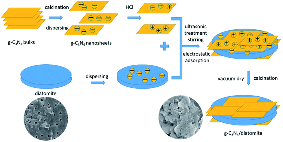
In this work, the thermal exfoliated g-C3N4 nanosheets (SCN) were selected as precursors to combine with diatomite. Through the pre-treatment of SCN and diatomite, the two components were self-assembled by electrostatic adsorption at first. Then a simple calcination process was carried out to realize the immobilization of g-C3N4 on the surface of diatomite. The enhanced adsorption/photocatalysis performance of this hybrid has been investigated using MO and phenol as pollutant models. The photocatalytic mechanism over the hybrids was also studied.
Experimental
Materials
Diatomite (purity > 85%), phenol (C6H6O), urea (H2NCONH2), dicyanodiamine (C2H4N4) and other chemical reagents were purchased from Sinopharm Chemical Reagent Beijing Co., Ltd. Methyl orange (C14H14N3NaO3S, MO) was obtained from Aladdin Biochemical Technology Shanghai Co., Ltd. All reagents used in the experiments were of analytical grade. Ultrapure water was used throughout all the experiments.Synthesis of g-C3N4 nanosheets
g-C3N4 nanosheets can be obtained by the delamination of bulk g-C3N4 through thermal oxidation etching process.39 Typically, urea and dicyandiamide were weighed and placed in a jar mill at a mass ratio of 7![[thin space (1/6-em)]](https://www.rsc.org/images/entities/char_2009.gif) :3. After milling at 360 rpm for 60 min, 5 g of milled powder was put into a ceramic crucible with lid and heated at 550 °C for 4 h with the ramping rate of 2 °C min−1. The as-obtained light-yellow product was milled into powder and put in another uncovered ceramic crucible which was heated to 520 °C for 2 h with the ramping rate of 5 °C min−1 in the muffle furnace. The as-prepared white products were collected for further use and denoted as SCN.
:3. After milling at 360 rpm for 60 min, 5 g of milled powder was put into a ceramic crucible with lid and heated at 550 °C for 4 h with the ramping rate of 2 °C min−1. The as-obtained light-yellow product was milled into powder and put in another uncovered ceramic crucible which was heated to 520 °C for 2 h with the ramping rate of 5 °C min−1 in the muffle furnace. The as-prepared white products were collected for further use and denoted as SCN.
Pre-treatment of diatomite and g-C3N4 nanosheets
Diatomite should be purified to remove the impurities.40 After calcination at 500 °C for 5 h with the ramping rate of 5 °C min−1, diatomite was put into NaOH solution (5 wt%), sonicated for 10 min and stirred constantly for 1 h at 45 °C. Then, the resulting suspensions were filtered and freeze-dried in a vacuum for 6 h. After that, the powders were put into H2SO4 (40 wt%) solution, sonicated for 10 min and stirred continuously for 75 min at 50 °C. Finally, the mixtures were filtered and freeze-dried under vacuum for 6 h. The products were collected for further use. For the pre-treatment of g-C3N4 nanosheets, 1 g of SCN was dispersed in 100 mL of HCl solution (1 mol L−1). The suspensions were sonicated for 1 h and vigorously stirred for another 8 h. Finally, the suspensions were filtered and freeze-dried in a vacuum for 6 h.Synthesis of g-C3N4/diatomite hybrids
The pre-treated g-C3N4 nanosheets and diatomite were weighed and mixed in 100 mL of solution at first. Then the mixtures were sonicated for 30 min and stirred for 60 min in order to keep the two components closely attract together through the electrostatic adsorption. After filtration and overnight of drying in the oven at 100 °C, the powders were heated at 500 °C for 2 h with the ramping rate of 2.5 °C min−1, and then the final g-C3N4/diatomite hybrids were obtained. According to the theoretical mass ratio of g-C3N4 to diatomite (5:1, 10:1, 15:1 and 20:1), the final obtained products were labelled as S5, S10, S15 and S20, respectively. A mechanical mixture of SCN and diatomite with a mass ratio of 15:1 was also prepared for comparison, labeled as M15.
Characterization
Powder X-ray diffraction (XRD) patterns of samples were collected using a D8 Advance X-ray diffractometer (Bruker) with Cu-Kα radiation at 40 kV and 40 mA. The scan rate was set as 2° min−1 and the scanning range of 2θ was from 10° to 90°. Scanning electron microscopy (SEM) images were taken on a SU-8000 scanning electron microscope (Hitachi) equipped with energy dispersive spectrum (EDS). The structures of samples were recorded by transmission electron microscopy (TEM) performed on a Tecnai G20 transmission electron microscope (FEI). Thermal gravimetric (TG) and differential scanning calorimetry (DSC) were determined by a STA 449F5 simultaneous thermal analyser (Netzsch) to analyse the thermal physical and chemical properties of as-prepared samples. The test temperature ranged from 30 °C to 800 °C in the air. Specific surface areas were measured by Autosorb iQ Station (Quantachrome) with N2 as the analysis gas. Prior to the measurement, the samples were under aspiration at 100 °C for 3 h. The zeta potential was analyzed by a JS94H microscopic electrophoresis apparatus (Powereach) under neutral conditions. To study the optical properties of samples, Fourier transform infrared spectra (FTIR) and diffuse-reflection spectra (DRS) were carried out and performed on NEXUS-6700 FTIR spectrometer (Nicolet) and U-3900 UV-vis spectrophotometer (Hitachi), respectively. The references were KBr and BaSO4. A VG multilab 2000X X-ray photoelectron spectrometer (XPS) with Al-Kα radiation was applied to analyses the surface element compositions and chemical bond states of the photocatalysts.Evaluation of photocatalytic activity
The photocatalytic activity of hybrids was evaluated by the degradation of MO and phenol solution under visible light irradiation. A 300 W xenon lamp (CEL-HXF300, AuLight Co. Ltd.) with a 400 nm visible light filter was used as light source. For MO photodegradation experiments, 0.1 g of as-prepared hybrids was dispersed into 100 mL of MO aqueous solution with concentration 10 mg L−1 at first. Prior to irradiation, the mixed suspensions were sonicated for 15 min and then stirred in the dark for 30 min to reach an adsorption–desorption equilibrium. In the process of irradiation, continuous stirring and pumping air was applied to keep the photocatalytic reaction homogeneously in the suspensions. 2 mL of suspensions was intermittently sampled. The concentration of MO was determined with a UV-2102PC UV-vis spectrophotometer (Unico) at 464 nm. For the photodegradation of phenol solution, the detailed process was similar as MO degradation experiment. The original concentration of phenol solution was set as 8 mg L−1. The concentration of sampled phenol solution was analysed using a Dinoex UltiMate 3000 high performance liquid chromatography (HPLC, ThermoFisher). The recycling tests for MO degradation over the hybrid S15 were conducted to investigate the stability of photocatalysts. After each degradation experiment, the hybrid was collected and washed three times with absolute ethanol and ultrapure water, and then dried at 60 °C before next use.Result and discussion
Fig. 1 shows the XRD patterns of diatomite, SCN, and as-prepared hybrids with different mass ratio of SCN to diatomite. For diatomite, three strong diffraction peaks at around 21.8°, 31.1° and 35.9° are observed in Fig. 1a, corresponding to the (101), (102) and (200) planes of cristobalite phase. From Fig. 1a and b, the XRD data of SCN shows two diffraction peaks at 12.9° and 27.7° which can be assigned to the (100) plane and (002) plane of graphitic phase.41 It is worth nothing that the peak of SCN at 12.9° is inconspicuous, indicating the effective exfoliation were achieved through thermal oxidation etching process.42 For hybrids, both diffraction peaks of two components are found in the patterns. Especially, the two peaks at 21.8° and 27.7° attributed to graphitic phase and cristobalite phase are distinct. No new diffraction peaks are formed in the XRD patterns of hybrids. Furthermore, the peak intensity corresponding to SCN is enhanced with the increase of SCN contents in the hybrids, while the peak intensity assigned to diatomite decreases obviously.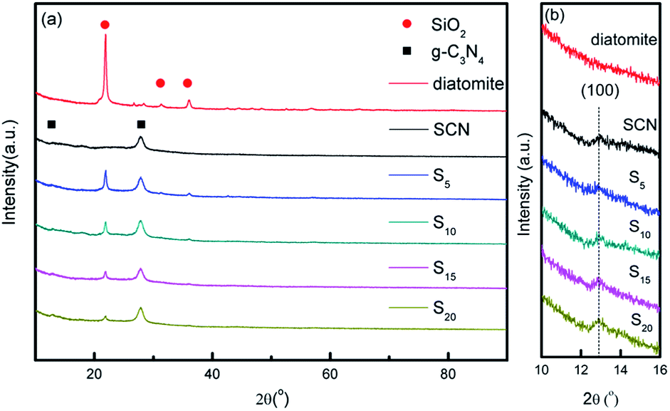 | ||
| Fig. 1 XRD patterns of diatomite, SCN, and as-prepared hybrids (a) and partial enlarged patterns from 10–16° (b). | ||
The detailed morphological characterization and chemical composition of diatomite and as-prepared hybrids are based on SEM, EDS and TEM analysis. Fig. 2a and b present the two typical shapes of diatomite: disc shape and cylindrical shape with porous structure. The surface of diatomite is relatively smooth and clean. After the SCN components are immobilized on the surface of diatomite, it can be observed that the surface of hybrid becomes rougher compared with that of pure diatomite, shown in Fig. 2c and d.
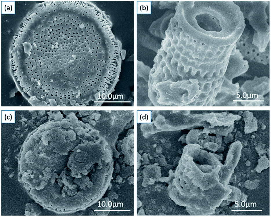 | ||
| Fig. 2 SEM images of diatomite (a and b) and as-prepared hybrid S15 (c and d). | ||
Fig. 3 shows the SEM images and EDS spectra of diatomite, hybrid S5 and S15. In Fig. 3c, it can be seen the diatomite is partially covered with SCN and a few of pores in diatomite can be observed. However, no pores are found on the surface of hybrid S15, indicating the surface of diatomite is completely covered with SCN, as shown in Fig. 3e. For pure diatomite, the main chemical compositions are C, Si and O elements, as shown in Fig. 3b. The analysis point is labelled with red cross in Fig. 3a. For hybrids, C, Si, O, and N elements are observed in Fig. 3d and f. The corresponding analysis points are labelled in Fig. 3c and e, respectively. As the N element is originated from SCN and Si comes from diatomite, the atomic ratio of Si to N element in the different samples is calculated. For pure diatomite, hybrid S5 and S15, the atomic ratio of Si to N is 28.55, 0.501, and 0.006, respectively. With the increase of SCN contents in the hybrids, the atomic ratio of Si to N sharply decreases. Thus, the atomic ratio of Si to N element can be used to estimate the surface coverage of hybrids. This result is also consistent with the SEM images in Fig. 3a, c and e. Au element is also detected in the EDS spectra because the Au coating is sprayed on the surface of samples to enhance its conductivity before SEM operation. Notably, the morphology of hybrids is slightly different from that in Fig. 2. It is a part of a diatomite disc rather than an entire one. Due to the high temperature and vigorous stirring, diatomite would be broken into small pieces in the experiment, rarely showing a complete disc or cylindrical shape.
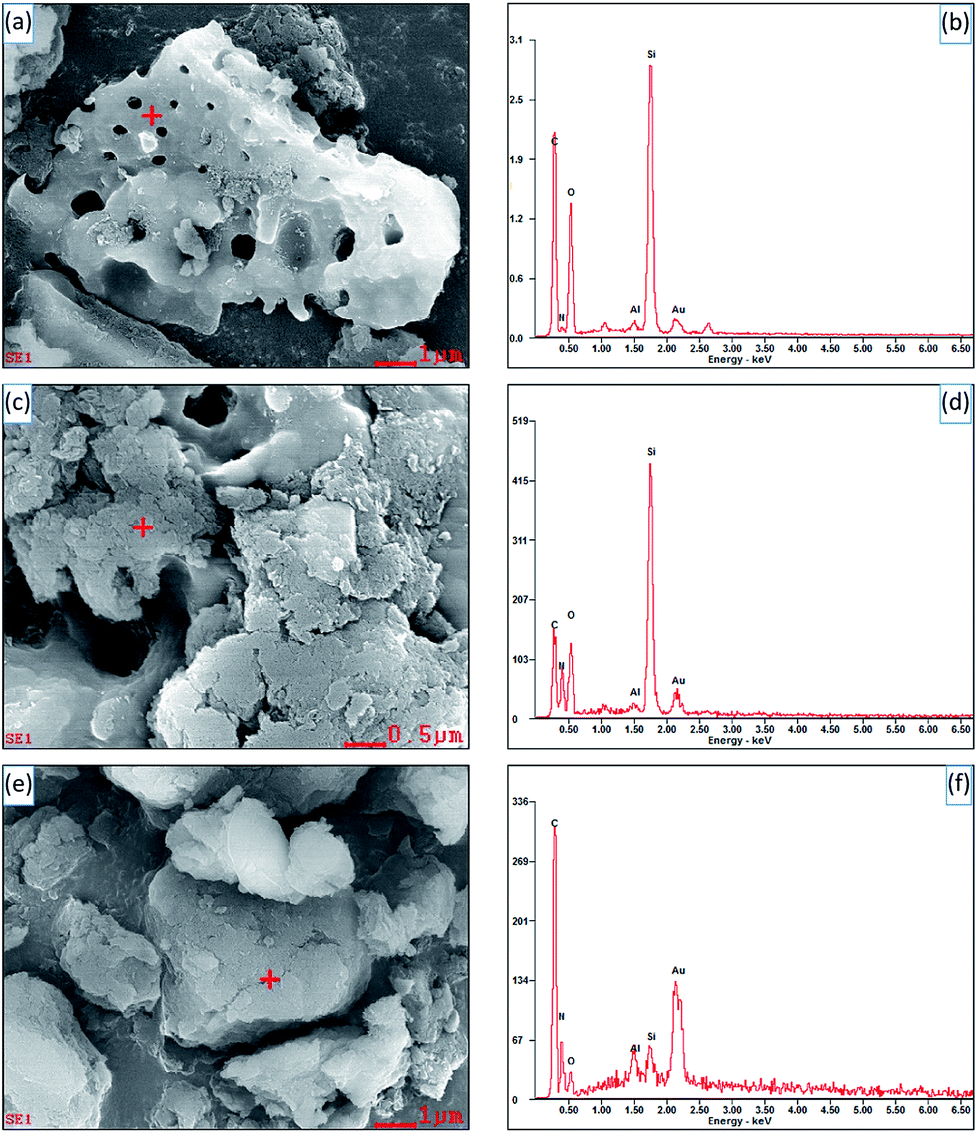 | ||
| Fig. 3 SEM images and EDS spectra of diatomite (a and b), hybrid S5 (c and d) and S15 (e and f). | ||
Fig. 4 shows the TEM photographs of SCN and hybrid S15. As shown, the SCN displays the thin sheet shape with porous structure (Fig. 4a). For hybrid S15, two kinds of structure can be observed: thin sheet structure of SCN and the structure with sharp edge and enormous size, as shown in Fig. 4b. In the experiment, the diatomite may be broken into small blocks and presents a sharp edge. Therefore, the structures with sharp edge and enormous size may be the characteristics of diatomite in the hybrids. Furthermore, it can be seen the thin sheet structure of SCN are wrapped on the surface of diatomite, which is consistent with the experimental results of SEM.
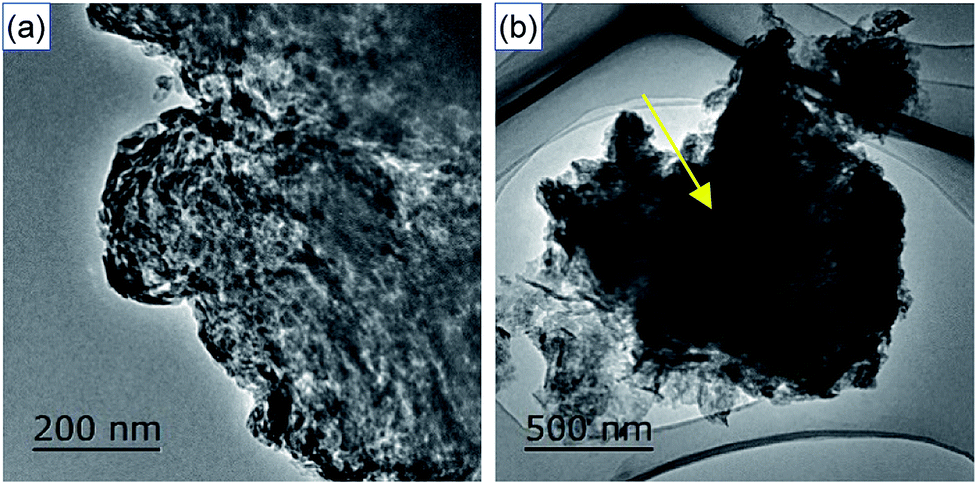 | ||
| Fig. 4 TEM images of SCN (a) and as-prepared hybrid S15 (b). | ||
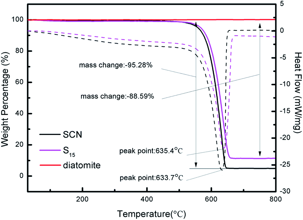
Fig. 5 displays the TG-DSC curves of diatomite, SCN and as-prepared hybrid S15. As it can be seen, the mass of diatomite remains unchanged throughout the whole heating process because of its good physical stability and favourable chemical inertness. However, the mass of SCN and hybrid S15 begins to decrease at 450 °C. From 30 °C to 800 °C, the mass loss of SCN is about 95.28%. For hybrid S15, it has an 88.59% mass loss, which is slightly below that of pure SCN. It implies the hybrid S15 contains about 88.59% of SCN. Considering the combustion residues of SCN, the diatomite content in hybrid S15 is very close to the theoretical calculation value of diatomite mass fraction (6.25%) in the hybrid. Moreover, the decomposition temperature of g-C3N4 shifts from 633.7 °C in SCN to 635.4 °C in hybrid, indicating there is a strong interaction role between g-C3N4 and diatomite. Nevertheless, the pure g-C3N4 should have a 100% mass loss at about 600 °C in the air, which has been verified in some ref. 4, 14 and 43. In this experiment, the remained residues of SCN after the heating process may come from the impurities.
 | ||
| Fig. 5 TG-DSC curves of diatomite, SCN and as-prepared hybrid S15. | ||
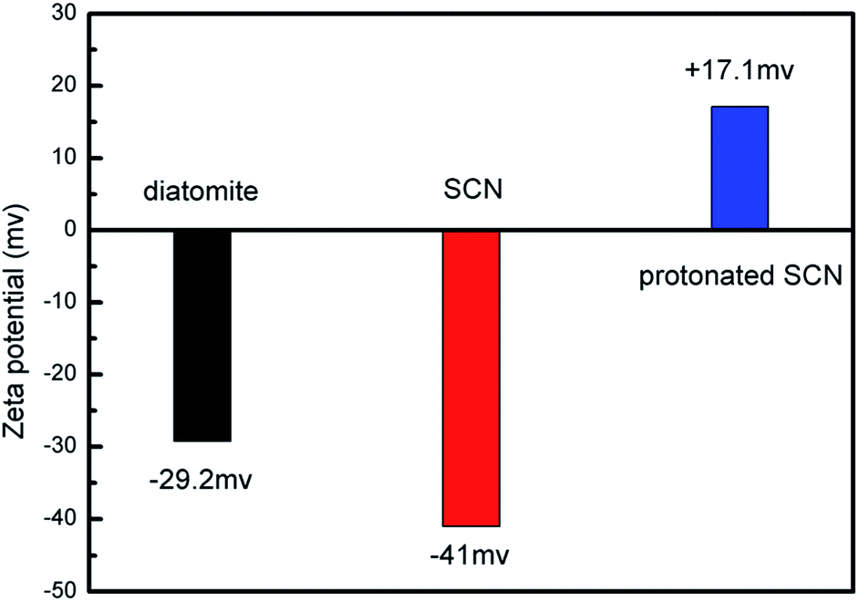
Based on the above microstructure analysis, the schematic diagram for the synthesis process of g-C3N4/diatomite hybrid is shown in Scheme 1. At first, g-C3N4 bulks were thermal exfoliated to SCN which possess a large specific surface area.4,14 Afterwards, the SCN was treated with hydrochloric acid to obtain the surface with positive charges due to the presence of H+.14,19 On the contrary, under the conditions of experiment, the surface of diatomite was negative charged because of the hydrolysis of silicon hydroxyl.40 The surface charge characteristics of SCN, protonated SCN and diatomite are shown in Fig. 6. It is observed the zeta potential values of protonated SCN and diatomite are +17.1 mV and −29.2 mV. As a result, the two components may be self-assembled through the electrostatic adsorption. Especially, the excellent adsorptive ability of diatomite may greatly accelerate this process and strengthen the interaction role between SCN and diatomite. Finally, the calcination process may further enhance the bonding force and form a stable structure. Furthermore, with the increase of SCN content in hybrids, the surface of diatomite is gradually covered by SCN. The zeta potential values for the hybrids S5, S10, S15, S20 were tested as −26.48 mV, −24.09 mV, −23.99 mV and −23.29 mV, respectively. They are all between the potentials of diatomite and protonated SCN, which may be attributed to the partial recovery of protonation by subsequent calcination process.44
 | ||
| Scheme 1 Synthesis process of g-C3N4/diatomite hybrids. | ||
 | ||
| Fig. 6 Zeta potential of diatomite, SCN and protonated SCN. | ||
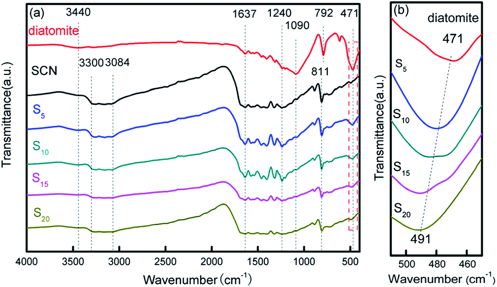
The structural information of diatomite, SCN and as-prepared hybrids was further analysed using FTIR spectra in Fig. 7. From Fig. 7a, it can be observed that all the samples show an absorption peak at 3440 cm−1 which can be assigned to the stretching vibration of adsorbed water in the air.40,45,46 For diatomite, the peaks at 1090, 792 and 471 cm−1 are derived from the stretching vibration of Si–O–Si.40 FTIR spectrum of SCN demonstrates several strong absorption bands in the range of 1240–1637 cm−1, which may be attributed to the skeletal stretching of CN heterocycles with peaks centred at 1240, 1322, 1404, 1461, 1573 and 1637 cm−1. The sharp absorption peak positioned at 811 cm−1 is related to the characteristic absorption peak of tri-s-triazine units,43,46 while the broad absorption band in the region of 3084–3300 cm−1 is originated from the stretching vibration modes of N–H.19 After the immobilization of SCN on the surface of diatomite, the as-formed hybrids present all the characteristic absorption peaks of diatomite and SCN. Notably, the characteristic peak at 471 cm−1 in bare diatomite illustrates a shift to 491 cm−1 in hybrids with the increase of SCN content, as shown in Fig. 7b, suggesting there is a strong interaction role between SCN and diatomite, which is consistent with the above analysis results of SEM and TEM.
 | ||
| Fig. 7 FTIR patterns of diatomite, SCN and as-prepared hybrids (a) and partial enlarged patterns from 450–510 cm−1 (b). | ||
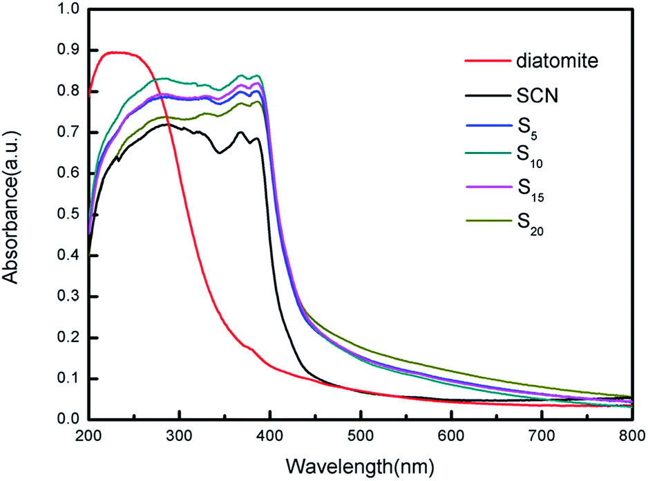
The optical absorption properties of diatomite, SCN and as-prepared hybrids were characterized using UV/Vis diffuse reflectance spectroscopy, as shown in Fig. 8. Interestingly, the adsorption edge of as-prepared hybrids exhibit an obvious redshift as compared to that of pure diatomite and SCN. This may be caused by the calcination process, during which the molar ratio of N to C has changed from 1.667 to 1.639 according to the calculation of the subsequent XPS analysis. Note that bare diatomite has a little visible light absorption ranging from 400 nm to 800 nm, while the visible absorption onset of SCN is located at approximately 437 nm. Furthermore, the hybrids also demonstrate the broader visible light absorption tail and stronger visible light absorption ability than that of bare SCN. In visible light region, hybrid S20 clearly exhibits the highest absorbance, while the absorbance curves of different hybrids varies slightly due to their relatively similar proportion of different ingredients. More importantly, the whole curves of as-prepared hybrids are smooth and no characteristic absorption of bare diatomite and SCN is observed, indicating diatomite and SCN in the hybrids forms a stable structure instead of mechanical mixing.
 | ||
| Fig. 8 UV-vis diffuse reflectance spectra of diatomite, SCN and as-prepared hybrids. | ||
The XPS analysis was further conducted to investigate the chemical composition state of SCN and as-prepared hybrid S15 in Fig. 9. The survey scans of SCN and the hybrid S15 are shown in Fig. 9a and b, respectively. The high-resolution spectra of C1s and N1s are demonstrated in Fig. 9c and d. Calibration was carried out using the reference of C1s 284.6 eV, which was regarded as the free carbon or carbon contamination.47,48 Compared to the survey scan of SCN (Fig. 9a), the element Si is only observed in the XPS spectrum of hybrid S15. The peaks are very weak and hardly to be identified even in the high magnification (Fig. 9b), which may be due to that the diatomite is closely wrapped by SCN in hybrid S15. The high-resolution XPS spectra of C1s of SCN (Fig. 9c) displays an obvious peak centered at 287.3 eV which can be assigned to the N–C![[double bond, length as m-dash]](https://www.rsc.org/images/entities/char_e001.gif) N.48 For hybrid S15, this peak shifts to 287.5 eV. The high-resolution XPS spectra of N1s in Fig. 9d shows three different peaks centered around 397.8 eV, 399.7 eV and 403.5 eV, which are derived from the sp2-hybridized nitrogen of N–CN, the tertiary nitrogen of N–(C)3, and the π-excitation in the C–N groups, respectively.49–51 In the terms of N1s in the hybrid S15, the corresponding peaks shift to 398.0 eV, 400.2 eV and 403.6 eV, which may be attributed to the interaction role of SCN and diatomite.
N.48 For hybrid S15, this peak shifts to 287.5 eV. The high-resolution XPS spectra of N1s in Fig. 9d shows three different peaks centered around 397.8 eV, 399.7 eV and 403.5 eV, which are derived from the sp2-hybridized nitrogen of N–CN, the tertiary nitrogen of N–(C)3, and the π-excitation in the C–N groups, respectively.49–51 In the terms of N1s in the hybrid S15, the corresponding peaks shift to 398.0 eV, 400.2 eV and 403.6 eV, which may be attributed to the interaction role of SCN and diatomite.
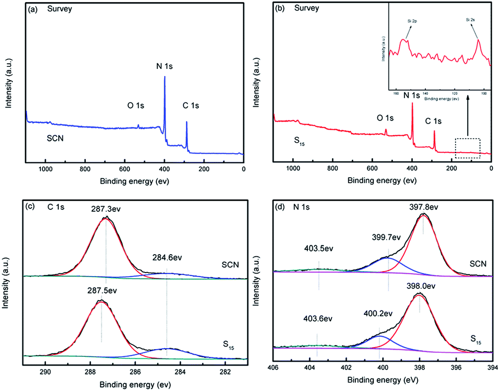 | ||
| Fig. 9 XPS spectra of SCN and as-prepared hybrid S15. Survey scan of the hybrid S15 (a), survey scan of SCN (b), C1s of the hybrid S15 and SCN (c), N1s of the hybrid S15 and SCN (d). | ||
Photocatalytic degradation of model pollutants over different photocatalysts were evaluated under visible light irradiation (λ > 400 nm). As a contrast, g-C3N4 bulks were also used as photocatalyst. Fig. 10a and b show the curves of MO concentration and degradation rate over time in the degradation process, respectively. In the first 30 min of the experiment before irradiation, the MO concentration decreases due to the adsorption of photocatalysts. In all cases, the hybrids demonstrate the higher adsorption ability compared with bulk g-C3N4 and SCN, implying the addition of diatomite significantly increases the adsorption ability of hybrids. The specific surface areas of SCN, diatomite and hybrid S15 have been detected as 227.82 m2 g−1, 44.82 m2 g−1 and 139.02 m2 g−1, respectively. From the MO molecules adsorption results, it can be inferred that the specific surface area is not the only factor influencing the adsorption ability of photocatalysts. The pore size and its distribution, as well as the hydrophilicity and hydrophobicity of the adsorbate are the other important factors.
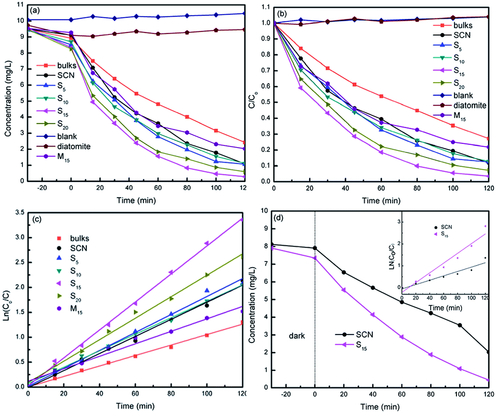 | ||
| Fig. 10 Concentration change of MO (a) and degradation efficiency of MO (b) during photocatalytic degradation. Linear transform ln(C0/C) of the kinetic curves of MO degradation (c), the photocatalytic degradation of phenol (d) and the inset is the linear transform ln(C0/C) of the kinetic curves of phenol degradation. | ||
On the other hand, all the hybrids present the higher photocatalytic degradation rate than that of bulk g-C3N4 and SCN, as shown in Fig. 10b. The highest degradation rate of MO is obtained for hybrid S15 and reaches 97% in 120 min. The kinetic degradation curves over different photocatalysts were further analysed in Fig. 10c. As can be seen from this figure, the hybrid S15 possesses the highest degradation rate constant of 0.028 min−1, which is 2.55 times of g-C3N4 bulks (0.011 min−1), 2.15 times of M15 (0.013 min−1) and 1.65 times of SCN (0.017 min−1). Compared with g-C3N4 bulks, SCN shows the higher photocatalytic activity for MO degradation due to its large specific surface area. It is worth noting that the performance of M15 is slightly worse than that of pure SCN, but it is much worse than the performance of S15. It may be due to the fact that the amount of active ingredient g-C3N4 in M15 is slightly less than that of pure SCN. Moreover, M15 is a kind of mechanical mixture. The interaction role of SCN and diatomite is very weak. In contrast to the hybrid S15, M15 shows the lower adsorption ability. The MO molecules adsorbed on the surface of diatomite may hardly diffuse to the active sites of SCN. Thus, the synergistic effect of adsorption and photocatalysis is not observed. The experimental results clearly demonstrate the difference between as-prepared hybrids and mechanical mixture. For comparison, the phenol solution was also used as colourless pollutant model. The degradation curves of phenol over SCN and hybrid S15 is demonstrated in Fig. 10d. Similar as MO degradation, the hybrid S15 simultaneously shows the higher adsorption and degradation rate of phenol than that of SCN. At 120 min illumination, the removal rate of phenol over hybrid S15 reaches 94%. The degradation rate constant of phenol over hybrid S15 (0.022 min−1) is 2.2 times of SCN (0.01 min−1).
Considering that only a small amount of diatomite without photocatalytic activity was added into SCN, the photocatalytic performance of the hybrids has been obviously improved. In fact, for one thing, compared with pure SCN, the amount of active ingredient in the hybrids with the same mass is reduced. For another thing, diatomite is inexpensive and easily to be obtained. Thus, the results clearly demonstrate the advantages for the immobilization of g-C3N4 nanosheets on diatomite.
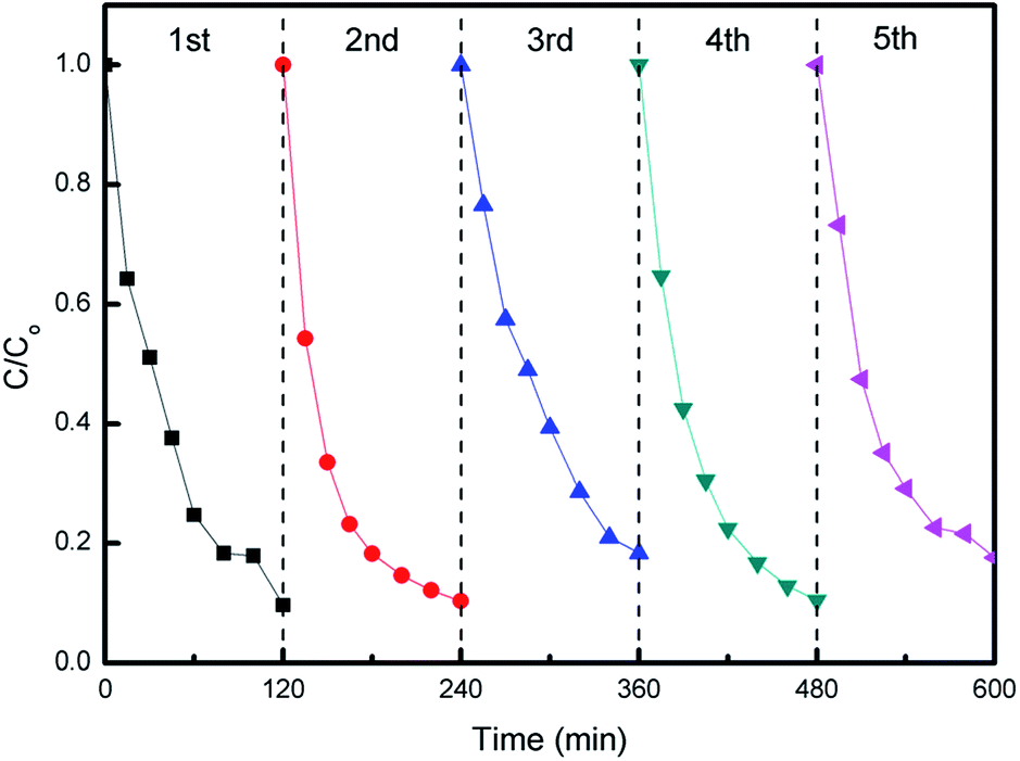
The photocatalytic stability of hybrid S15 was evaluated by recycling tests of MO degradation. As can be seen from Fig. 11, the hybrid S15 remains a relative stable MO degradation efficiency in each cycle. The slight data fluctuations for MO degradation may be due to a small quantity of photocatalysts mass loss. After five cycles, the hybrid S15 still exhibits the high MO degradation efficiency, indicating a good photocatalytic stability and a potential for practical environment applications.
 | ||
| Fig. 11 Cycling tests of MO degradation over hybrid S15 under visible light irradiation. | ||
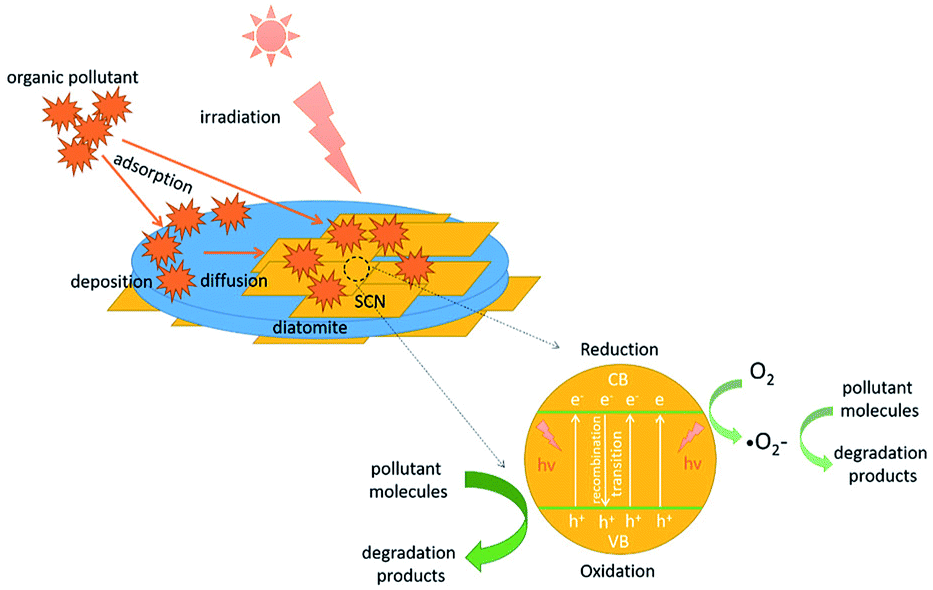
To explain this enhanced photocatalytic activity, the photocatalytic mechanism over the hybrids was proposed in Scheme 2. Under the visible light irradiation, the holes (h+) and electrons (e−) will be generated at first in the conduction band (CB) and the valence band (VB) of g-C3N4. Subsequently, these photoinduced electrons and holes will transfer to the surface of hybrids. In this migration process, the electrons and holes will recombine or separate. Those separated photoinduced electrons can form the superoxide radical anions (·O2−) on or around the surface of g-C3N4 through a series of reaction. Both ·O2− and separated holes (h+) have the superior oxidation power to degrade the surface adsorbed pollutant molecules to CO2 and H2O. In this experiment, it has been confirmed that the hybrids possess the enhanced visible light absorption ability compared with the bare SCN. Therefore, more electrons and holes will be excited in the hybrids than that of SCN. In another situation, the as-prepared g-C3N4/diatomite hybrids show the higher adsorption capacity than pure SCN and diatomite. During the photocatalytic reaction, many pollutant molecules will be first adsorbed on the surface of hybrids. With the enrichment of surface adsorbed pollutant molecules, the pollutant molecules will be easily diffused to the active sites of g-C3N4. The as-produced oxidative species in the hybrids, such as h+ and ·O2− will be consumed rapidly, which in turn accelerate the separation efficiency of photoinduced electrons and holes. As a result, the adsorption ability of the hybrids has a great contribution to the enhanced photocatalytic activity. The experiment results demonstrate the synergistic effect of adsorption-degradation on the photocatalytic process over the hybrids.9,35,36 However, the adsorption and photocatalysis is mutual restraint with each other. If the adsorption ability of hybrids is strong, the organic molecules may cover the surface of photocatalysts and its active sites, which in turn affect the photocatalytic efficiency. For the hybrid S20, it exhibits a little higher absorption in visible light region than S15. However, its photocatalytic activity is a slightly lower than S15. It may be attributed to its stronger adsorption ability for organic molecules (shown in Fig. 10a), which results in the extensive coverage of active sites. As a result, the photocatalytic activity of S20 slightly decreases.
 | ||
| Scheme 2 Proposed photocatalytic mechanism over the hybrids. | ||
Conclusions
In summary, we have demonstrated a facile method for the immobilization of g-C3N4 nanosheets on the surface of diatomite to enhance the adsorption ability and photocatalytic performance of bare g-C3N4 nanosheets. The hydrochloric acid pre-treatment resulted in a positive charged surface of g-C3N4 nanosheets, which was beneficial for the interaction role with negative charged surface of diatomite due to the hydrolysis of silicon hydroxyl. The subsequent calcination process further enhanced this interaction role, which was confirmed by the FESEM, TEM, FTIR, DRS and XPS studies. The as-prepared hybrids revealed a high visible light absorption and utilization compared to bare g-C3N4 nanosheets and diatomite. The photocatalytic results for MO and phenol degradation indicated the hybrids with the mass ratio of g-C3N4 nanosheets to diatomite 15:1 presented the highest degradation constant, which can be ascribed to the strong interaction role between g-C3N4 nanosheets and diatomite, and the adsorption/photocatalysis synergistic effect. This work provides a novel method to immobilize the newly developed visible-light driven photocatalyst (g-C3N4) on the surface of the conventional adsorbent (diatomite). It is expected that the hybrid can be applied in various applications, including catalysis, energy storage and conversion.
Conflicts of interest
There are no conflicts to declare.Acknowledgements
This work was supported by the Research Project of Hubei Provincial Department of Education (D20171405), the Natural Science Foundation of Hubei Province of China (2013CFA085), and the International Science & Technology Cooperation Program of China (2016YFE0124300).Notes and references
- M. A. Shannon, P. W. Bohn, M. Elimelech, B. J. Mariñas and A. M. Mayes, Nature, 2008, 452, 301–310 CrossRef PubMed.
- A. Fujishima and K. Honda, Nature, 1972, 238, 37–38 CrossRef PubMed.
- X. C. Wang, K. Maeda, A. Thomas, K. Takanabe, G. Xin, J. M. Carlsson, K. Domen and M. Antonietti, Nat. Mater., 2009, 8, 76–80 CrossRef PubMed.
- S. W. Cao, J. X. Low, J. G. Yu and M. Jaroniec, Adv. Mater., 2015, 27, 2150–2176 CrossRef PubMed.
- S. Ye, L. G. Qiu, Y. P. Yuan, Y. J. Zhu, J. Xia and J. F. Zhu, J. Mater. Chem. A, 2013, 1, 3008–3015 RSC.
- C. S. Pan, J. Xu, Y. J. Wang, D. Li and Y. F. Zhu, Adv. Funct. Mater., 2012, 22, 1518–1524 CrossRef.
- Y. P. Zang, L. P. Li, X. G. Li, R. Lin and G. S. Li, Chem. Eng. J., 2014, 246, 277–286 CrossRef.
- F. F. Liang and Y. F. Zhu, Appl. Catal., B, 2016, 180, 324–329 CrossRef.
- M. Zhang, W. J. Jiang, D. Liu, J. Wang, Y. F. Liu, Y. Y. Zhu and Y. F. Zhu, Appl. Catal., B, 2016, 183, 263–268 CrossRef.
- J. Xu, L. W. Zhang, R. Shi and Y. F. Zhu, J. Mater. Chem. A, 2013, 1, 14766–14772 RSC.
- Y. F. Li, R. X. Jin, Y. Xing, J. Q. Li, S. Y. Song, X. C. Liu, M. Li and R. C. Jin, Adv. Energy Mater., 2016, 6, 1601273 CrossRef.
- R. C. Pawar, S. Kang, J. H. Park, J. H. Kim, S. Ahn and C. S. Lee, Sci. Rep., 2016, 6, 31147 CrossRef PubMed.
- X. J. Bai, S. C. Yan, L. Wang, W. J. Jiang, S. L. Wu, C. P. Sun and Y. F. Zhu, J. Mater. Chem. A, 2014, 2, 17521–17529 RSC.
- W. J. Jiang, W. J. Luo, J. Wang, M. Zhang and Y. F. Zhu, J. Photochem. Photobiol., C, 2016, 28, 87–115 CrossRef.
- C. Wang, W. S. Zhu, Y. H. Xu, H. Xu, M. Zhang, Y. H. Chao, S. Yin, H. M. Li and J. G. Guo, Ceram. Int., 2014, 40, 11627–11635 CrossRef.
- Y. P. Li, L. Y. Huang, J. B. Xu, H. Xu, Y. G. Xu, J. X. Xia and H. M. Li, Mater. Res. Bull., 2015, 70, 500–505 CrossRef.
- M. Wang, P. Ju, Y. Zhao, J. J. Li, X. X. Han and Z. M. Hao, New J. Chem., 2018, 42, 910–917 RSC.
- H. An, B. Lin, C. Xue, X. Q. Yan, Y. Z. Dai, J. J. Wei and G. D. Yang, Chin. J. Catal., 2018, 39, 654–663 CrossRef.
- W. J. Ong, L. L. Tan, S. P. Chai, S. T. Yong and A. R. Mohamed, Nano Energy, 2015, 13, 757–770 CrossRef.
- Z. L. Fang, H. F. Rong, L. Y. Zhou and Q. Pang, J. Mater. Sci., 2015, 50, 3057–3064 CrossRef.
- S. Z. Wu, K. Li and W. D. Zhang, Appl. Surf. Sci., 2015, 324, 324–331 CrossRef.
- Y. F. Li, R. X. Jin, X. Fang, Y. Yang, M. Yang, X. C. Liu, Y. Xing and S. Y. Song, J. Hazard. Mater., 2016, 313, 219–228 CrossRef PubMed.
- Y. F. Li, K. Li, Y. Yang, L. J. Li, Y. Xing, S. Y. Song, R. C. Jin and M. Li, Chem.–Eur. J., 2015, 21, 7739–17747 Search PubMed.
- J. Cao, Y. J. Zhao, H. L. Lin, B. Y. Xu and S. F. Chen, Mater. Res. Bull., 2013, 48, 3873–3880 CrossRef.
- D. L. Peng, H. H. Wang, K. Yu, Y. Chang, X. G. Ma and S. J. Dong, RSC Adv., 2016, 6, 77760–77767 RSC.
- M. Faisal, A. A. Ismail, F. A. Harraz, S. A. Al-Sayari, A. M. El-Toni and M. S. Al-Assiri, Mater. Des., 2016, 98, 223–230 CrossRef.
- J. J. Wang, L. Tang, G. M. Zeng, Y. N. Liu, Y. Y. Zhou, Y. C. Deng, J. J. Wang and B. Peng, ACS Sustainable Chem. Eng., 2017, 5, 1062–1072 CrossRef.
- W. J. Jiang, W. J. Luo, R. L. Zong, W. Q. Yao, Z. P. Li and Y. F. Zhu, Small, 2016, 12, 4370–4378 CrossRef PubMed.
- Z. W. Tong, D. Yang, J. F. Shi, Y. H. Nan, Y. Y. Sun and Z. Y. Jiang, ACS Appl. Mater. Interfaces, 2015, 7, 25693–25701 CrossRef PubMed.
- F. Dong, Z. Y. Wang, Y. H. Li, W. K. Ho and S. C. Lee, Environ. Sci. Technol., 2014, 48, 10345–10353 CrossRef PubMed.
- M. Zhang, J. Xu, R. L. Zong and Y. F. Zhu, Appl. Catal., B, 2014, 147, 229–235 CrossRef.
- X. W. Wu, Z. J. Zhang, C. Xia, B. Q. Chen, X. Z. Jin, Z. H. Huang, Y. G. Liu, M. H. Fang and X. Min, J. Alloys Compd., 2017, 718, 15–21 CrossRef.
- Y. Al-Degs, M. A. M. Khraisheh and M. F. Tutunji, Water Res., 2001, 35, 3724–3728 CrossRef PubMed.
- W. B. Yu, L. L. Deng, P. Yuan, D. Liu, W. W. Yuan, P. Liu, H. P. He, Z. H. Li and F. R. Chen, J. Colloid Interface Sci., 2015, 448, 545–552 CrossRef PubMed.
- Y. Kuwahara and H. Yamashita, J. Mater. Chem., 2011, 21, 2407–2416 RSC.
- Z. M. Sun, C. Q. Li, G. Y. Yao and S. L. Zheng, Mater. Des., 2016, 94, 403–409 CrossRef.
- P. Tanniratt, T. Wasanapiarnpong, C. Mongkolkachit and P. Sujaridworakun, Ceram. Int., 2016, 42, 17605–17609 CrossRef.
- B. Wang, G. X. Zhang, X. Leng, Z. M. Sun and S. L. Zheng, J. Hazard. Mater., 2015, 285, 212–220 CrossRef PubMed.
- P. Niu, L. L. Zhang, G. Liu and H. M. Cheng, Adv. Funct. Mater., 2012, 22, 4763–4770 CrossRef.
- Z. M. Sun, X. P. Yang, G. X. Zhang, S. L. Zheng and R. L. Frost, Int. J. Miner. Process., 2013, 125, 18–26 CrossRef.
- F. Dong, L. W. Wu, Y. J. Sun, M. Fu, Z. B. Wu and S. C. Lee, J. Mater. Chem. C, 2011, 21, 15171–15174 RSC.
- X. Y. Wang, H. H. Wang, K. Yu and X. F. Hu, Mater. Res. Bull., 2018, 97, 306–313 CrossRef.
- J. G. Yu, S. H. Wang, J. X. Low and W. Xiao, Phys. Chem. Chem. Phys., 2013, 15, 16883–16890 RSC.
- Y. J. Zhang, A. Thomas, M. Antonietti and X. C. Wang, J. Am. Chem. Soc., 2009, 131, 50–51 CrossRef PubMed.
- P. Yuan, D. Liu, D. Y. Tan, K. K. Liu, H. G. Yu, Y. H. Zhong, A. H. Yuan, W. B. Yu and H. P. He, Microporous Mesoporous Mater., 2013, 170, 9–19 CrossRef.
- Y. Bai, P. Q. Wang, J. Y. Liu and X. J. Liu, RSC Adv., 2014, 4, 19456–19461 RSC.
- Y. P. Li, J. Zhan, L. Y. Huang, H. Xu, H. M. Li, R. X. Zhang and S. L. Wu, RSC Adv., 2014, 4, 11831–11839 RSC.
- W. Li, C. Li, B. Chen, X. L. Jiao and D. R. Chen, RSC Adv., 2015, 5, 34281–34291 RSC.
- H. Liu, Z. T. Jin and Z. Z. Xu, Dalton Trans., 2015, 44, 14368–14375 RSC.
- J. L. Cao, C. Qin, Y. Wang, H. L. Zhang, B. Zhang, Y. X. Gong, X. D. Wang, G. Sun, H. Balac and Z. Y. Zhang, RSC Adv., 2017, 7, 25504–25511 RSC.
- J. T. Gao, Y. Wang, S. J. Zhou, W. Lin and Y. Kong, Chemcatchem, 2017, 9, 1708–1715 CrossRef.
| This journal is © The Royal Society of Chemistry 2018 |