
 Open Access Article
 This Open Access Article is licensed under a Creative Commons Attribution-Non Commercial 3.0 Unported Licence
Vinyltriethoxysilane crosslinked poly(acrylic acid sodium) as a polymeric binder for high performance silicon anodes in lithium ion batteries†
Xiangyu Zeng,
Yongji Shi,
Yu Zhang,
Ruixian Tang and
Liangming Wei *
*
Key Laboratory for Thin Film and Microfabrication of the Ministry of Education, Department of Microelectronics and Nanoscience, School of Electronic Information and Electrical Engineering, Shanghai Jiao Tong University, 800 Dongchuan Road, Shanghai, 200240, China. E-mail: lmwei@sjtu.edu.cn; Fax: +86-21-34205665; Tel: +86-21-34205665
First published on 17th August 2018
Abstract
In order to effectively relieve the large volume changes of silicon anodes during the cycling process in lithium ion batteries (LIBs), we developed a vinyltriethoxysilane crosslinked poly(acrylic acid sodium) polymeric binder (PVTES-NaPAA) for the Si anodes. The PVTES-NaPAA binder was synthesized by using a free radical co-polymerization method with VTES and NaPAA as precursors. In this binder, NaPAA with carboxyl groups can provide strong adhesion between Si particles and the current collector. Furthermore, VTES can be hydrolyzed and condense with each other to form a three-dimensional crosslinked network; the special network makes it possible to improve the Si electrode stability, resulting in an excellent cycling performance (78.2% capacity retention after 100 cycles) and high coulombic efficiency (99.9% after 100 cycles).
1. Introduction
Nowadays, lithium-ion batteries are applied in various aspects in our life.1 As with the anode materials concerned, materials with high storage capacities have attracted tremendous interest in research.2–5 Among these materials, silicon (Si) materials process high theoretical capacity (4200 mA h g−1), which is 11 times larger than that of the commercial graphite (372 mA h g−1).6–8 Therefore, silicon has great potential to be the candidate of lithium-ion battery anode materials. However, the huge volume changes (∼300%) of Si materials during the cycling process usually lead to electrical deactivation and fast capacity fading.9–12 To solve the problem, great efforts have been made including synthesising Si-based composites, preparing novel Si nanomaterials, designing Si crystal materials with special shapes, etc.13–16 As a part of the lithium battery material composition, the binder also has great influence on the cycle performance. Many researchers have prepared polymeric binders that can improve the cycle performance of electrode materials.17–20Polymeric binders are usually used to bond the active material of the electrode with the conductive agent and the metal current collector. The properties of polymeric binders can directly affect the cycle stability and capacity of the lithium-ion batteries. With respect to Si anodes of the lithium-ion batteries, the polymeric binders should effectively accommodate the expansion of the silicon material during the charge–discharge process.21–23 Nowadays, poly(vinylidene fluoride) (PVDF) is one of the most widely used polymeric binders for Si anodes in the industry, but its poor adhesion with Si particles usually leads to bad cycle performance.24 In comparison of binders, a large number of studies shows that carboxymethyl cellulose (CMC)25 and poly(acrylic acid) (PAA)20 are more effective binders to improve the capacity retention due to their carboxyl and hydroxyl groups. The ester bonding and hydrogen bonding can enhance the bond between the polymeric binders and the active materials, and further improve the cycling stability of the battery.25–27 However, the demerits of these binders include weak mechanical properties and electrode cracking during cycling. Considering the defects of those binders, functionalizing these common binders by grafting, crosslinking or blend can make it possible to improve the interaction between polymeric binders and silicon particles. For example, the crosslinked PAA functionalized with benzophenone group, crosslinked PAA and PVA, PAA-grafted CMC all significantly enhanced the electrochemical performance of Si-based LIBs.28–32 However, the synthesize process of the polymeric binders is intricate and complex, a simple and effective polymeric binder system is required in LIBs.
Organofunctional silanes are important processing agents to improve the adhesive strength, mainly used as polymer composite additives.33 Vinyltriethoxysilane (VTES) is one of the most well-known organofunctional silanes, which possess excellent flexibility and adhesive properties.34–36 Herein, we develop a VTES crosslinked NaPAA polymer (PVTES-NaPAA) as the polymeric binder for silicon anodes in lithium ion batteries. The synthesis of the polymer is through free radical co-polymerization method with VTES and acrylic acid monomer as the precursor. The PVTES-NaPAA polymeric binder can effectively improve the cycle stability of Si anodes and exhibit a high coulombic efficiency. Furthermore, the Si anodes with PVTES-NaPAA as the binder can also form a stable SEI film on the electrode surface during cycling.
2. Experimental
2.1 Materials
The Si nanoparticles (50–100 nm) and the vinyltriethoxysilane (VTES) were obtained from Alfa Aesar. The lithium-foil and electrolyte were obtained from Shanghai Xiaoyuan Co. The initiator (ammonium peroxydisulfate) and other chemicals were purchased from Sinopharm Reagent Co.2.2 PVTES-NaPAA preparation
Firstly, 0.2 g VTES and 4 mL acrylic acid monomer were dissolved in 80 mL distilled water. Secondly, the solution was moved into a 250 mL three-necked flask and the nitrogen was used to remove the oxygen in the solution for 6 h. Thirdly, 0.1 g of the initiator was added into the solution. Then the solution was mechanical stirred for 4 h at 60 °C to prepare the PVTES-NaPAA polymeric binder. The entire process keep nitrogen gas environment. Finally, the sodium hydroxide was used to neutralize the PVTES-NaPAA to pH 6.2.3 Electrochemical experiments
The electrochemical performance was tested by using CR2016 type half coin cells. The composition of the working electrodes includes Si nanoparticles, conductive carbon (Super P) and polymeric binders with 6![[thin space (1/6-em)]](https://www.rsc.org/images/entities/char_2009.gif) :2:2 weight ratio. The mass loading on the electrodes is about 0.5–1.3 mg cm−2. The lithium metal foil and the glass microfibre filter polymer were used as the counter electrode and the separator, respectively. The ethylene carbonate (EC) and dimethyl carbonate (DMC) (volume ratio 1:1) with 10 wt% fluoroethylene carbonate (FEC) were mixed together as the Si-based anode electrolyte with LiPF6 (1 M) dissolved in it. The cyclic voltammetry (CV) curve was tested by CHI 760E electrochemical workstation (Chenhua Instruments Co., Shanghai, China). The testing voltage ranged from 0.01 V to 1.2 V. The cycling performance and rate capability were tested using the battery test system (LAND, Wuhan, China).
:2:2 weight ratio. The mass loading on the electrodes is about 0.5–1.3 mg cm−2. The lithium metal foil and the glass microfibre filter polymer were used as the counter electrode and the separator, respectively. The ethylene carbonate (EC) and dimethyl carbonate (DMC) (volume ratio 1:1) with 10 wt% fluoroethylene carbonate (FEC) were mixed together as the Si-based anode electrolyte with LiPF6 (1 M) dissolved in it. The cyclic voltammetry (CV) curve was tested by CHI 760E electrochemical workstation (Chenhua Instruments Co., Shanghai, China). The testing voltage ranged from 0.01 V to 1.2 V. The cycling performance and rate capability were tested using the battery test system (LAND, Wuhan, China).
2.4 Characterization methods
The morphologies of the electrodes with binders were analyzed by using field-emission scanning electron microscopy (FE-SEM, Carl Zeiss Ultra 55). The crosslinked process was measured by using Fourier transform infrared (FTIR, Perkin-Elmer 70) spectroscopy with KBr pieces. The 180° peel experiments and the tensile tests were carried out using the high-precision material mechanics test instrument (Hengyi Testing Machine Co., Shanghai, China).3. Results and discussion
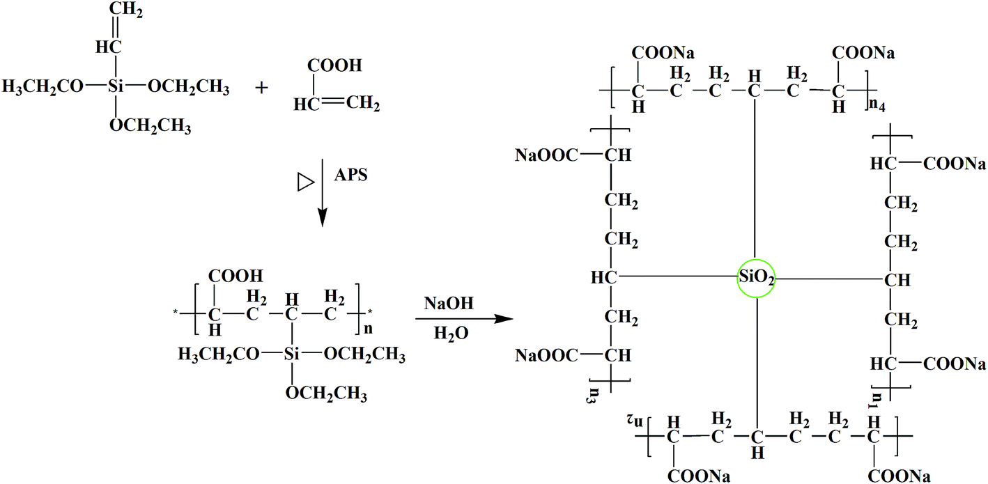
The PVTES-NaPAA binder was synthesized by using VTES and acrylic acid monomer as the precursor and ammonium persulfate as the initiator via a free radical co-polymerization process. The synthetic process of the PVTES-NaPAA polymeric binder is shown in Scheme 1. After heating, the initiator (ammonium peroxydisulfate) decomposed to generate anionic radical, which initiated co-polymerization of VTES and acrylic acid monomer. To confirm the copolymerization of the VTES and NaPAA, FT-IR spectra of PVTES-NaPAA, VTES and NaPAA were tested as shown in Fig. 1a. After polymerization, the absorption bands at 1160–1100 cm−1 (correspond to Si–O from VTES)35 and 1571, 1452 cm−1 (correspond to C![[double bond, length as m-dash]](https://www.rsc.org/images/entities/char_e001.gif) O in NaPAA)37 can be observed in PVTES-NaPAA. Furthermore, the absorption bands at 3064 cm−1 (correspond to CC–H from VTES) disappeared.38 These results evidenced the successful formation of PVTES-NaPAA polymer. The 1H NMR spectrum of PVTES-NaPAA (Fig. 1d) shows alkane (–CH2–CH–) in PVTES and NaPAA (1.25–2.5 ppm), methyl group (1.08 ppm) and methylene group (3.55 ppm) in VTES. These results are consistent with the FT-IR spectra, which evidence successful copolymerization of VTES and NaPAA.
O in NaPAA)37 can be observed in PVTES-NaPAA. Furthermore, the absorption bands at 3064 cm−1 (correspond to CC–H from VTES) disappeared.38 These results evidenced the successful formation of PVTES-NaPAA polymer. The 1H NMR spectrum of PVTES-NaPAA (Fig. 1d) shows alkane (–CH2–CH–) in PVTES and NaPAA (1.25–2.5 ppm), methyl group (1.08 ppm) and methylene group (3.55 ppm) in VTES. These results are consistent with the FT-IR spectra, which evidence successful copolymerization of VTES and NaPAA.
 | ||
| Scheme 1 The synthetic process of the PVTES-NaPAA binder. | ||
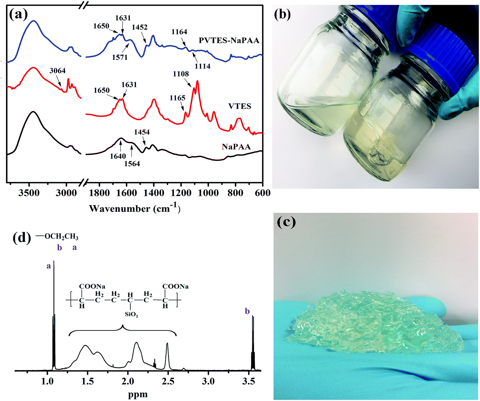 | ||
| Fig. 1 (a) The FT-IR spectra of PVTES-NaPAA, VTES and NaPAA. (b) The PVTES-NaPAA polymer dissolved in water (left), polymeric binder PVTES-NaPAA (right). (c) The robust gel after PVTES-NaPAA was dried and then immerged in water. (d) The 1H NMR spectrum of PVTES-NaPAA. | ||
The PVTES-NaPAA polymer dissolved in water (Fig. 1b) and formed a clear solution, but a robust gel formed after PVTES-NaPAA was dried and then immerged in water (Fig. 1c). Such gel formation was due to hydrolysis and then condensation of the ethyl silicate groups to form a crosslinked network for PVTES-NaPAA.
The electrochemical performance was evaluated with half coin cells. The working voltage of the cells ranged from 0.01 V to 1.2 V and the current density was 0.2C (840 mA h g−1). Fig. 2a exhibits the galvanostatic voltage profile of Si anodes in the first cycle with PVTES-NaPAA as the binder. The discharge curve shows a slope during 1.0–0.30 V, which corresponds to the formation of solid electrolyte interface (SEI) film. The discharge curve also displays a long platform during 0.30–0.01 V, which means the lithium alloying process of crystalline silicon.39 Fig. 2b shows the cyclic voltammetry (CV) of the silicon electrode for the 1st, 3rd and 5th cycle. The two peaks at 0.33 V and 0.50 V can be attributed to the low-voltage delithiation and the high-voltage delithiation of amorphous Li–Si alloys.40,41 Also, as shown in Fig. 2b, extra peaks can be observed at 0.21 V and 0.09 V after the first cycle, which indicate the crystal-to-amorphous transition.42 The weak peak at 0.09 V is invisible in the first few cycles, it can be ascribe to the overlap of strong cathodic peak in 0.01 V.29
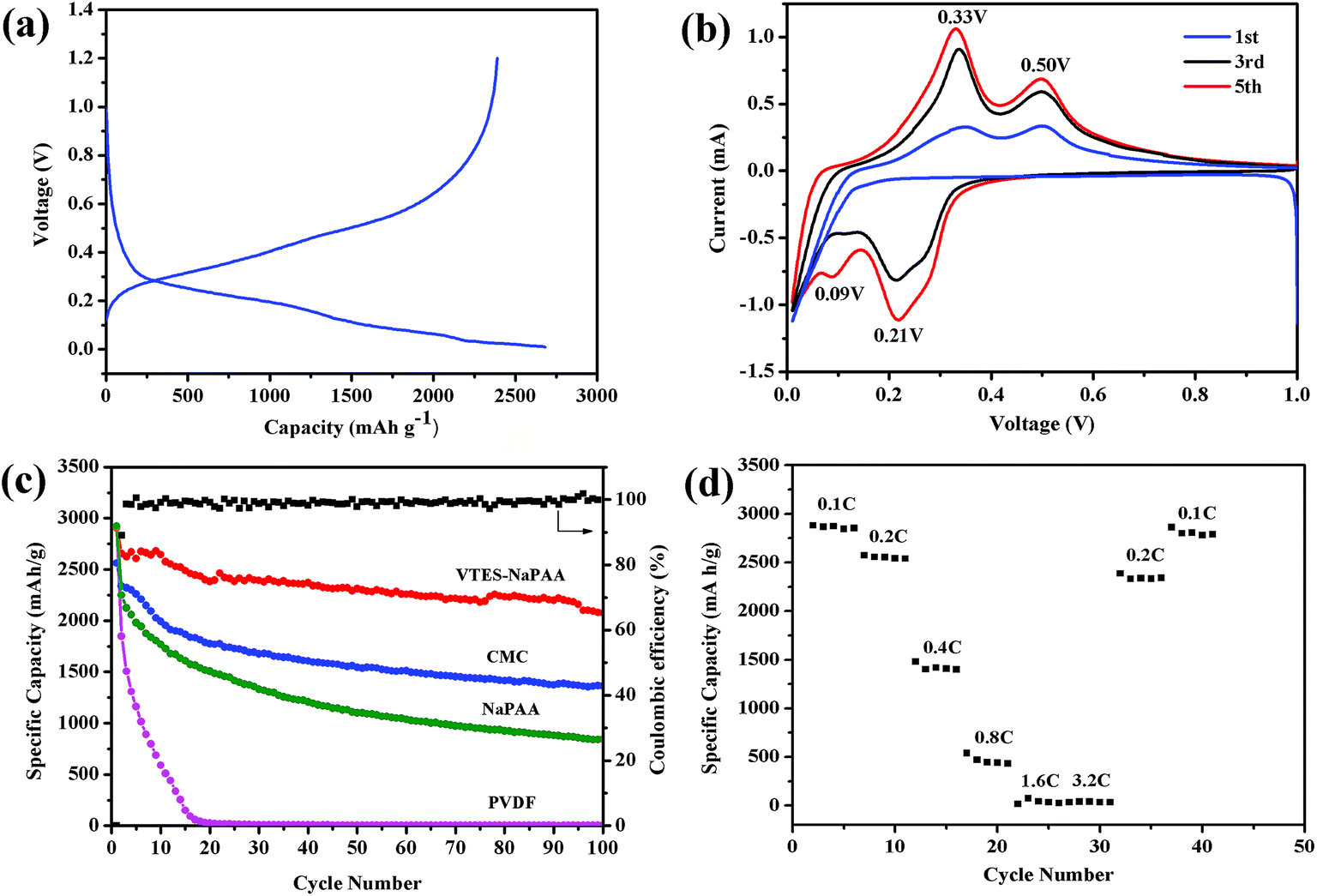 | ||
| Fig. 2 (a) The voltage profile of the Si anode with PVTES-NaPAA binder during the first charge/discharge process. (b) The cyclic voltammetry (CV) of Si anodes with PVTES-NaPAA binder for the 1st, 3rd and 5th cycle. (c) The cycling performance of Si anodes with CMC, PVDF, NaPAA and PVTES-NaPAA binders. (d) The rate performance of the SiPVTES-NaPAA with different current density from 0.1C to 3.2C. | ||
To exhibit the effect of different binders on the cycling stability, the PVTES-NaPAA was compared with common polymeric binders CMC, PVDF, NaPAA (denoted as SiPVTES-NaPAA, SiCMC, SiPVDF, SiNaPAA), as shown in Fig. 2c. The Si loading is about 0.54 mg cm−2 and the thickness of the electrode is about 15 μm, as shown in Fig. S1 (the ESI†). In the first cycle, the electrode with PVTES-NaPAA as the binder exhibited the high capacity of 2654 mA h g−1. Furthermore, the capacity after 100 cycles can still remain 2077 mA h g−1, about 78.2% capacity retention compared to the first cycle. In contrast, the electrodes with CMC and NaPAA binders only remain 57.9%, 37.5% after 100 cycles, respectively. The electrodes with PVDF binder even decayed to zero after 20 cycles. Obviously, the electrode using PVTES-NaPAA as the binder shows better cycle stability. Table S1† also compares the cycling performance with different polymers as binders for silicon-based anodes for lithium ion batteries in the literature. The cycling performance in our work is good compared to the results in the table. Moreover, the coulombic efficiency (CE) of the electrode with PVTES-NaPAA binder was 89.0% at the first cycle, and it increased to 99.9% after 100 cycles. The high coulombic efficiency might suggest a relatively stable SEI film formation on the silicon electrode surface during cycling. Furthermore, even when the loading of electrode material increased to 1.3 mg cm−2, the capacity can also retain 80% after 50 cycles and the coulombic efficiency (CE) rose from 94% at the first cycle to 99%, shown in Fig. 3. Also, the cycling performance with the mass loading of 1.92 mg cm−2 is shown in Fig. S2.† The capacity after 50 cycles can still remain about 75.1% capacity compared to the first cycle.
 | ||
| Fig. 3 The cycling performance of the Si anode with PVTES-NaPAA as the binder with the mass loading of 1.3 mg cm−2. | ||
Fig. 2d shows the rate performance of the SiPVTES-NaPAA with the current density increasing from 0.1C to 3.2C. The reversible capacity of ∼500 mA h g−1 at the current density of 0.8C can be observed in Fig. 2d. In addition, when the current density changes back to 0.2C and 0.1C, discharge capacity basically rebounds to initial value, which confirms that the SiPVTES-NaPAA has excellent reversibility.
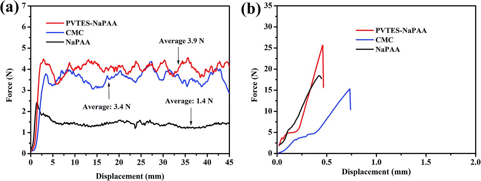
Many studies have shown that binders play the role of bonding Si nanoparticles as well as the current collector and the active material.43,44 The adhesion strength of binders is extremely important to maintain the stability of Si anodes electronic network. Herein, the 180° peel experiment was used to evaluate the adhesion strength of different binders in Si anodes, as shown in Fig. 4a. The force–displacement curves in Fig. 4a show the adhesion between the Si active material and the current collector with PVTES-NaPAA, CMC and NaPAA as binders. The average peel force of the PVTES-NaPAA is 3.9 N, which is much higher compared to CMC (3.4 N) and NaPAA (1.4 N). This higher peel force means that the PVTES-NaPAA might be more effective to make the Si electrode structure stable during cycling.43,44 The enhanced adhesion of the PVTES-NaPAA might be attributed to the multi-point contact of three-dimensional network structure, which compares to the linear structure of the CMC and NaPAA.28 Also, the adhesion test with the high loading of 0.9 mg cm−2 was carried out, as shown in Fig. S3.† From the figure, the average peel force is about 3.7 N, which changes little compared to the low loading level of 3.9 N.
 | ||
| Fig. 4 (a) The 180° peel experiment between the Si active material and the current collector with PVTES-NaPAA, CMC and NaPAA as binders. (b) The tensile tests of PVTES-NaPAA, CMC and NaPAA. | ||
Moreover, the mechanical property of binders is also a key factor for Si anodes.32 Binders which have higher Young's modulus can be more beneficial to maintain the electrode stability.43 The tensile test results in Fig. 4b displays the PVTES-NaPAA possesses the highest Young's modulus of 5.0 GPa, which is about 2 times than that of NaPAA (2.6 GPa) and CMC (2.0 GPa). This result suggests that the PVTES-NaPAA binder could effectively resist the deformation caused by volume expansion of Si anodes during cycling.43 The PVTES-NaPAA with excellent tensile strength could make the electrode be more stable during the cycling process of Si anodes.31
To deeply understand the effect of PVTES-NaPAA on the improvement of cycling performance, typical SEM images of Si electrodes with PVTES-NaPAA and NaPAA as polymeric binders were shown in Fig. 5. Fig. 5a and b show the uniformly porous structure of Si electrodes with PVTES-NaPAA and NaPAA as binders before cycling. However, obvious morphology changes were exhibited in these two samples after 100 cycles, shown in Fig. 5c and d. It can be observed that a thick SEI layer was on some areas of the electrode with NaPAA as the binder, as shown in Fig. 5d. This thick SEI film is considered to be the result of Si particles volume change and pulverization during cycling with new SEI film growing on them.45,46 In contrast, individual Si particle and porous structure was found for the electrode with PVTES-NaPAA as the binder after cycling, as shown in Fig. 5c. Thus, the uniform SEI film is believed to be formed in the PVTES-NaPAA sample. The formation of the thinner SEI film could be attributed to the PVTES-NaPAA crosslinked network which effectively accommodates the expansion of silicon materials during cycling.47
 | ||
| Fig. 5 SEM images of Si anodes with PVTES-NaPAA (a and c) and NaPAA (b and d) as binders before (a and b) and after (c and d) 100 cycles. | ||
To further demonstrate the improved cycle stability, electrochemical impedance spectroscopy (EIS) measurements of the SiPVTES-NaPAA electrode at the 10th cycle and the 100th cycle were performed in Fig. 6. As Fig. 6a shows, the Nyquist plots are composed by two approximate semicircles at high and middle frequency ranges as well as a Warburg tail at low frequency range. The general explanation of the Nyquist plots is that semicircles at high frequency range are ascribed to the SEI layer formation and the interphase electronic contact resistance between the anode material and the current collector (RSEI+int).48 The semicircle at middle frequency range is due to the resistance of the charge transfer (Rct). The Warburg tail corresponds to the Li+ diffusion resistance (Wdif).48 According to the EIS spectra, the equivalent circuit for Nyquist plot of the SiPVTES-NaPAA electrode (Fig. 6b) is provided. The equivalent circuit is constituted with four resistors, three constant phase elements in parallel and one Warburg diffusion element. It can be seen the fitting data of the 10th and 100th Nyquist plots (the solid lines in Fig. 6a) are consistent with the actual impedance data. According to the equivalent circuit, RSEI, Rint and Rct were calculated. The SEI film resistance of the SiPVTES-NaPAA electrode is about 27 Ω at the 10th cycle, and about 24 Ω at 100th cycle. Such relatively stable RSEI suggests the stable SEI film formation for the SiPVTES-NaPAA electrode during cycling, which expected a consistent result with the SEM results. The electrode also shows the decrease of the interphase electronic contact resistance from 10th cycle (21 Ω) to 100th cycle (8 Ω), suggesting the easily transformation of electrons from the Si electrode to the current collector during the cycling process.49
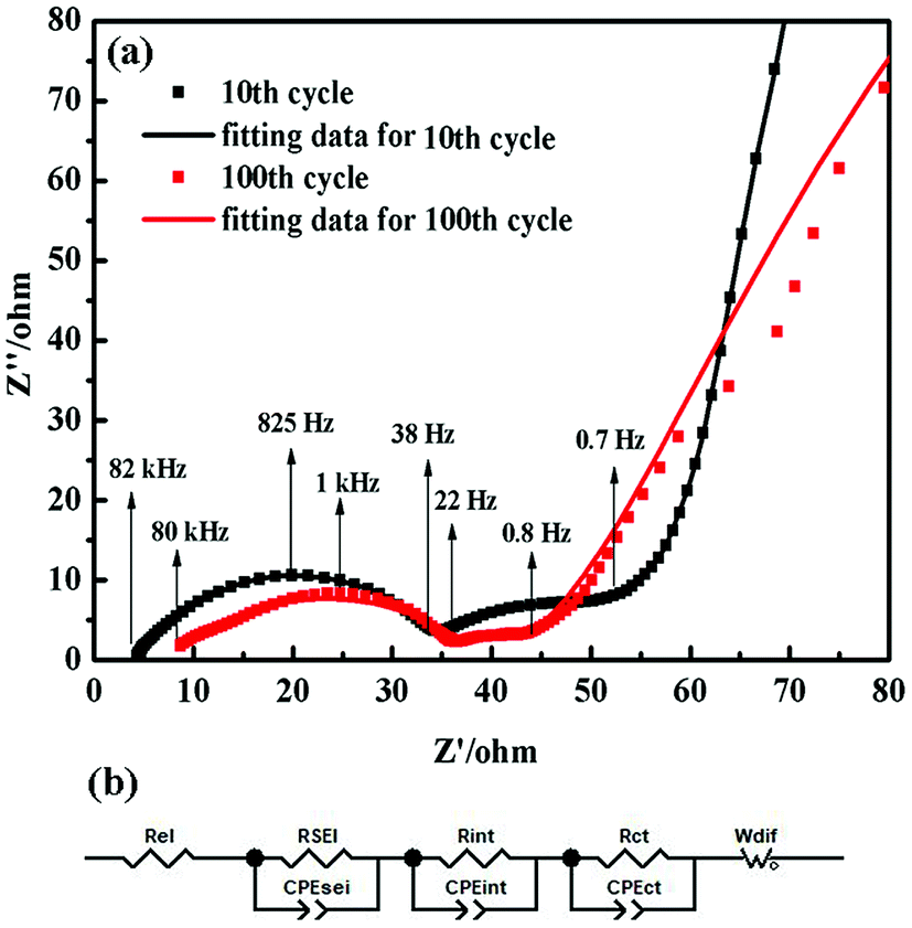 | ||
| Fig. 6 (a) The Nyquist plots of the SiPVTES-NaPAA electrode at the 10th cycle and the 100th cycle. (b) The equivalent circuit for the Nyquist plots of the SiPVTES-NaPAA electrode. | ||
The better cycle performance of SiPVTES-NaPAA could be interpreted by the special binding mechanism, which is different from CMC and PAA. The one-dimensional molecular structure of the CMC and PAA binders might only present one point contact with the Si particles. As a result, these linear structure binders could not bear the expansion and shrink of the Si particles during cycling. In comparison, the PVTES-NaPAA binder with van der Waals interaction and hydrogen bonding could form a three-dimensional crosslinked network structure around the silicon particles, thus provide multi-point contacts with Si particles (Scheme 2). This forceful 3D polymer network with multi-point contact is beneficial to improve the electrode stability during the lithiation–delithiation cycling.
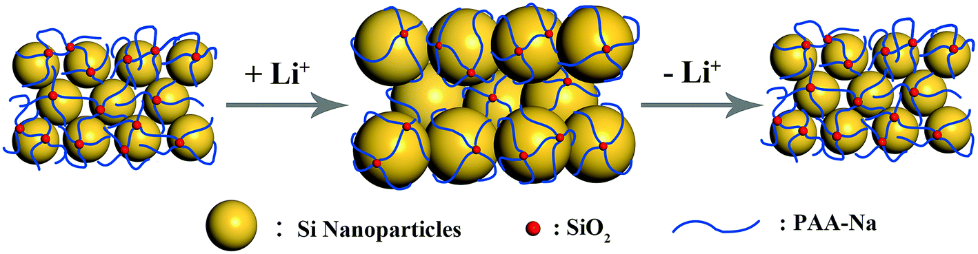 | ||
| Scheme 2 The possible working mechanism of PVTES-NaPAA binder. | ||
4. Conclusions
In summary, we have developed a polymeric binder PVTES-NaPAA for high performance Si anodes by using free radical graft co-polymerization technique. The binder can effectively form a stable SEI film on the silicon anode surface, and accommodate volume changes of Si anodes, which resulting in good cycle performance (78.2% capacity retention after 100 cycles) and high coulombic efficiency (99.9% after 100 cycles). The PVTES-NaPAA binder has a great potential for Si anodes LIBs according to its excellent cycle stability, easy to synthesis and environmentally friendly.Conflicts of interest
There are no conflicts to declare.Acknowledgements
We acknowledge the U-M/SJTU Collaborative Research Program in Nanostructured Multi-functional Li-Batteries. We also acknowledge support from National Natural Science Foundation of China (No. 51272155). Special thanks to the Instrumental Analysis Center of Shanghai Jiao Tong University.References
- J. Xu, H. R. Thomas, R. W. Francis, K. R. Lum, J. Wang and B. Liang, J. Power Sources, 2008, 177, 512–527 CrossRef.
- J. Xu, S. Dou, H. Liu and L. Dai, Nano Energy, 2013, 2, 439–442 CrossRef.
- S. Goriparti, E. Miele, F. De Angelis, E. Di Fabrizio, R. Proietti Zaccaria and C. Capiglia, J. Power Sources, 2014, 257, 421–443 CrossRef.
- C. Liu, F. Li, L. P. Ma and H. M. Cheng, Adv. Mater., 2010, 22, E28–E62 CrossRef PubMed.
- G. W. X. Tang and Y. Song, Appl. Surf. Sci., 2018, 436, 398–404 CrossRef.
- M. N. Obrovac and L. Christensen, Electrochem. Solid-State Lett., 2004, 7, A93 CrossRef.
- B. Liang, Y. Liu and Y. Xu, J. Power Sources, 2014, 267, 469–490 CrossRef.
- M. Holzapfel, H. Buqa, L. J. Hardwick, M. Hahn, A. Würsig, W. Scheifele, P. Novák, R. Kötz, C. Veit and F.-M. Petrat, Electrochim. Acta, 2006, 52, 973–978 CrossRef.
- U. Kasavajjula, C. Wang and A. J. Appleby, J. Power Sources, 2007, 163, 1003–1039 CrossRef.
- H. Wu and Y. Cui, Nano Today, 2012, 7, 414–429 CrossRef.
- J. Li and J. R. Dahn, J. Electrochem. Soc., 2007, 154, A156 CrossRef.
- Q. Tang, Z. Shan, L. Wang and X. Qin, Electrochim. Acta, 2012, 79, 148–153 CrossRef.
- H. K. Liu, Z. P. Guo, J. Z. Wang and K. Konstantinov, J. Mater. Chem., 2010, 20, 10055 RSC.
- M. K. Datta and P. N. Kumta, J. Power Sources, 2009, 194, 1043–1052 CrossRef.
- K. Hanai, Y. Liu, N. Imanishi, A. Hirano, M. Matsumura, T. Ichikawa and Y. Takeda, J. Power Sources, 2005, 146, 156–160 CrossRef.
- S. H. Yook, C. H. Park and D. W. Kim, RSC Adv., 2016, 6, 83126–83134 RSC.
- B. Koo, H. Kim, Y. Cho, K. T. Lee, N. S. Choi and J. Cho, Angew. Chem., Int. Ed. Engl., 2012, 51, 8762–8767 CrossRef PubMed.
- M. H. Ryou, J. Kim, I. Lee, S. Kim, Y. K. Jeong, S. Hong, J. H. Ryu, T. S. Kim, J. K. Park, H. Lee and J. W. Choi, Adv. Mater., 2013, 25, 1571–1576 CrossRef PubMed.
- Z. J. Han, N. Yabuuchi, S. Hashimoto, T. Sasaki and S. Komaba, ECS Electrochem. Lett., 2012, 2, A17–A20 CrossRef.
- A. Magasinski, B. Zdyrko, I. Kovalenko, B. Hertzberg, R. Burtovyy, C. F. Huebner, T. F. Fuller, I. Luzinov and G. Yushin, ACS Appl. Mater. Interfaces, 2010, 2, 3004–3010 CrossRef PubMed.
- M. Wu, X. Xiao, N. Vukmirovic, S. Xun, P. K. Das, X. Song, P. Olalde-Velasco, D. Wang, A. Z. Weber, L. W. Wang, V. S. Battaglia, W. Yang and G. Liu, J. Am. Chem. Soc., 2013, 135, 12048–12056 CrossRef PubMed.
- Y.-S. Park, E.-S. Oh and S.-M. Lee, J. Power Sources, 2014, 248, 1191–1196 CrossRef.
- H. Wu, G. Zheng, N. Liu, T. J. Carney, Y. Yang and Y. Cui, Nano Lett., 2012, 12, 904–909 CrossRef PubMed.
- L. Chen, X. Xie, J. Xie, K. Wang and J. Yang, J. Appl. Electrochem., 2006, 36, 1099–1104 CrossRef.
- J. S. Bridel, T. Azaïs, M. Morcrette, J. M. Tarascon and D. Larcher, Chem. Mater., 2010, 22, 1229–1241 CrossRef.
- S. L. Chou, Y. Pan, J. Z. Wang, H. K. Liu and S. X. Dou, Phys. Chem. Chem. Phys., 2014, 16, 20347–20359 RSC.
- J. Li, R. B. Lewis and J. R. Dahn, Electrochem. Solid-State Lett., 2007, 10, A17 CrossRef.
- L. Wei, C. Chen, Z. Hou and H. Wei, Sci. Rep., 2016, 6, 19583 CrossRef PubMed.
- L. Shen, L. Shen, Z. Wang and L. Chen, ChemSusChem, 2014, 7, 1951–1956 CrossRef PubMed.
- J. Song, M. Zhou, R. Yi, T. Xu, M. L. Gordin, D. Tang, Z. Yu, M. Regula and D. Wang, Adv. Funct. Mater., 2014, 24, 5904–5910 CrossRef.
- L. Wei and Z. Hou, J. Mater. Chem. A, 2017, 5, 22156–22162 RSC.
- Y. Park, S. Lee, S.-H. Kim, B. Y. Jang, J. S. Kim, S. M. Oh, J.-Y. Kim, N.-S. Choi, K. T. Lee and B.-S. Kim, RSC Adv., 2013, 3, 12625 RSC.
- J. Wang, C. Xu, H. Hu, L. Wan, R. Chen, H. Zheng, F. Liu, M. Zhang, X. Shang and X. Wang, J. Nanopart. Res., 2010, 13, 869–878 CrossRef.
- S.-M. Yuen, C.-C. M. Ma, C.-L. Chiang, C.-C. Teng and Y.-H. Yu, J. Polym. Sci., Part A: Polym. Chem., 2008, 46, 803–816 CrossRef.
- C. Jiao, Z. Wang, Z. Gui and Y. Hu, Eur. Polym. J., 2005, 41, 1204–1211 CrossRef.
- M. T. Jeena, T. Bok, S. H. Kim, S. Park, J. Y. Kim, S. Park and J. H. Ryu, Nanoscale, 2016, 8, 9245–9253 RSC.
- Y. Liu, W. Wang and A. Wang, Desalination, 2010, 259, 258–264 CrossRef.
- E. A. W. Anya Kuznetsova and J. T. Yates Jr, Langmuir, 1997, 13, 5322–5328 CrossRef.
- H. Wu, G. Chan, J. W. Choi, I. Ryu, Y. Yao, M. T. McDowell, S. W. Lee, A. Jackson, Y. Yang, L. Hu and Y. Cui, Nat. Nanotechnol., 2012, 7, 310–315 CrossRef PubMed.
- M. Thakur, S. L. Sinsabaugh, M. J. Isaacson, M. S. Wong and S. L. Biswal, Sci. Rep., 2012, 2, 795 CrossRef PubMed.
- X. Chen, X. Li, F. Ding, W. Xu, J. Xiao, Y. Cao, P. Meduri, J. Liu, G. L. Graff and J. G. Zhang, Nano Lett., 2012, 12, 4124–4130 CrossRef PubMed.
- C. K. Chan, R. Ruffo, S. S. Hong, R. A. Huggins and Y. Cui, J. Power Sources, 2009, 189, 34–39 CrossRef.
- S. J. C. T. Yim, Y. N. Jo, T. H. Kim, K. J. Kim, G. Jeong and Y. J. Kim, Electrochim. Acta, 2014, 136, 112–120 CrossRef.
- G. Y. Y. Xu, Y. Ma, P. Zuo and X. Cheng, J. Power Sources, 2010, 195, 2069–2073 CrossRef.
- C. K. Chan, H. Peng, G. Liu, K. McIlwrath, X. F. Zhang, R. A. Huggins and Y. Cui, Nat. Nanotechnol., 2007, 3, 31–35 CrossRef PubMed.
- J. Song, T. Xu, M. L. Gordin, P. Zhu, D. Lv, Y.-B. Jiang, Y. Chen, Y. Duan and D. Wang, Adv. Funct. Mater., 2014, 24, 1243–1250 CrossRef.
- S. H. Zhen Liu, C. Xu, Y. Luo, N. Peng, C. Qin, M. Zhou, W. Wang, L. Chen and S. Okada, RSC Adv., 2016, 6, 68371–68378 RSC.
- J. Guo, A. Sun, X. Chen, C. Wang and A. Manivannan, Electrochim. Acta, 2011, 56, 3981–3987 CrossRef.
- Y. C. S. Y. Lee, K. S. Hong, J. K. Lee, J. Y. Kim, J. S. Bae and E. D. Jeong, Appl. Surf. Sci., 2018, 447, 442–451 CrossRef.
Footnote |
| † Electronic supplementary information (ESI) available. See DOI: 10.1039/c8ra04967j |
| This journal is © The Royal Society of Chemistry 2018 |