
 Open Access Article
 This Open Access Article is licensed under a Creative Commons Attribution-Non Commercial 3.0 Unported Licence
Retracted Article: Computational fluid dynamics modeling of the millisecond methane steam reforming in microchannel reactors for hydrogen production
Junjie Chen *,
Xuhui Gao,
Longfei Yan and
Deguang Xu
*,
Xuhui Gao,
Longfei Yan and
Deguang Xu
Department of Energy and Power Engineering, School of Mechanical and Power Engineering, Henan Polytechnic University, 2000 Century Avenue, Jiaozuo, Henan 454000, P. R. China. E-mail: comcjj@163.com; Tel: +8615138057627
First published on 16th July 2018
Abstract
Methane steam reforming coupled with methane catalytic combustion in microchannel reactors for the production of hydrogen was investigated by means of computational fluid dynamics. Special emphasis is placed on developing general guidelines for the design of integrated micro-chemical systems for the rapid production of hydrogen. Important design issues, specifically heat and mass transfer, catalyst, dimension, and flow arrangement, were explored. The relative importance of different transport phenomena was quantitatively evaluated, and some strategies for intensifying the reforming process were proposed. The results highlighted the importance of process intensification in achieving the rapid production of hydrogen. High heat and mass transfer rates derived from miniaturization of the chemical system are insufficient for process intensification. Improvement of the reforming catalyst is also essential. The efficiency of heat exchange can be improved greatly if the reactor dimension is properly designed. Thermal management is required to improve the reliability of the integrated system. Co-current heat exchange improves the thermal uniformity in the system. The catalyst loading is a key factor determining reactor performance, and must be carefully designed. Finally, engineering maps were constructed to achieve the desired power output, and favorable operating conditions for the rapid production of hydrogen were identified.
1. Introduction
In recent years, there has been an increasing interest in the development of the production of synthesis gas from hydrocarbons due to its importance in many practical applications such as fuel cells and internal combustion engines.1–4 In industry, synthesis gas is produced by steam reforming of natural gas.5,6 This reaction is endothermic in nature and requires additional heat to proceed. Therefore, this process is carried out in multi-tubular fixed-bed reactors inserted into a large furnace to supply the heat required. The industrial process operates at temperatures of around 900 °C under high pressures over a Ni/α-Al2O3 catalyst with contact times exceeding one second.5,6Many efforts have been made recently to understand the catalytic partial oxidation of methane to produce synthesis gas at short contact times.7,8 In contrast, the rate of the steam reforming reaction of methane is relatively slow.5,6 Interestingly, microfabrication techniques offer new opportunities for the development of methane steam reforming at short contact times.9–12 The rapid, efficient conversion of methane to synthesis gas shows great promise for fuel cell applications.13,14 Similarly, the rapid, efficient conversion of small amounts of methane to a synthesis gas mixture would improve spark ignition engine and catalytic converter performance while lowering emissions.15,16 Therefore, further research efforts are needed in the intensification of the steam reforming process.
Valuable intermediates and products can be made under short contact-time conditions.17,18 Attempts to implement the commercial steam reforming technology in small dimensions have been made. In particular, the steam reforming of methane over highly active catalysts at short contact times is an efficient method for the production of hydrogen.9–12 Currently, a fast reforming process is a pressing and important topic of study in light of potential hydrogen utilization for fuel-cell-powered automobiles.16 Consequently, there is considerable interest in the “on-board” conversion of methane to hydrogen at short contact times. Millisecond methane steam reforming has been reported in the literature, including in microchannel or microstructured reactors,9–12,19–22 and on highly active catalysts such as rhodium.23 The reaction proceeded at millisecond contact times is feasible due to its fast kinetics and transport,10,11 and thus hydrogen production can be intensified by hundred to thousand times. Furthermore, the methane steam reforming process has been designed to operate at sub-millisecond contact times,11 even at less than 100 microseconds at the expense of low equilibrium conversion.9 Interestingly, recent literature has suggested that methane steam reforming over nickel at millisecond contact times is in principle feasible at increased catalyst loadings.24
The very high transport rates achievable in microchannel reactors allow for operating highly endothermic and exothermic processes isothermally, which is particularly important in achieving process intensification.9,19,21,25,26 Process intensification is a strategy aimed at transforming conventional chemical processes into more economical, productive and green processes, in the form of enhanced heat and mass transfer.21,22,26,27 This technology accelerates processes by enabling reactions to occur at rates up to 1000 times faster than those in conventional systems, which has the potential to reduce reaction times significantly.9–12,19,20,26,27 Furthermore, these processes can be operated under near isothermal conditions to prevent hot spots and thermal runaway.25 The net result is that microchannel process technology can significantly improve the efficiency of the production of hydrogen from methane steam reforming.25–28
Microchannel reactors have many advantages for chemical production and process development, especially the application in fuel-cell-powered automobiles, because they operate at much shorter residence times, require much simpler equipment, and can be further “scaled-out” or “numbered-up” to achieve any desired large-scale plant capacity.16 In this way, the capital and operating cost may be reduced, and a higher efficiency may be achieved.29,30 Recent studies have demonstrated that microchannel reactors exhibit high heat fluxes and high heat exchange efficiencies.31,32 These chemical processing advantages can be derived from increased heat and mass transfer in small dimensions, eventually leading to improved yield for a steam reforming process.
Much research has focused on the design strategy of millisecond reforming process. The concept of millisecond reforming process may appear to be simple, but the design strategy presents significant challenges that have not yet been fully addressed. To address this issue, great efforts have been made in recent years to illustrate how process intensification can be achieved through microchannel reactors.33–36 Reaction engineering analysis is necessary to develop new process-intensifying methods to meet the need of the rapid production of hydrogen from steam reforming. To successfully design microfabricated chemical systems and to further intensify the involved chemical process, a detailed understanding of the underlying mechanism of the transport phenomena is also necessary.
The development of design strategies for the rapid production of hydrogen in micro-devices needed for novel fuel-cell-based power sources is the motivation for this study. In order to address the challenges in realizing this vision, the primary focus of this study is on short contact time reaction systems, and specifically on methane steam reforming thermally coupled with catalytic combustion in a microchannel reactor. A microchannel reactor that enabled efficient heat exchange between exothermic and endothermic reactions in an intensified manner was modeled, as an example of short-contact-time reactor modeling. Numerical simulations with detailed transport and chemical kinetic models were conducted to understand the transport characteristics involved in the system. Some important design issues, such as heat and mass transfer, catalyst, dimension, and flow arrangement, were explored. The primary objective of this study is to develop the general guidelines for the design of integrated micro-chemical systems for the rapid production of hydrogen. Emphasis is placed on how to achieve the rapid production of hydrogen from methane steam reforming by means of process intensification.
2. Model development
Mathematical modeling plays an important role in the development of a chemical reactor.37–40 Computational fluid dynamics is a modeling technique with powerful visualization capabilities to deal with various geometry characteristics and boundary conditions. Due to the dramatic increase of computing power, computational fluid dynamics has become an efficient tool for reformer modeling,41,42 and has become an increasingly important platform for reformer design.43,44 Additionally, computational fluid dynamics modeling is necessary to provide in-depth understanding of the operating characteristics of steam reforming reactors,41–44 and to evaluate the benefits and disadvantages associated with new reformer designs.12 Various novel designs for steam reforming reactors have been developed by using computational fluid dynamics modeling.12 Computational fluid dynamics modeling serves not only as an efficient design tool,41–44 but also as a means to interpret experimental data.45,46 Furthermore, a computational fluid dynamics modeling engineering approach to new reformer designs can avoid costly, iterative experimental design processes.472.1. Description of the chemical system
The chemical system investigated is the methane steam reforming coupled with catalytic combustion occurring in a microchannel reactor. A parallel plate with supported washcoat coatings on opposite sides separates the catalytic combustion channel from the reforming channel. A schematic diagram of the reactor modeled is given in Fig. 1. The endothermic reaction and the exothermic reaction take place on opposite sides of a wall. The separating wall serves as an efficient and compact heat exchanger. Under certain operating conditions, all the combustion (or reforming) channels behave essentially alike. The use of thin washcoats can maximize the potential for very high heat fluxes.48–50 Recent studies have demonstrated that the thermal coupling between the endothermic and exothermic reactions is important in the design of small-scale chemical systems,10,11,49,50 and the integration of multiple microchannel reactors presents significant challenges in thermal management.51,52 The primary focus of this research is on exploring reactor design for optimal thermal coupling and hydrogen production.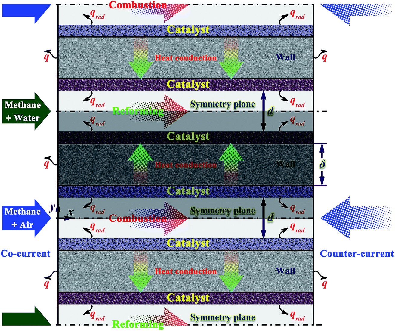 | ||
| Fig. 1 Schematic diagram of the microchannel reactor with alternating combustion and reforming channels modeled in this study. Due to the inherent symmetry of the reactor, only half of each channel, the separating plate, and the two catalyst washcoats are modeled to reduce the computational cost. The shaded region represents the computational domain of the microchannel reactor modeled in this study. | ||
There are many active metals used to promote the methane steam reforming process. In the present work, rhodium is considered due to its very high catalytic performance for the steam reforming of methane at very short contact times,53,54 but nickel is the most abundantly used metal. Furthermore, nickel-based catalysts can withstand very high temperature and exhibits good mechanical strength. Therefore, the issue that needs to be addressed is whether nickel can achieve the rapid production of hydrogen form methane steam reforming, as will be discussed in detail later.
In order to evaluate the effect of various operating conditions and design parameters, a reference point is established. The “base case” given in Table 1 is defined as a typical set of operating conditions and design parameters. The term “base case” refers to a context in which the conversion is almost complete on each side of the reactor, the formation of hot-spots or cold-spots is nearly impossible, and there is a good thermal balance between the endothermic and exothermic reactions. The molar steam-to-carbon ratio at the inlet is set as 3.0.55 If desired, the reactor width is set as 10.0 mm to obtain flow rates. A full-scale reactor design may include a much larger number of parallel plate channels, usually ranging from a few hundreds to many thousands or even more. Due to the inherent symmetry of the reactor, only half of each channel, the connecting plate, and the two catalyst washcoats are modeled to reduce the computational cost. The shaded region in Fig. 1 represents the computational domain of the reactor modeled in this paper.
| Combustion side | Reforming side | Unit | |
|---|---|---|---|
| Geometry | |||
| Channel length | 50.0 | mm | |
| Channel height | 0.2 | mm | |
![[thin space (1/6-em)]](https://www.rsc.org/images/entities/char_2009.gif) |
|||
| Solid wall | |||
| Thermal conductivity | 80.0 (300 K) | W (m K)−1 | |
| Thickness | 0.2 | mm | |
| External heat loss coefficient | 20 | W (m2 K)−1 | |
|
|||
| Gas phase | |||
| Inlet methane-air equivalence ratio | 0.8 | — | — |
| Inlet molar steam-to-carbon ratio | — | 3.0 | — |
| Inlet pressure | 0.1 | 0.1 | MPa |
| Inlet temperature | 300 | 400 | K |
| Inlet velocity | 6.0 | 2.0 | m s−1 |
|
|||
| Catalyst | |||
| Porosity | 0.5 | 0.6 | — |
| Tortuosity factor | 3 | 3 | — |
| Catalyst/geometric surface area | 20 | 20 | — |
| Mean pore diameter | 20 | 20 | nm |
| Thickness | 0.08 | 0.08 | mm |
| Density of catalyst surface sites | 2.72 × 10⁻⁹ (platinum) | 2.72 × 10⁻⁹ (rhodium) | mol cm−2 |
| 2.66 × 10⁻⁹ (nickel) | |||
On the other hand, high pressures are obviously desirable to methane reformers, and this will be the subject of future work. If the reactor is operated at high pressures, particular emphasis should be placed on the thermodynamic limit of the small scale reforming system. In addition, the thickness of the wall separating the reforming and combustion side should be several millimeters as required to maintain a high-pressure differential. Furthermore, the small scale reformer should also be designed to withstand several tens of atmospheres of pressure differential at high temperatures.
2.2. Mathematical model
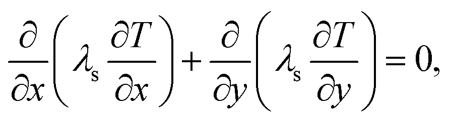
Due to the small dimension of the system, transport processes are significantly affected by diffusion. However, the length scale is still sufficiently large in comparison with the mean free path. Therefore, classical, continuum descriptions are appropriate. To reduce the complexity in the modeling of the system, it is assumed that ideal gas law is applicable and the system is in a steady state. Since the Reynolds numbers are less than 280, reactive flows in each of the channels are laminar, thus making possible to accurately simulate reaction and transport processes. The radiative heat transfer between the surfaces of the plates is modeled on each side of the reactor, as thermal radiation may be significant.52 Simple estimates indicate that for the optical path lengths and species partial pressures of interest in this study, gas-phase radiative heat transfer is negligible in comparison with convection and surface-to-surface radiative heat transfer. The commercial software ANSYS Fluent56 is adopted. Detailed reaction mechanisms and multicomponent transport are included in the model. Despite the small dimensions involved, gas-phase combustion may be significant, and thus both gas-phase and surface reaction mechanisms are included in the model. External subroutines are linked to the ANSYS Fluent software in order to model detailed gas-phase and surface reaction mechanisms. This is implemented by using CHEMKIN-CFD (developed by ANSYS Inc.; further information is also available in the literature56), which is a plug-in chemistry solver that can be linked to the ANSYS Fluent software,56 to solve the chemistry part of the solution. The equations for conservation of total mass, momentum, energy, and chemical species are solved in the gas phase.Continuity equation:
 | (1) |
Momentum equations:
 | (2) |
 | (3) |
Energy equation:
 | (4) |
Chemical species balance in the gas phase:
 | (5) |
![[small omega, Greek, dot above]](https://www.rsc.org/images/entities/i_char_e15a.gif) k, and Wk are the mass fraction, specific enthalpy, rate of appearance, and relative molecular mass of the k-th gaseous species, respectively; Vk,x and Vk,y are the streamwise and transverse components of the diffusion velocity of the k-th gaseous species, respectively.
k, and Wk are the mass fraction, specific enthalpy, rate of appearance, and relative molecular mass of the k-th gaseous species, respectively; Vk,x and Vk,y are the streamwise and transverse components of the diffusion velocity of the k-th gaseous species, respectively.
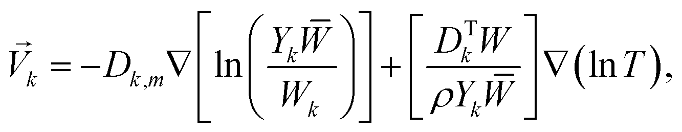
The diffusion velocity vector of the k-th gaseous species can be expressed as follows:57
 | (6) |
![[W with combining macron]](https://www.rsc.org/images/entities/i_char_0057_0304.gif) is the relative molecular mass of the mixture, DTk is the thermal diffusivity of the k-th gaseous species, and the nabla symbol ∇ denotes the differential operator del, i.e., nabla operator.
is the relative molecular mass of the mixture, DTk is the thermal diffusivity of the k-th gaseous species, and the nabla symbol ∇ denotes the differential operator del, i.e., nabla operator.
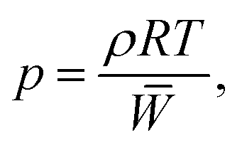
The ideal gas equation of state is
 | (7) |
 | (8) |
The equation of surface species coverage can be written as
 | (9) |
 | (10) |
The energy balance for the separating wall can be written as
 | (11) |
Each of the gas–washcoat interfaces is defined by species and energy boundary conditions. The boundary condition for the gaseous species at each of the specified gas–washcoat interfaces is given by
| (ρYkVk,y)interface + ηFcat/geoWk(ṡk)interface = 0, k = 1, …, Kg, | (12) |
 | (13) |
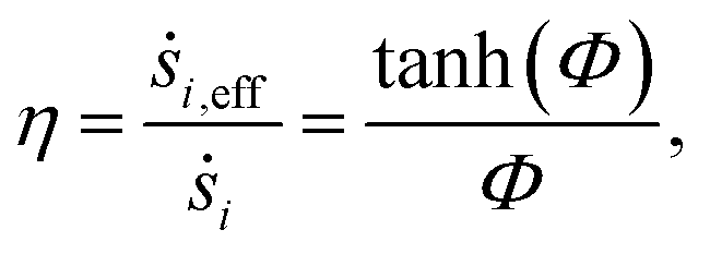
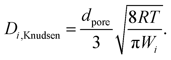
The diffusional limitations inside the catalyst washcoat is accounted for:59
 | (14) |
 | (15) |
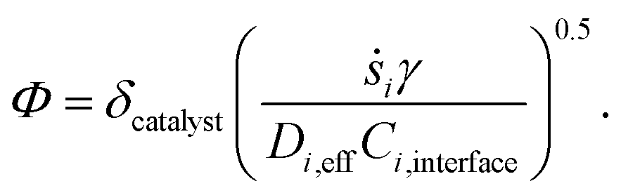
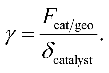
In the above equation, ṡi,eff is the effective rate of appearance of the i-th species on the surface of the catalyst, δ is the thickness of the washcoat, and Ci,interface is the concentration of the i-th species at the gas–washcoat interface. The catalytic surface area per unit volume of the washcoat, γ, is defined as
 | (16) |
The effective diffusivity of the i-th species inside the catalyst washcoat, Di,eff, is computed by adjusting for catalyst porosity and tortuosity
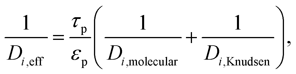 | (17) |
 | (18) |
At each of the specified gas–washcoat interfaces, heat generation by reactions must be included in the model, and thus the energy boundary condition can be written as
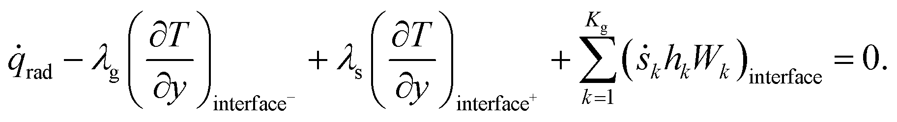 | (19) |
![[q with combining dot above]](https://www.rsc.org/images/entities/i_char_0071_0307.gif) rad is the radiative heat flux. The washcoat is considered isothermal in the transverse direction due to its small thickness. The total heat loss to the ambient is modeled as
rad is the radiative heat flux. The washcoat is considered isothermal in the transverse direction due to its small thickness. The total heat loss to the ambient is modeled as| q = ho(Tw,o − Tamb) + qrad,∞. | (20) |
| qrad,∞ = εs–∞Fs–∞σ(Tw,o4 − Tamb4). | (21) |
2.3. Chemical kinetic model
The chemical reactions used in the reactor modeling are catalytic combustion, steam reforming, water gas-shift, and reverse methanation. The catalytic combustion of methane is somewhat complicated. The possible occurrence of gas-phase combustion is discussed below. The contribution of gas-phase reactions is usually assumed to be negligible in small scale combustion systems. However, gas-phase reactions may be significant,61 especially at high temperatures;62,63 gas-phase reactions can be sustained in a confined space with a dimension as small as several sub-millimeters.61 In the present investigation, the reaction temperature is high enough so that gas-phase combustion is possible. Therefore, gas-phase reactions are not negligible on the combustion side, thus increasing the complexity in the modeling of the combustion kinetics. On the reforming side, gas-phase reactions are negligible, as will be discussed later. Note that the catalysts defined in this paper are the same as those used in the reaction mechanisms taken from the literature works described below, but the characteristics of the catalyst structure such as the tortuosity factor, porosity, and catalyst/geometric surface area are user-defined. Furthermore, only isotropic catalyst structures are considered in the present work, as described in detail in the previous section.For the combustion process, the gas-phase reaction mechanism used is the Leeds methane oxidation mechanism.64,65 The mechanism contains 105-step elementary reactions involving 25 species. All of the 25 species are included in the chemical kinetic model used. These species include all the reactants used, all the products formed, and the reaction intermediates formed, i.e., the temporary products and/or reactants in the reaction steps of the mechanism used. An order of species has been accurately defined in this mechanism, based on hydrocarbon molecules, H/C/O molecules, hydrocarbon radicals, H/C/O radicals, and buffer gases, with each class ordered in terms of increasing complexity.64,65 The surface reaction mechanism used here is that proposed by Deutschmann et al.66 The mechanism contains 24-step elementary reactions involving 11 surface species and 9 gaseous species. Further information about this mechanism can be found on the DETCHEM website.67
For the reforming process, gas-phase reactions have been found to contribute only at relatively high temperatures (in excess of 950 °C).68 Therefore, gas-phase reactions are negligible to reduce the computational complexity. The surface reactions involved in the methane steam reforming over rhodium are modeled using the mechanism proposed by Karakaya et al.69 The mechanism can be easily implemented into a chemistry solver (e.g., CHEMKIN70 and Surface-CHEMKIN71). The Karakaya's mechanism contains 48-step elementary reactions involving 12 surface species and 6 gaseous species. The surface reactions involved in the methane steam reforming over nickel are modeled using the mechanism proposed by Delgado et al.72 The Delgado's mechanism contains 52-step elementary reactions involving 14 surface species and 6 gaseous species. Further information about the Karakaya's and Delgado's mechanisms can be found on the DETCHEM website.67 On the other hand, the gas-phase reactions involved in the methane steam reforming over either rhodium or nickel are negligible, as discussed earlier.
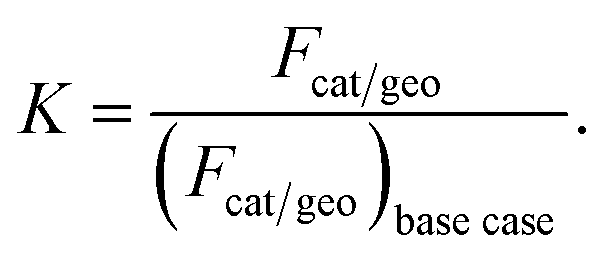
Special attention should be paid to the catalyst loading used on each side of the reactor. The catalyst loading is expressed through the area factor, Fcat/geo, as defined in eqn (13). This parameter can be used to account for the influence of catalyst loading, because there exists a linear relationship between area factor and catalyst loading.58 The area factor is also used to describe the dependence of the overall reaction rate on catalyst loading.58 The area factor is set as 20 on each side of the reactor. In this context, complete conversion is possible on each side of the reactor under the conditions given Table 1, as will be discussed in detail later.
It is worth making a brief discussion about the issue related to the definition of the catalyst loading used in the model. It is too complicated to model the actual structure of a catalyst washcoat.58 It is therefore necessary to simplify the washcoat domain of the system for the implementation of the model developed in this paper based on commercial computational fluid dynamics software, such as ANSYS Fluent. Both the area factor and the density of catalyst surface sites should be defined in order to account for the effect of the catalyst loading used. With the surface area factor, ANSYS Fluent can compute the total surface area on which the reaction takes place in each cell by multiplying this value by the volume of the cell. In this context, the evolution of chemical species and temperature in the two catalyst washcoats could be reasonably and accurately modeled with the model developed in this paper.
Thermochemical information is obtained from the provided kinetics schemes. Transport properties are obtained from the Sandia CHEMKIN transport database.57 The gas-phase and surface reaction rates are handled with the CHEMKIN70 and Surface-CHEMKIN,71 respectively.
2.4. Computation scheme
The conservation equations must to be solved with appropriate boundary conditions. Inlet temperatures, pressures, velocities, and gas compositions are specified as the feed conditions. At each of the gas–washcoat interfaces, the no-slip condition is applied. Variations in physical properties of the mixture with composition and temperature are included in the model. To compare the modeling results with an independent model, the CEA (Chemical Equilibrium with Applications) software is used to generate the equilibrium data. This software is based on minimization of Gibbs free energy.70The physical domain of the system must be transformed into a computational domain through a mesh. An orthogonal staggered mesh is used, and the node spacing is kept relatively small within the washcoat and near the entrance to the reactor. A typical mesh, totaling approximately 40000 nodes, is used for the base case given in Table 1. In addition, a mesh consisting of 80000 nodes in total is used in the case of largest dimension. For the base case, typical fluid node spacing is 250 μm in the axial direction and 2.5 μm in the transverse direction; typical wall node spacing is 250 μm in the axial direction and 5.0 μm in the transverse direction; typical washcoat node spacing is 250 μm in the axial direction and 1.0 μm in the transverse direction. A mesh independence test is performed.
Fig. 2 shows the profiles of the hydroxyl radical concentration along the longitudinal axis of the combustor for some of the meshes used for the base case. Refer to Table 1 for the operating conditions used in the numerical simulations performed here. As the mesh density increases, a trend toward convergence can be found for the solution. The coarsest mesh, totaling 2500 nodes, cannot accurately describe the concentration of the hydroxyl radical appeared in the reaction region and its peak position. Therefore, the coarsest mesh fails to accurately describe the chemical reaction occurring in the combustion channel. In contrast, the solution obtained from a mesh consisting of tens of thousands of nodes used for the base case can be considered to be reasonably accurate. A larger mesh density, up to 160000 nodes in total, offers no significant advantage.
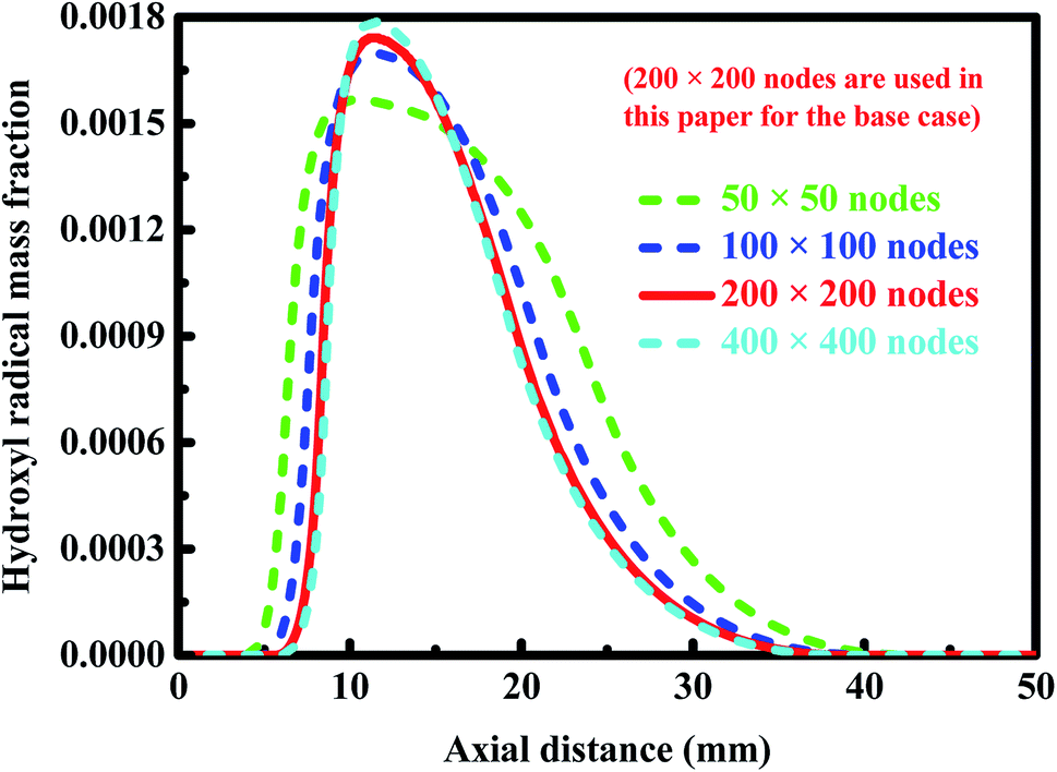 | ||
| Fig. 2 Profiles of the hydroxyl radical concentration along the longitudinal axis of the combustor for some of the meshes used for the base case. The operating conditions used in the numerical simulations conducted here are given in Table 1. | ||
The solution is deemed converged as the residuals of the conservation equations are less than 10−6. Due to the inherent stiffness of the detailed reaction mechanisms used, the convergence of the solution is often difficult. A summary of the operating conditions and design parameters used in the computational fluid dynamics simulations performed in this study is given in Table 2.
| Conditions and parameters | Combustion side | Reforming side | Unit |
|---|---|---|---|
| Reactor configuration | |||
| Channel length | 50.0 | 50.0 | mm |
| Channel height | 0.2–0.8 | 0.2–0.8 | mm |
| Wall thickness | 0.2 mm | 0.2 | mm |
| Wall thermal conductivity | 80.0 (300 K) | W (m K)−1 | |
| External heat loss coefficient | 20 | W (m2 K)−1 | |
| Flow arrangement | Co-current flow and counter-current flow | — | |
|
|||
| Catalyst washcoat | |||
| Catalyst | Pt/Al2O3 | Rh/Al2O3 and Ni/Al2O3 | |
| Ratio of catalyst loadings | 0.5–2.0 | 0.5–2.0 | — |
| Washcoat thickness | 0.08 | 0.08 | mm |
| Catalyst/geometric surface area | 20 | 20 | — |
| Washcoat mean pore diameter | 20 | 20 | nm |
| Density of catalyst surface sites | 2.72 × 10⁻⁹ (platinum) | 2.72 × 10⁻⁹ (rhodium) | mol cm−2 |
| 2.66 × 10⁻⁹ (nickel) | |||
| Washcoat porosity | 0.5 | 0.6 | — |
| Washcoat tortuosity factor | 3 | 3 | — |
|
|||
| Operating conditions | |||
| Reaction temperature (time-scale analysis) | 900, 1200, 1500 | 900, 1200, 1500 | K |
| Inlet composition | 0.8 (equivalence ratio) | 3.0 (molar steam-to-carbon ratio) | — |
| Inlet temperature | 300 | 400 | K |
| Inlet pressure | 0.1 | 0.1 | MPa |
| Inlet velocity | 0.3–6.0 | 0.2–6.0 | m s−1 |
| Wall temperature threshold | 1500 | 1500 | K |
|
|||
| Kinetic mechanisms | |||
| Gas-phase combustion | Hughes et al.64 and Turányi et al.65 | — | — |
| Catalytic combustion | Deutschmann et al.66 | — | — |
| Steam reforming | — | Karakaya et al.69 (rhodium) | — |
| Steam reforming | — | Delgado et al.72 (nickel) | — |
3. Results and discussion
3.1. Analysis of reaction and transport time scales
The methane steam reforming reaction can proceed over rhodium at millisecond contact times due to enhanced transport characteristics and the high catalytic activity of the catalyst used.10,11 Miniaturization of chemical processes results in enhanced transport rates and concomitant size reduction. On the other hand, the order of magnitude of intrinsic reaction and transport time scales are estimated to achieve intensification of the reforming process. Note that the time scale defined here refers to an order of magnitude of time.Fig. 3 shows the intrinsic reaction and transport time scales in the reforming channel and in the combustion channel. Note that a base-10 log scale is used for the vertical axis. The intrinsic reaction time scale refers to the time required for the concentration of the fuel to reduce to half its initial value
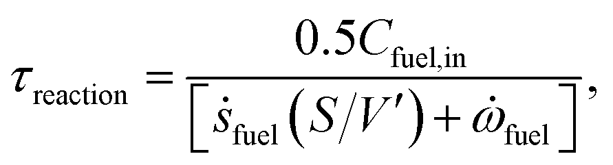 | (22) |
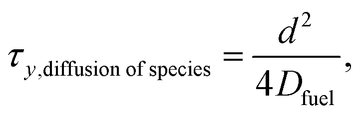 | (23) |
 | ||
| Fig. 3 Intrinsic reaction and transport time scales (Panel (a)) in the reforming channel and (Panel (b)) in the combustion channel. Note that a base-10 log scale is used for the vertical axis. | ||
Similarly, the time-scale of the heat transfer in the transverse direction can be expressed as
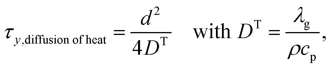 | (24) |
The mass and heat transfer in the axial direction is determined by the mean residence time
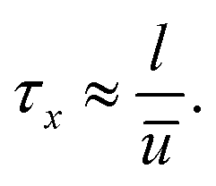 | (25) |
Fig. 3(a) shows the intrinsic reaction and transport time scales in the reforming channel. When the temperature increases, the intrinsic reforming reaction time scale decreases from about 800 to 0.2 milliseconds in the case of rhodium, and from about 700 to 3 milliseconds in the case of nickel. The difference in intrinsic reforming reaction time scale between the two catalysts is minor at low temperatures, but significant at higher temperatures. Numerical simulations are carried out under the various feed-composition conditions, the results indicate that the ratio of the intrinsic reforming reaction time scale in the case of rhodium to that in the case of nickel can be up to 20 within the temperature range examined here. At a temperature of 1200 K and 50% conversion, representative operating conditions, the rate of the reforming reaction in the case of rhodium is about one order of magnitude faster than in the case of nickel.
On the other hand, the transfer time scale in the reforming channel is on the order of tens of microseconds in the transverse direction, and on the order of a few milliseconds in the axial direction, as shown in Fig. 3(a). The intrinsic reforming reaction time scale is about one order of magnitude shorter than the residence time at temperature 1500 K in the case of rhodium, but become longer than or comparable to the residence time at temperatures 900 and 1200 K in the case of both rhodium and nickel. For the latter, possible or even considerable incomplete conversion occurs. Overall, the intensification of the reforming process is achieved in terms of transport, but the process can benefit from the improvement of the reforming catalyst.
Fig. 3(b) shows the intrinsic reaction and transport time scales in the combustion channel. As the temperature increases, the intrinsic combustion time scale decreases from about 0.005 to 0.5 milliseconds. As expected, the intrinsic combustion time scale is much shorter than the intrinsic reforming time scale, especially at low temperatures. The difference in time scale between intrinsic combustion and transverse transport is not significant at temperature 1200 K, but is up to one order of magnitude at temperatures 900 and 1500 K, as shown in Fig. 3(b). Therefore, the intensification of the combustion process is necessary in terms of transport. The improvement of the combustion catalyst is needed at low temperatures, as shown in Fig. 3(b). The residence time is much longer than all the other time scales, and thus complete conversion is always possible on the combustion side.
The rapid production of hydrogen from methane steam reforming in a microchannel reactor poses a technical challenge to the development of novel engineered catalysts.9 Novel engineered steam reforming catalysts play a strong role in increasing the productivity per unit volume. The enhanced heat and mass transfer of novel engineered catalysts may lead to improved efficiency and performance of methane steam reforming.73 To fully take the heat and mass transfer advantages of microchannel reaction technology so that rapider production of hydrogen and a greater volumetric productivity can be achieved, it is necessary to develop highly active and stable methane steam reforming catalysts. Commercial methane steam reforming catalysts are currently based on nickel supported on refractory materials doped with a variety of promoters.74 Nickel is preferable to the expensive rhodium from the perspective of cost. Significant improvements have been realized in increasing the performance of the catalysts used for methane steam reforming.74
Methane steam reforming over nickel at millisecond contact times is in principle feasible, provided that the catalyst used is properly designed with the aid of a tailored microchannel reactor design.24 Further reductions in contact time may be reasonably achieved by increasing the catalyst thickness in a manner that minimizes heat and mass transport limitations through careful design. The development of lower-cost, high-activity nickel-based catalysts is highly desirable, yet challenging.74 Methane steam reforming catalysts containing more than one active species are being investigated, and the performance of some of these novel catalyst formulations has been evaluated by Turchetti et al.75 In addition, kinetics of methane steam reforming over different catalyst-support combinations have also been studied, providing a tool for the design of steam methane reformers.75 Recently, the effect of the promoter in nickel-based catalysts has been investigated for steam methane reforming, and it has been found that the promoter plays an important role in determining the performance of these catalysts.75,76 The sintering of supports and catalysts is generally unavoidable and is a very complicated process which is accelerated at higher temperatures. On the other hand, membrane reactors show great promise for the rapid production of hydrogen from methane steam reforming.75,76 Methane steam reforming over nickel may be allowed to be carried out at millisecond contact times through intensifying the process by adopting suitable strategies, such as a high-performance catalyst and a tailored membrane reactor design.
3.2. Coupling of exothermic and endothermic reactions
The effect of thermal coupling on the reactor performance is investigated, since the management of heat is very important for reactor design.52,77 Fig. 4(a) shows the axial temperature and conversion profiles on both sides of the reactor. The wall temperature first increases and then decreases slowly along the longitudinal axis of the reactor. The outlet conversion is complete on the combustion side, whereas an outlet conversion of 98.8% is obtained on the reforming side. Fig. 4(b) shows the axial heat flux profiles on both sides of the reactor. The sub-peak appeared on the generated heat flux profile indicates the onset of gas-phase combustion, providing another route for heat generation. Catalytic combustion can provide the amount of heat required to raise the temperature of both the streams and to drive the reforming reaction. The net amount of heat generated is represented by the shaded region in Fig. 4(b). The axial position of the peak appeared on the generated heat flux profile is almost the same as that appeared on the consumed heat flux profile. The rate of the combustion reaction is much faster than that of the reforming reaction, and thus the amount of the heat released from combustion is much greater than that of the heat consumption of the reforming reaction. As a result, both of the two fluids are heated in the first half of the reactor, as illustrated in Fig. 4(a). After the middle of the reactor, there is a very small difference in temperature between the two fluids, and thus no significant heat transfer will be achieved along the remaining length of the reactor. | ||
| Fig. 4 (Panel (a)) Wall temperature and conversions in both channels, and (Panel (b)) reaction heat fluxes along the longitudinal axis of the reactor. The shaded region in Panel (b) represents the net amount of heat generated within the system. | ||
Fig. 5 shows the contour plots of the temperature and methane and hydrogen mole fractions in the reforming channel for the base case. While transverse temperature differences are negligible in the solid phase, there are steep species and temperature gradients in the gas phase near the reaction region, as shown in Fig. 5. In this context, a two-dimensional model is necessary to understand the transport characteristics involved in the system, because diffusion of both energy and species is not negligible in the axial direction. Overall, a good thermal balance is achieved between the two fluids under the conditions examined for the base case.
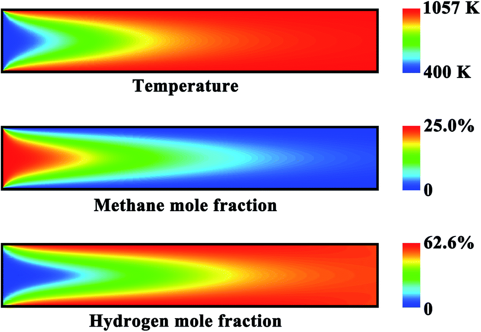 | ||
| Fig. 5 Contour plots of the temperature and methane and hydrogen mole fractions in the reforming channel for the base case. | ||
3.3. Effect of catalyst loading
Numerical simulations are performed at various catalyst loadings, by means of adjusting Fcat/geo. This parameter can be thought of as a measure of catalyst loading.58 The ratio of catalyst loadings, which is used to investigate the influence of catalyst loading, is defined as
 | (26) |
Fig. 6 shows the wall temperature profiles along the longitudinal axis of the reactor and the outlet conversions on both sides of the reactor under different catalyst-loading conditions. Fig. 6(a) and (b) show the results obtained on the combustion side. The rate of the combustion reaction decreases with decreasing the loading of the combustion catalyst. Therefore, a smaller amount of combustion catalyst results in lower wall temperatures (Fig. 6(a)) and a lower outlet conversion on each side of the reactor (Fig. 6(b)). The smallest amount of combustion catalyst (i.e., Kcombustion = 0.5) causes a cold spot to be formed within the wall at the axial position about 8 mm (the blue line in Fig. 6(a)). In contrast, the largest amount of combustion catalyst (i.e., Kcombustion = 2.0) causes a hot spot to be formed within the wall at the axial position about 12.6 mm (the red line in Fig. 6(a)). This is a situation that needs immediate attention, since hot spots may lead to rapid deactivation of the catalysts used on each side of the reactor due to high temperatures.
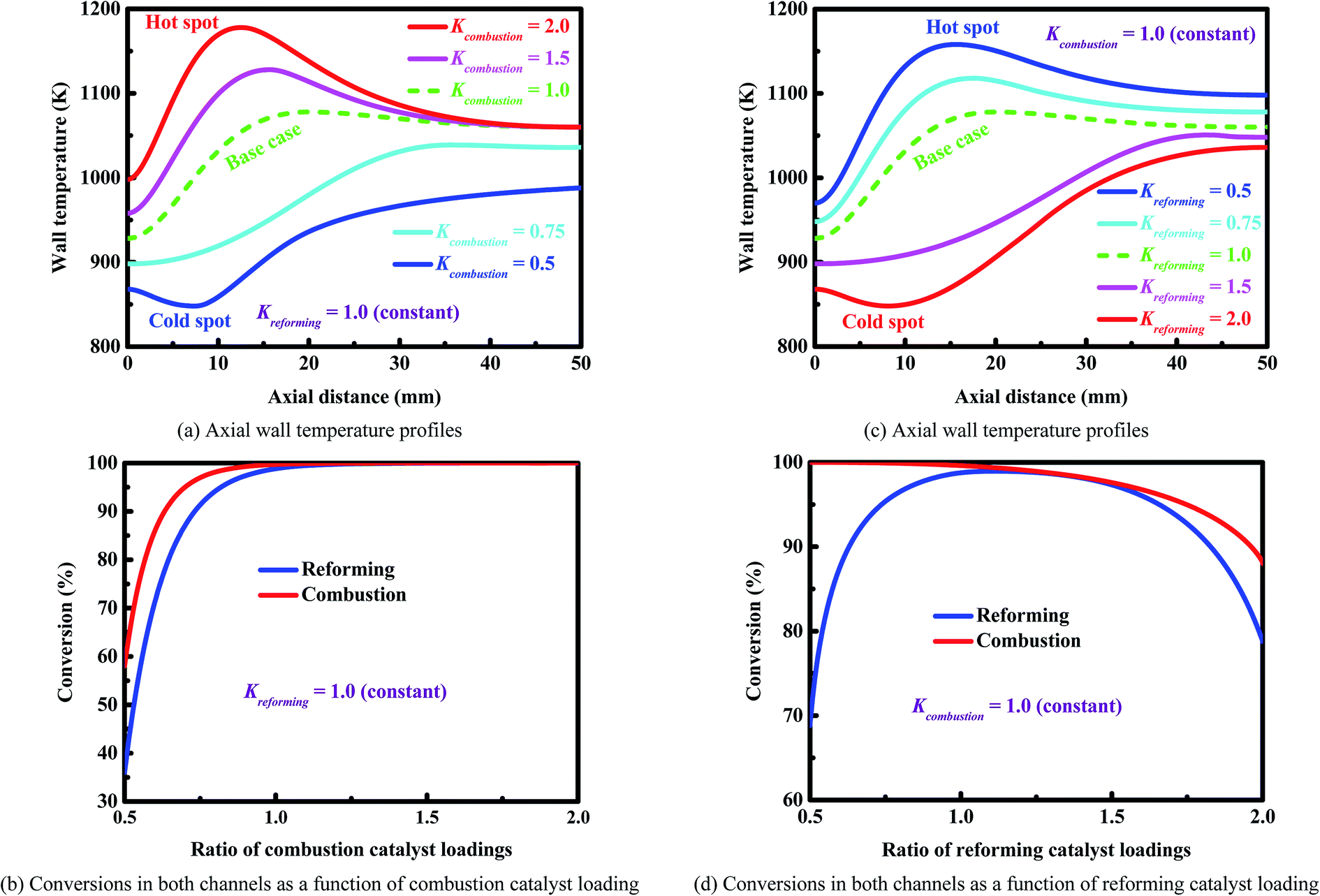 | ||
| Fig. 6 Wall temperature profiles and conversions (Panels (a) and (b)) on the combustion side and (Panels (c) and (d)) on the reforming side. | ||
Fig. 6(c) and (d) show the results obtained on the reforming side. A larger amount of reforming catalyst does not improve the performance of the reactor. The wall temperature decreases with increasing the loading of the reforming catalyst (Fig. 6(c)). In certain cases (e.g., Kreforming = 2.0), a cold spot is formed due to the cooling effect caused by a large amount of reforming catalyst (the red line in Fig. 6(c)). Overall, a larger amount of reforming catalyst results in lower wall temperatures (Fig. 6(c)) and a lower outlet conversion on each side of the reactor (Fig. 6(d)). In contrast, a smaller amount of reforming catalyst results in higher wall temperatures (Fig. 6(c)) and a higher outlet conversion on the combustion side (Fig. 6(d)), but a lower outlet conversion on the reforming side due to the lack of enough amount of reforming catalyst (Fig. 6(d)).
Fig. 7 shows the axial heat flux profiles obtained for two representative cases. In the case of Kreforming = 2.0 (Fig. 7(a)), the heat flux generated is smaller than that consumed near the entrance to the reactor, thus decreasing the wall temperature. At a certain axial position (about 8 mm), the heat flux generated becomes larger than that consumed, thus increasing the wall temperature. As a result, a cold spot is formed, as shown in Fig. 7(a) as well as Fig. 6(c) (the red line). In the case of Kreforming = 0.5 (Fig. 7(b)), the opposite occurs. The heat flux generated is much larger than that consumed near the entrance to the reactor, thus increasing the wall temperature. In the first half of the reactor, a large amount of heat released by catalytic combustion is transferred to the reforming side, and thus a peak appears on each of the two heat flux profiles. As a result, a hot spot is formed at axial position about 15.6 mm, as shown in Fig. 7(b) as well as Fig. 6(c) (the blue line). In this case, the catalyst loadings must be carefully designed to avoid deactivation of the catalyst on each side of the reactor.
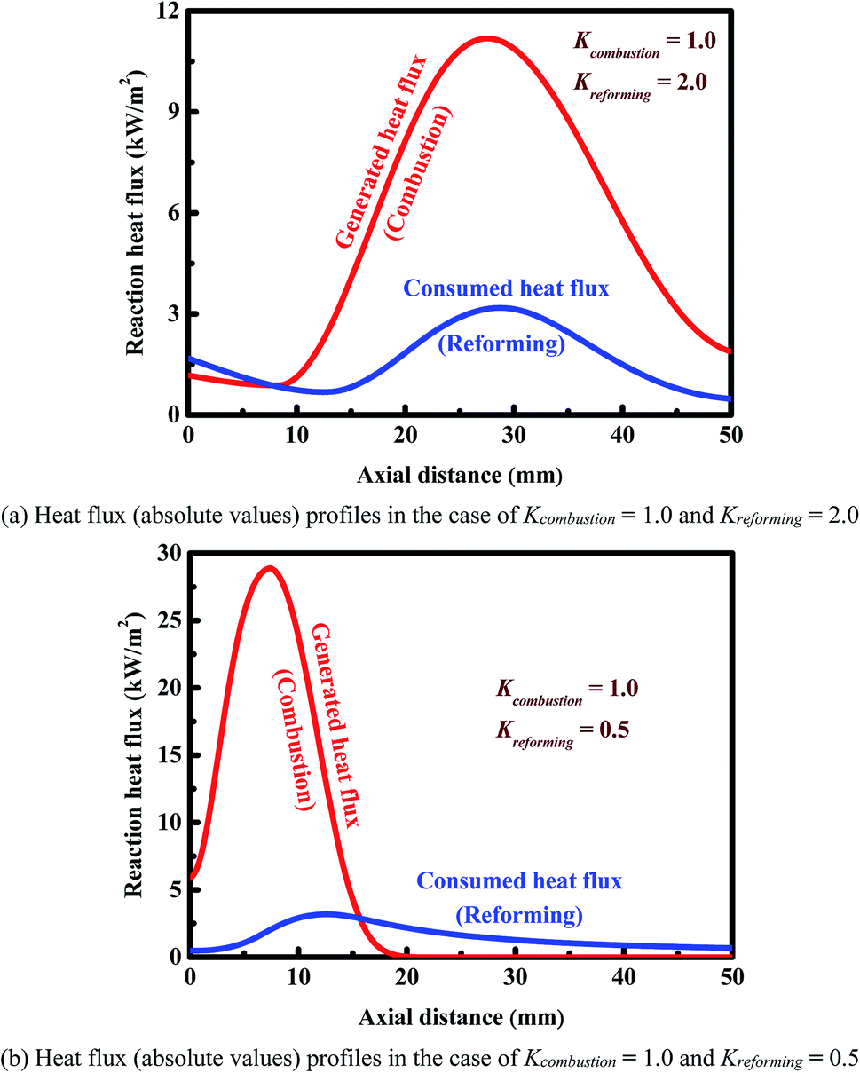 | ||
| Fig. 7 Reaction heat fluxes along the longitudinal axis of the reactor. Panel (a): a cold spot is formed in the reactor. Panel (b): a hot spot is formed in the reactor. | ||
3.4. Effect of reactor dimension
The reactor dimension should be properly designed, as large channels exacerbate diffusional resistance. Numerical simulation are performed at different channel heights to understand the role of reactor dimension. Additionally, several dimensionless numbers are used to characterize the relative strengths of the different transport phenomena. Some dimensionless numbers are shown in Fig. 8(a) for different reformer dimensions at constant inlet velocities. The transverse Damköhler number is defined as the ratio of the time scale of transverse mass transfer to intrinsic reaction
 | (27) |
 | ||
| Fig. 8 Effect of channel height on (Panel (a)) the Péclet, Fourier, and transverse Damköhler numbers as well as (Panel (b)) the maximum wall temperature and conversion. The solid and dashed lines reflect the variation of reformer dimension and combustor dimension, respectively. The inlet flow velocities of the reforming stream and the combustible stream are kept constant at 2.0 and 6.0 m s−1, respectively. In order to obtain the above dimensionless numbers, the thermodynamic properties of the mixture are computed at a point located at 10.0 mm downstream of the entrance for the sake of simplicity. | ||
The Péclet number, which characterizes the strength of convection relative to molecular diffusion, is defined as the ratio of the time scale of mass transfer in the transverse direction to residence time
 | (28) |
The Fourier number is defined as the ratio of residence time to the time scale of heat transfer in the transverse direction
 | (29) |
The three dimensionless numbers defined above give the relative strengths of the different phenomena of heat and mass transport. The thermodynamic properties of the mixture depend on the local temperature and composition, and they are computed at a point located at 10.0 mm downstream of the entrance for the sake of simplicity. This location is sufficiently downstream to allow preheating of the mixture, but not too far downstream where the reforming reaction has proceeded to completion, as illustrated in Fig. 5. The transverse Damköhler number is not sensitive to the reformer dimension, as shown in Fig. 8(a), since the reforming reaction is under kinetic control, as illustrated in Fig. 3(a). Fig. 8(a) also quantifies the relative importance of the transport time scales in the transverse direction and in the axial direction (red and blue lines). Under the conditions examined here, all of the Fourier numbers are greater than 10, whereas all of the Péclet numbers are strictly less than 0.1. Therefore, the time scales for both heat and mass transport in the transverse direction are about one order of magnitude shorter than those in the axial direction. On the other hand, the transverse transfer time scales are quite shorter than the intrinsic reforming reaction time scale (refer to Fig. 3(a) for more details). Overall, the above results, based on an analysis of the time scales, indicate that the intensification of the steam reforming process has been well implemented in terms of interphase heat and mass transfer in the reforming channel.
Fig. 8(b) shows the effect of channel height on the maximum wall temperature and conversion at constant inlet velocities. The dimension of the reactor plays an important role in determining the performance of the system in terms of both conversion and temperature. As the dimension of the reformer increases, three effects result in a decrease in the conversion on the reforming side: (a) the resistance to mass transfer increases in the transverse direction, (b) the total amount of the reforming catalyst used is relatively insufficient, and (c) there is a larger quantity of the reactants required to be heated on the reforming side. In addition, the maximum wall temperature decreases with increasing the dimension of the reformer. On the other hand, at all of the combustor dimensions examined here, complete conversion on the reforming side can always be achieved (Fig. 8(b)). The reactor performance is determined by both the energy input and the external resistance to mass transfer. As dimension of the combustor increases, the conversion on the combustion side decreases due primarily to the enhanced external resistance to mass transfer. In contrast, the temperature increases first and decreases later (Fig. 8(b)). In the case of smaller combustors, conversion is almost complete on each side of the reactor; in addition, the temperature increases with increasing the dimension of the combustor due primarily to the increased quantity of the reactants. In the case of larger combustors, the conversion is incomplete on the combustion side, and the temperature decreases with increasing the dimension of the combustor due primarily to the enhanced external resistance to mass transfer.
Overall, the reactor dimension can significantly affect the performance of the system in terms of both conversion and temperature for a given inlet velocity. The reactor dimension needs to be properly designed to improve the efficiency of heat exchange.
3.5. Effect of flow arrangement
The arrangement of the endothermic and exothermic flows can greatly affect the internal heat exchange and thus the reactor performance.78 Counter-current heat exchange systems, where the hot fluid and the cold fluid flow in opposite directions to each other, offer many advantages over co-current (i.e., parallel) heat exchange systems, where the two fluids flow in the same direction.79 However, an efficient operation requires not only a good thermal coupling, but also high reliability. The effect of flow arrangement on the reactor performance is investigated. Comparisons are made in terms of reactor performance between the two heat exchange systems. Since a high production rate of hydrogen is highly desirable in practice,10–12 high reforming stream flow rates are considered here.Both arrangements of the endothermic and exothermic flows in the alternate channels have been illustrated in Fig. 1. A comparison is made based on the axial heat flux and conversion profiles (Fig. 9(a) and (b)). Fig. 9(a) shows the axial heat flux profiles obtained for both heat exchange systems. The axial heat flux profiles are more uniform for the co-current heat exchange system, but more concentrated towards the reformer outlet for the counter-current heat exchange system. The ratio of the amount of heat generated to heat consumed is 0.6 at the reformer entrance for the counter-current heat exchange system and 1.6 for the co-current heat exchange system. Accordingly, the cooling effect, as described early, becomes more pronounced and a cold spot is formed for the counter-current heat exchange system. The ratio of the amount of heat generated to heat consumed is 4.8 at the reformer outlet for the counter-current heat exchange system and 2.8 for the co-current heat exchange system, eventually leading to localized overheating for each of the two systems.
 | ||
| Fig. 9 (Panel (a)) Reaction heat fluxes and (Panel (b)) conversions along the longitudinal axis of the reactor. The solid and dashed lines refer to the co-current heat exchange system and the counter-current heat exchange system, respectively. The reactor is better balanced thermally by implementing co-current heat exchange. | ||
Fig. 9(b) shows the axial conversion profiles for the two flow arrangements. The counter-current heat exchange system has a higher conversion at the combustor outlet than the co-current heat exchange system. For the counter-current heat exchange system, most of the heat generated by catalytic combustion is released near the combustor entrance (i.e., near the reformer outlet; refer to Fig. 1 for more details), and subsequently transferred to the reforming side. Therefore, special attention should be given to the thermal imbalance within the counter-current heat exchange system, and thermal management is always necessary to improve the reliability of the system. Furthermore, the thermal imbalance greatly increases the occurrence probability of gas-phase combustion, the counter-current heat exchange system must be carefully designed to avoid thermal runaway failures. On the other hand, the counter-current heat exchange system has a higher conversion at the reformer outlet than the co-current heat exchange system.
Comparisons are made between the two heat exchange systems in terms of multiple performance criteria, and the results are summarized in Table 3. A good thermal balance is achieved within the co-current heat exchange system, which can result in hot spot elimination and thus is a potential advantage. Better utilization of the overall heat generated by catalytic combustion is possible for the counter-current heat exchange system, making it possible to improve the conversion on each side of the reactor. The counter-current heat exchange system will cause a larger temperature gradient over the length of the reactor, and in the transverse direction. Therefore, thermal management is always necessary to avoid thermal runaway failures and reactor extinguishing. For the counter-current heat exchange system, localized insufficient heat exchange may cause hot spots or cold spots to form. The occurrence of hot spots imposes more severe constraints on the wall materials and catalysts used in the manufacture of microchannel reactors; cold spots may cause reactor extinguishing.
| Co-current | Counter-current | |
|---|---|---|
| Inlet flow velocity of the reforming stream | 3.0 m s−1 | |
| Inlet flow velocity of the combustible stream | 6.0 m s−1 | |
| Outlet conversion on the reforming side | 48.6 | 58.7 |
| Outlet conversion on the combustion side | 75.6 | 79.0 |
| Maximum wall temperature | 1047 K | 1160 K |
| Minimum wall temperature | 870 K | 848 K |
| Transverse temperature difference in the gas phase | ||
| Maximum | 570 K | 687 K |
| Minimum | −66 K | −180 K |
| Ratio between overall generated and consumed heat fluxes | 3.78 | 3.26 |
| Ratio between local generated and consumed heat fluxes | ||
| At the reformer outlet | 2.8 | 4.8 |
| At the reformer entrance | 1.6 | 0.6 |
3.6. Engineering maps and operating windows
The microchannel reactor should be properly designed to meet the requirements of the rapid production of hydrogen. In light of this, engineering maps are presented here, and operating windows are also identified. Fig. 10(a) gives an operation diagram representing the power output at different residence times of the combustible stream, assuming full utilization of the hydrogen produced from methane steam reforming. The shaded region in Fig. 10(a) depicts the operation window delimited by two types of the limits indicated. Fig. 10(a) shows that a balance between the two flow rates is required to ensure reliable operation of the device. The reactor can be operated effectively within a specified power range which varies based on the flow rate of combustible stream, ranging from the minimum power output to the maximum power output, as described below.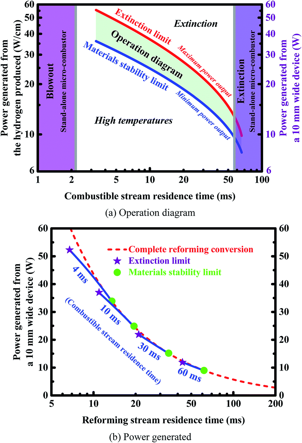 | ||
| Fig. 10 Panel (a) shows an operation diagram representing the power output at different residence times of the combustible stream, assuming full utilization of the hydrogen produced from methane steam reforming. The gray vertical lines represent the lower and upper bounds determined by the critical flow velocities in a stand-alone micro-combustor. Panel (b) shows the power generated at different residence times of the reforming stream, assuming full utilization of the hydrogen produced from methane steam reforming in a reactor with a width of 10.0 mm. The “circle” and “pentagram” symbols indicate the stability limits of combustion and materials, respectively. | ||
The minimum power output is determined by the stability limits of the materials and catalysts used.10–12 Since the reactor generates heat during operation, thermal management is required to ensure that the device is operating below the maximum operating temperature allowed. The heat generated by the catalytic combustion leads to a significant increase in catalyst temperature. Therefore, the stability of catalysts at high temperatures is of considerable interest. It is possible to design reactors in which efficient heat transfer is used to minimize temperature rise but particular attention must be paid in all cases to the temperature stability of the catalysts and materials used. In the context of high heat fluxes, the wall temperatures of an integrated system should not exceed a certain threshold in order to avoid deactivation of the catalyst on each side of the reactor. The threshold temperature (i.e., peak operating temperature or maximum normal operating temperature) of the reactor is set as 1500 K,10–12 beyond which the device may no longer function.
On the other hand, the maximum power output is determined by the maximum amount of hydrogen that can be produced before extinction occurs when the flow rate of reforming stream is sufficiently high. Outside this range of power output, the reactor will no longer function when the flow rate of combustible stream is kept constant. However, higher power output can be achieved by connecting multiple reactor units in parallel.
The reactor can also be operated effectively within a specified range of combustible stream residence-time, which is determined by the stability limits of combustion, i.e., both extinction and blowout.80 Extinction occurs due to a lack of heat generated, whereas blowout occurs due to a lack of residence time. The critical flow velocities in a stand-alone micro-combustion system are determined on the basis of a methane–air mixture in which the inlet composition is given in Table 1 (i.e., inlet equivalence ratio 0.8). The resulting prohibited window where combustion cannot be self-sustained is illustrated in Fig. 10(a) as the vertical shaded regions to ensure that the residence time of the combustible stream lies within well-defined lower and upper bounds determined by the critical flow velocities in a stand-alone micro-combustor.
The power output as a function of the flow rate of the reforming stream is investigated at various residence-times of the combustible stream by using a two-parameter continuation. Fig. 10(b) shows the power generated at different residence times of the reforming stream, assuming full utilization of the hydrogen produced from methane steam reforming in a reactor with a width of 10.0 mm. The “circle” and “pentagram” symbols indicate the stability limits of combustion and materials, respectively. Appropriate adjustments should be made to the flow rates on both sides of the reactor in order to ensure high outlet conversions, as shown in Fig. 10(b). The flow rates need to be carefully designed to meet the requirements of the stability of both combustion and materials.
The engineering maps presented in Fig. 10 can serve as a design tool for improving and optimizing the performance of an integrated micro-chemical system. Based on the operation regime presented in Fig. 10(a), an estimation about the range of the residence time of the combustible stream can be made for desired power output. Based on the power output plotted in Fig. 10(b), an estimation about the range of the residence time of the reforming stream can finally be made. Unfortunately, the range of each of the residence times is rather narrow, and thus the flow rates need to be carefully designed, as discussed above. The middle range of the residence time allowed for the combustible stream (Fig. 10(a)) and the lower bound of the residence time allowed for the reforming stream (Fig. 10(b)) will ensure higher fuel utilization and nearly complete conversion on the reforming side. This holds great promise for applications in fuel cells.
4. Conclusions
Methane steam reforming coupled with catalytic combustion in microchannel reactors was investigated, with the aim of achieving the rapid production of hydrogen. In order to optimize the performance of the small scale system, the effect of four typical variables of interest was investigated. The main points can be summarized as follows:• The rapid production of hydrogen from methane steam reforming is feasible, provided that the reforming catalyst, flow rate, and reactor dimension are properly designed.
• Miniaturization of the chemical system is insufficient for process intensification. An efficient reforming catalyst is also necessary. Overall, miniaturization of the chemical system and the improvement of the reforming catalyst must be symbiotic.
• The reactor dimension needs to be properly designed to achieve high transport rates for the intensification of the steam reforming process.
• The catalyst loading is a key factor determining reactor performance, and must be carefully designed to avoid hot spots within the wall or low conversions on both sides of the reactor.
• Counter-current operation is not desirable due to the greater extremes of temperature, despite the fact that slightly better performance can be achieved. In contrast, co-current operation is recommended, as the reactor is better balanced thermally.
• A balance between the flow rates on both sides of the reactor is required to ensure reliable operation of the system. The flow rates need to be carefully designed to meet the requirements of the stability of both materials and combustion.
• From a practical point of view, the costs of the noble metal catalysts used here might be tolerable for microfabricated chemical systems. However, it is highly desirable to develop high-activity catalysts with lower cost.
The results may prove useful to those involved in the design, optimization and modification of the methane steam reforming process for the small-scale production of hydrogen and other related processes. While microchannel reactors offer many advantages for chemical production and process development, further research efforts are required to realize this microreaction technology. Special attention should be paid to the problem of catalyst deactivation. In addition, thermal management is always necessary to improve the reliability of these microfabricated chemical systems. This potential solution is currently being investigated. Furthermore, novel design methodologies are clearly needed to realize excellent thermal uniformity, high transport rates, and low pressure drop, and thus further work in design optimization is needed.
Conflicts of interest
There are no conflicts to declare.Acknowledgements
This work was supported by the National Natural Science Foundation of China (No. 51506048) and the Fundamental Research Funds for the Universities of Henan Province (No. NSFRF140119).References
- M. Mundhwa and C. P. Thurgood, Methane steam reforming at low steam to carbon ratios over alumina and yttria-stabilized-zirconia supported nickel-spinel catalyst: experimental study and optimization of microkinetic model, Fuel Process. Technol., 2017, 168, 27–39 CrossRef.
- P. Schwach, X. Pan and X. Bao, Direct conversion of methane to value-added chemicals over heterogeneous catalysts: challenges and prospects, Chem. Rev., 2017, 117(13), 8497–8520 CrossRef PubMed.
- L. Tartakovsky and M. Sheintuch, Fuel reforming in internal combustion engines, Prog. Energy Combust. Sci., 2018, 67, 88–114 CrossRef.
- E. L. V. Eriksson and E. M. Gray, Optimization and integration of hybrid renewable energy hydrogen fuel cell energy systems – a critical review, Appl. Energy, 2017, 202, 348–364 CrossRef.
- B. M. Cruz and J. D. da Silva, A two-dimensional mathematical model for the catalytic steam reforming of methane in both conventional fixed-bed and fixed-bed membrane reactors for the production of hydrogen, Int. J. Hydrogen Energy, 2017, 42(37), 23670–23690 CrossRef.
- B. F. Oechsler, J. C. S. Dutra, R. C. P. Bittencourt and J. C. Pinto, Simulation and control of steam reforming of natural gas-reactor temperature control using residual gas, Ind. Eng. Chem. Res., 2017, 56(10), 2690–2710 CrossRef.
- R. Yuan, Z. He, Y. Zhang, W. Wang, C. Chen, H. Wu and Z. Zhan, Partial oxidation of methane to syngas in a packed bed catalyst membrane reactor, AIChE J., 2016, 62(6), 2170–2176 CrossRef.
- H. E. Figen and S. Z. Baykara, Effect of ruthenium addition on molybdenum catalysts for syngas production via catalytic partial oxidation of methane in a monolithic reactor, Int. J. Hydrogen Energy, 2018, 43(2), 1129–1138 CrossRef.
- A. L. Y. Tonkovich, B. Yang, S. T. Perry, S. P. Fitzgerald and Y. Wang, From seconds to milliseconds to microseconds through tailored microchannel reactor design of a steam methane reformer, Catal. Today, 2007, 120(1), 21–29 CrossRef.
- G. D. Stefanidis, N. S. Kaisare, M. Maestri and D. G. Vlachos, Methane steam reforming at microscales: operation strategies for variable power output at millisecond contact times, AIChE J., 2009, 55(1), 180–191 CrossRef.
- G. D. Stefanidis and D. G. Vlachos, Millisecond methane steam reforming via process and catalyst intensification, Chemical Engineering & Technology, 2008, 31(8), 1201–1209 Search PubMed.
- J. D. Holladay and Y. Wang, A review of recent advances in numerical simulations of microscale fuel processor for hydrogen production, J. Power Sources, 2015, 282, 602–621 CrossRef.
- S. S. Kostenko, A. N. Ivanova, A. A. Karnaukh and E. V. Polianczyk, Conversion of methane to synthesis gas in a non-premixed reversed-flow porous bed reactor: a kinetic modeling, Chemical Engineering and Processing: Process Intensification, 2017, 122, 473–486 CrossRef.
- D. Pashchenko, Effect of the geometric dimensionality of computational domain on the results of CFD-modeling of steam methane reforming, Int. J. Hydrogen Energy, 2018, 43(18), 8662–8673 CrossRef.
- W. C. Nadaleti and G. Przybyla, Emissions and performance of a spark-ignition gas engine generator operating with hydrogen-rich syngas, methane and biogas blends for application in southern Brazilian rice industries, Energy, 2018, 154, 38–51 CrossRef.
- G. Diglio, D. P. Hanak, P. Bareschino, F. Pepe, F. Montagnaro and V. Manovic, Modelling of sorption-enhanced steam methane reforming in a fixed bed reactor network integrated with fuel cell, Appl. Energy, 2018, 210, 1–15 CrossRef.
- K. Urasaki, S. Kado, A. Kiryu, K. Imagawa, K. Tomishige, R. Horn, O. Korup and Y. Suehiro, Synthesis gas production by catalytic partial oxidation of natural gas using ceramic foam catalyst, Catal. Today, 2018, 299, 219–228 CrossRef.
- A. Moral, I. Reyero, C. Alfaro, F. Bimbela and L. M. Gandía, Syngas production by means of biogas catalytic partial oxidation and dry reforming using Rh-based catalysts, Catal. Today, 2018, 299, 280–288 CrossRef.
- C. Cao, N. Zhang, D. Dang and Y. Cheng, Numerical evaluation of a microchannel methane reformer used for miniaturized GTL: operating characteristics and greenhouse gases emission, Fuel Process. Technol., 2017, 167, 78–91 CrossRef.
- C. Cao, N. Zhang, D. Dang and Y. Cheng, Hybrid modeling of integrated microchannel methane reformer for miniaturized GTL application using an effectiveness factor submodel based on complex surface chemistry, Chem. Eng. J., 2017, 316, 715–726 CrossRef.
- M. Sattari-Najafabadi, M. N. Esfahany, Z. Wu and B. Sunden, Mass transfer between phases in microchannels: A review, Chem. Eng. Process., 2018, 127, 213–237 CrossRef.
- R. J. Kee, C. Karakaya and H. Zhu, Process intensification in the catalytic conversion of natural gas to fuels and chemicals, Proc. Combust. Inst., 2017, 36(1), 51–76 CrossRef.
- Z. Boukha, M. Gil-Calvo, B. de Rivas, J. R. González-Velasco, J. I. Gutiérrez-Ortiz and R. López-Fonseca, Behaviour of Rh supported on hydroxyapatite catalysts in partial oxidation and steam reforming of methane: on the role of the speciation of the Rh particles, Appl. Catal., A, 2018, 556, 191–203 CrossRef.
- C. Cao, N. Zhang, X. Chen and Y. Cheng, A comparative study of Rh and Ni coated microchannel reactor for steam methane reforming using CFD with detailed chemistry, Chem. Eng. Sci., 2015, 137, 276–286 CrossRef.
- A. Tanimu, S. Jaenicke and K. Alhooshani, Heterogeneous catalysis in continuous flow microreactors: A review of methods and applications, Chem. Eng. J., 2017, 327, 792–821 CrossRef.
- B. A. Wilhite, Unconventional microreactor designs for process intensification in the distributed reforming of hydrocarbons: a review of recent developments at Texas A&M University, Curr. Opin. Chem. Eng., 2017, 17, 100–107 CrossRef.
- X. Yao, Y. Zhang, L. Du, J. Liu and J. Yao, Review of the applications of microreactors, Renewable Sustainable Energy Rev., 2015, 47, 519–539 CrossRef.
- B. Blakeley and N. Sullivan, Fuel processing in a ceramic microchannel reactor: expanding operating windows, Int. J. Hydrogen Energy, 2016, 41(6), 3794–3802 CrossRef.
- N. Engelbrecht, S. Chiuta and D. G. Bessarabov, A highly efficient autothermal microchannel reactor for ammonia decomposition: analysis of hydrogen production in transient and steady-state regimes, J. Power Sources, 2018, 386, 47–55 CrossRef.
- N. Zhang, X. Chen, B. Chu, C. Cao, Y. Jin and Y. Cheng, Catalytic performance of Ni catalyst for steam methane reforming in a micro-channel reactor at high pressure, Chemical Engineering and Processing: Process Intensification, 2017, 118, 19–25 CrossRef.
- M. Mundhwa, C. P. Thurgood, H. Dhingra, R. D. Parmar and B. A. Peppley, A comparative computational study of diesel steam reforming in a catalytic plate heat – exchange reactor, AIChE J., 2017, 63(3), 1102–1113 CrossRef.
- M. Mundhwa and C. P. Thurgood, Improved performance of a catalytic plate reactor coated with distributed layers of reforming and combustion catalysts for hydrogen production, React. Chem. Eng., 2018 10.1039/C8RE00013A , in press.
- P. Inbamrung, T. Sornchamni, C. Prapainainar, S. Tungkamani, P. Narataruksa and G. N. Jovanovic, Modeling of a square channel monolith reactor for methane steam reforming, Energy, 2018, 152, 383–400 CrossRef.
- G. Ji, M. Zhao and G. Wang, Computational fluid dynamic simulation of a sorption-enhanced palladium membrane reactor for enhancing hydrogen production from methane steam reforming, Energy, 2018, 147, 884–895 CrossRef.
- V. Palma, A. Ricca, M. Martino and E. Meloni, Innovative structured catalytic systems for methane steam reforming intensification, Chemical Engineering and Processing: Process Intensification, 2017, 120, 207–215 CrossRef.
- C.-H. Kim, J.-Y. Han, H. Lim, K.-Y. Lee and S.-K. Ryi, Methane steam reforming using a membrane reactor equipped with a Pd-based composite membrane for effective hydrogen production, Int. J. Hydrogen Energy, 2018, 43(11), 5863–5872 CrossRef.
- A. Settar, R. Nebbali, B. Madani and S. Abboudi, Numerical study on the effects of the macropatterned active surfaces on the wall-coated steam methane reformer performances, Int. J. Hydrogen Energy, 2017, 42(2), 1490–1498 CrossRef.
- P. Ribeirinha, M. Abdollahzadeh, A. Pereira, F. Relvas, M. Boaventura and A. Mendes, High temperature PEM fuel cell integrated with a cellular membrane methanol steam reformer: experimental and modelling, Appl. Energy, 2018, 215, 659–669 CrossRef.
- M.-H. Jin, C.-B. Lee, D.-W. Lee, S.-W. Lee, J.-W. Park, D. Oh, K.-R. Hwang, K.-Y. Lee and J.-S. Park, Microchannel methane steam reformers with improved heat transfer efficiency and their long-term stability, Fuel, 2016, 176, 86–92 CrossRef.
- S. Bac, S. Keskin and A. K. Avci, Modeling and simulation of water-gas shift in a heat exchange integrated microchannel converter, Int. J. Hydrogen Energy, 2018, 43(2), 1094–1104 CrossRef.
- L. Lao, A. Aguirre, A. Tran, Z. Wu, H. Durand and P. D. Christofides, CFD modeling and control of a steam methane reforming reactor, Chem. Eng. Sci., 2016, 148, 78–92 CrossRef.
- A. Tran, A. Aguirre, H. Durand, M. Crose and P. D. Christofides, CFD modeling of a industrial-scale steam methane reforming furnace, Chem. Eng. Sci., 2017, 171, 576–598 CrossRef.
- A. Tran, M. Pont, A. Aguirre, H. Durand, M. Crose and P. D. Christofides, Bayesian model averaging for estimating the spatial temperature distribution in a steam methane reforming furnace, Chem. Eng. Res. Des., 2018, 131, 465–487 CrossRef.
- Z. Wu, A. Aguirre, A. Tran, H. Durand, D. Ni and P. D. Christofides, Model predictive control of a steam methane reforming reactor described by a computational fluid dynamics model, Ind. Eng. Chem. Res., 2017, 56(20), 6002–6011 CrossRef.
- M. Behnam, A. G. Dixon, P. M. Wright, M. Nijemeisland and E. H. Stitt, Comparison of CFD simulations to experiment under methane steam reforming reacting conditions, Chem. Eng. J., 2012, 207–208, 690–700 CrossRef.
- P. Ribeirinha, M. Boaventura, J. C. B. Lopes, J. M. Sousa and A. Mendes, Study of different designs of methanol steam reformers: Experiment and modeling, Int. J. Hydrogen Energy, 2014, 39(35), 19970–19981 CrossRef.
- A. Tran, A. Aguirre, M. Crose, H. Durand and P. D. Christofides, Temperature balancing in steam methane reforming furnace via an integrated CFD/data-based optimization approach, Comput. Chem. Eng., 2017, 104, 185–200 CrossRef.
- Y. M. Bruschi, E. López, M. N. Pedernera and D. O. Borio, Coupling exothermic and endothermic reactions in an ethanol microreformer for H2 production, Chem. Eng. J., 2016, 294, 97–104 CrossRef.
- M. Mundhwa and C. P. Thurgood, Numerical study of methane steam reforming and methane combustion over the segmented and continuously coated layers of catalysts in a plate reactor, Fuel Process. Technol., 2017, 158, 57–72 CrossRef.
- M. Mundhwa, R. D. Parmar and C. P. Thurgood, A comparative parametric study of a catalytic plate methane reformer coated with segmented and continuous layers of combustion catalyst for hydrogen production, J. Power Sources, 2017, 344, 85–102 CrossRef.
- A. Delparish and A. K. Avci, Modeling of intensified glycerol steam reforming in a heat-exchange integrated microchannel reactor, Catal. Today, 2018, 299, 328–338 CrossRef.
- E. Ahmad, N. Jäger, A. Apfelbacher, R. Daschner, A. Hornung and K. K. Pant, Integrated thermo-catalytic reforming of residual sugarcane bagasse in a laboratory scale reactor, Fuel Process. Technol., 2018, 171, 277–286 CrossRef.
- S. D. Angeli, L. Turchetti, G. Monteleone and A. A. Lemonidou, Catalyst development for steam reforming of methane and model biogas at low temperature, Appl. Catal., B, 2016, 181, 34–46 CrossRef.
- E. D. German and M. Sheintuch, Methane steam reforming rates over Pt, Rh and Ni(111) accounting for H tunneling and for metal lattice vibrations, Surf. Sci., 2017, 656, 126–139 CrossRef.
- S. Sengodan, R. Lan, J. Humphreys, D. Du, W. Xu, H. Wang and S. Tao, Advances in reforming and partial oxidation of hydrocarbons for hydrogen production and fuel cell applications, Renewable Sustainable Energy Rev., 2018, 82(part 1), 761–780 CrossRef.
- ANSYS Fluent user's guide, Release 16.0, ANSYS Inc., Canonsburg, PA, 2014 Search PubMed.
- R. J. Kee, G. Dixon-lewis, J. Warnatz, M. E. Coltrin, J. A. Miller and H. K. Moffat, A Fortran computer code package for the evaluation of gas-phase, multicomponent transport properties, report no. SAND86–8246B, Sandia National Laboratories, 1998 Search PubMed.
- O. Deutschmann, Modeling of the interactions between catalytic surfaces and gas-phase, Catal. Lett., 2015, 145(1), 272–289 CrossRef.
- C. M. Bidabehere, J. R. García and U. Sedran, Transient effectiveness factor. Simultaneous determination of kinetic, diffusion and adsorption equilibrium parameters in porous catalyst particles under diffusion control conditions, Chem. Eng. J., 2018, 345, 196–208 CrossRef.
- T. L. Bergman, A. S. Lavine, F. P. Incropera and D. P. DeWitt, Fundamentals of Heat and Mass Transfer, John Wiley & Sons, Inc., Hoboken, 8th edn, 2017 Search PubMed.
- R. Sui, J. Mantzaras and R. Bombach, A comparative experimental and numerical investigation of the heterogeneous and homogeneous combustion characteristics of fuel-rich methane mixtures over rhodium and platinum, Proc. Combust. Inst., 2017, 36(3), 4313–4320 CrossRef.
- J. Pan, R. Zhang, Q. Lu, Z. Zha and S. Bani, Experimental study on premixed methane-air catalytic combustion in rectangular micro channel, Appl. Therm. Eng., 2017, 117, 1–7 CrossRef.
- R. Sui, E. Es-sebbar, J. Mantzaras and N. I. Prasianakis, Experimental and numerical investigation of fuel-lean H2/CO/air and H2/CH4/air catalytic microreactors, Combust. Sci. Technol., 2018, 190(2), 336–362 Search PubMed.
- K. J. Hughes, T. Turányi, A. R. Clague and M. J. Pilling, Development and testing of a comprehensive chemical mechanism for the oxidation of methane, Int. J. Chem. Kinet., 2001, 33(9), 513–538 CrossRef.
- T. Turányi, L. Zalotai, S. Dóbé and T. Bérces, Effect of the uncertainty of kinetic and thermodynamic data on methane flame simulation results, Phys. Chem. Chem. Phys., 2002, 4(12), 2568–2578 RSC.
- O. Deutschmann, L. I. Maier, U. Riedel, A. H. Stroemman and R. W. Dibble, Hydrogen assisted catalytic combustion of methane on platinum, Catal. Today, 2000, 59(1–2), 141–150 CrossRef.
- O. Deutschmann, S. Tischer, C. Correa, D. Chatterjee, S. Kleditzsch, V. M. Janardhanan, N. Mladenov, H. D. Minh, H. Karadeniz and M. Hettel, DETCHEM: Detailed Chemistry in CFD, Karlsruhe, Germany, http://www.detchem.com/, 2017, [accessed July 8, 2018] Search PubMed.
- B. T. Schädel, M. Duisberg and O. Deutschmann, Steam reforming of methane, ethane, propane, butane, and natural gas over a rhodium-based catalyst, Catal. Today, 2009, 142(1–2), 42–51 CrossRef.
- C. Karakaya, L. Maier and O. Deutschmann, Surface reaction kinetics of the oxidation and reforming of CH4 over Rh/Al2O3 catalysts, Int. J. Chem. Kinet., 2016, 48(3), 144–160 CrossRef.
- R. J. Kee, F. M. Rupley, E. Meeks, and J. A. Miller. CHEMKIN-III: a Fortran chemical kinetics package for the analysis of gas-phase chemical and plasma kinetics, report no. SAND96-8216, Sandia National Laboratories, 1996 Search PubMed.
- M. E. Coltrin, R. J. Kee, F. M. Rupley, and E. Meeks. SURFACE CHEMKIN-III: a Fortran package for analyzing heterogeneous chemical kinetics at a solid-surface-gas-phase interface, report no. SAND96-8217, Sandia National Laboratories, 1996 Search PubMed.
- K. H. Delgado, L. Maier, S. Tischer, A. Zellner, H. Stotz and O. Deutschmann, Surface reaction kinetics of steam- and CO2-reforming as well as oxidation of methane over nickel-based catalysts, Catalysts, 2015, 5(2), 871–904 CrossRef.
- Y. Wang, Y. H. Chin, R. T. Rozmiarek, B. R. Johnson, Y. Gao, J. Watson, A. Y. L. Tonkovich and D. P. Vander Wiel, Highly active and stable Rh/MgO-Al2O3 catalysts for methane steam reforming, Catal. Today, 2004, 98(4), 575–581 CrossRef.
- T. L. LeValley, A. R. Richard and M. Fan, The progress in water gas shift and steam reforming hydrogen production technologies – a review, Int. J. Hydrogen Energy, 2014, 39(30), 16983–17000 CrossRef.
- L. Turchetti, M. A. Murmura, G. Monteleone, A. Giaconia, A. A. Lemonidou, S. D. Angeli, V. Palma, C. Ruocco and M. C. Annesini, Kinetic assessment of Ni-based catalysts in low-temperature methane/biogas steam reforming, Int. J. Hydrogen Energy, 2016, 41(38), 16865–16877 CrossRef.
- D. A. J. M. Ligthart, J. A. Z. Pieterse and E. J. M. Hensen, The role of promoters for Ni catalysts in low temperature (membrane) steam methane reforming, Appl. Catal., A, 2011, 405(1–2), 108–119 CrossRef.
- E. M. Izurieta, D. O. Borio, M. N. Pedernera and E. López, Parallel plates reactor simulation: ethanol steam reforming thermally coupled with ethanol combustion, Int. J. Hydrogen Energy, 2017, 42(30), 18794–18804 CrossRef.
- T. Jiwanuruk, S. Putivisutisak, P. Vas-Umnuay, P. Bumroongsakulsawat, C. K. Cheng and S. Assabumrungrat, Modeling of thermally-coupled monolithic membrane reformer for vehicular hydrogen production, Int. J. Hydrogen Energy, 2017, 42(42), 26308–26319 CrossRef.
- S. Genić, B. Jaćimović and A. Petrovic, A novel method for combined entropy generation and economic optimization of counter-current and co-current heat exchangers, Appl. Therm. Eng., 2018, 136, 327–334 CrossRef.
- A. Di Stazio, C. Chauveau, G. Dayma and P. Dagaut, Combustion in micro-channels with a controlled temperature gradient, Exp. Therm. Fluid Sci., 2016, 73, 79–86 CrossRef.
| This journal is © The Royal Society of Chemistry 2018 |