
 Open Access Article
 This Open Access Article is licensed under a Creative Commons Attribution-Non Commercial 3.0 Unported Licence
Frontier challenges in doping quantum dots: synthesis and characterization
Mahima Makkar
a and
Ranjani Viswanatha
 *ab
*ab
aNew Chemistry Unit, Jawaharlal Nehru Centre for Advanced Scientific Research, Jakkur, Bangalore 560064, India. E-mail: mahimamakkar@jncasr.ac.in
bInternational Centre for Materials Science, Jawaharlal Nehru Centre for Advanced Scientific Research, Jakkur, Bangalore 560064, India. E-mail: rv@jncasr.ac.in
First published on 18th June 2018
Abstract
Impurity doping in semiconductor quantum dots (QDs) has numerous prospects in implementing and altering their properties and technologies. Herein, we review the state-of-the-art doping techniques arising from colloidal synthesis methods. We first discuss the advantages and challenges involved in doping; we then discuss various doping techniques, including clustering of dopants as well as expulsion out of the lattice due to self-purification. Some of these techniques have been shown to open up a new generation of robust doped semiconductor quantum dots with cluster-free doping which will be suitable for various spin-based solid-state device technologies and overcome the longstanding challenges of controlled impurity doping. Further, we discuss inhibitors such as defects, clustering and interfaces, followed by current open questions. These include pathways to obtain uniform doping in the required radial position with unprecedented control over the dopant concentration and the size of the QDs.
 Mahima Makkar | Mahima Makkar received her BSc degree in Chemistry from Hindu College, Delhi University in 2013. She moved to Bangalore and obtained her MS degree in Chemical Science from Jawaharlal Nehru Centre for Advanced Scientific Research, Bangalore in 2016. The research for her M.S. thesis focussed on the synthesis and magnetic properties of dilute magnetic semiconductor quantum dots and was supervised by Ranjani Viswanatha. Currently, she is a PhD student at the same institute. Her research focuses on the synthesis and study of magnetic and magneto-optical properties of doped semiconductor QDs. |
 Ranjani Viswanatha | Ranjani Viswanatha obtained her MS in 2001 from the Indian Institute of Science, Bangalore and her PhD in 2006 from the same institute. Subsequently, she joined the University of Arkansas, USA in 2007 for postdoctoral studies. In 2008, she moved to the Los Alamos National Laboratory, USA as a postdoctoral fellow. In 2011, she took a position in the Jawaharlal Nehru Centre for Advanced Scientific Research, Bangalore. Her research interests focus on the application-driven synthesis of semiconductor nanocrystals and metal–semiconductor hybrid structures and studying the optical, electronic and magnetic properties of these materials. |
1. Introduction
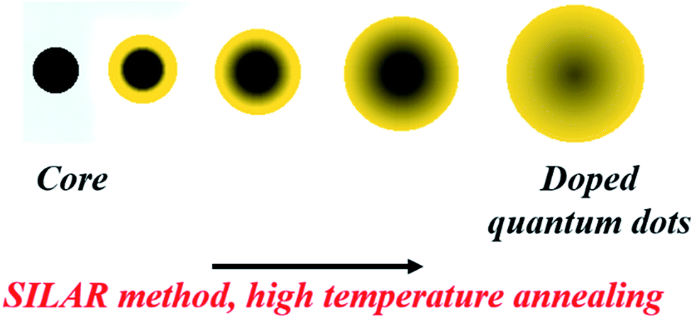
Intentional electronic doping into semiconductor quantum dots has attracted growing interest because impurity ions within the quantum dot (QD) lattice can impart desirable properties, such as optical,1–3 magnetic,4–6 electrical7 and electronic8,9 properties. Also, because of their substantial ensemble Stokes shifts, doped QDs avoid the self-quenching problems of un-doped QDs. These doped dots combine both magnetic and semiconductor properties into a single optoelectronic material; thus, they are excellent candidates for solution-processed photovoltaics,10,11 photodetectors,12–14 light emitting diodes15,16 and spin-photonic applications, especially in the current era of miniaturization of devices to nanoscale dimensions. Doping colloidal QDs with aliovalent elements that can act as electron donors or acceptors is a very promising approach to introduce electrical functionality.17–19 Examples of the properties arising from successful incorporation of impurity ions in the semiconductor matrix include very large Zeeman splittings of excitonic excited states introduced by strong dopant-carrier exchange coupling, red-shifted PL emission bands arising from either the dopant d–d levels or the interaction of the dopant d level with the host, and several other applications.20–24 The unpaired spins of these open shell transition metal dopants are magnetically or optically coupled to the free and photogenerated charge carriers, wherein the dopant-carrier spatial overlap determines the coupling strength. These sp–d exchange interactions are characteristic features resulting in magneto-optical and/or magneto-transport properties.25 In fact, these properties and applications have been extensively studied in the literature and have also been reviewed in several recent reviews.23,26,27 However, further progress of these applications is dependent on the development of reliable methods for effective incorporation of impurities into the semiconductor matrix wherein the dopant ions actually substitute host atoms in the QDs and are not simply adsorbed on the QD surface.Until recently, these properties have been exploited in devices where doped semiconductors are fabricated using molecular beam epitaxy.28 However, colloidal methods for doping semiconductor QDs to produce reliable electronic functionalization, leading to efficient solid-state devices, have attracted significant attention in recent years due to their flexibility of composition, size control and cost-effectiveness.29,30 Further, due to the current interest in miniaturization of devices, the use of smaller functional materials is important. However, this technology is riddled with several problems that arise due to quantum confinement and must be overcome to obtain high-quality materials. This was recognized early on by the research community, and the synthesis of high-quality functional materials has been extensively reported in the literature. Colloidal synthesis is an effective method to produce highly crystalline QDs. Colloidal synthesis was first reported by Murray, Norris and Bawendi for CdS, CdSe and CdTe quantum dots.31 High-temperature colloidal synthesis involves pyrolysis of host precursors at high temperatures in the presence of organic ligands followed by nucleation and growth. The high-temperature annealing of QDs facilitates the formation of defect-free dots. Fig. 1 illustrates a general schematic of the colloidal synthesis of doped QDs wherein the dopant precursor can be added at different time intervals, along with the host precursors, or at the time of nucleation and growth at appropriate temperatures depending upon the diffusivity of the dopant ions.
 | ||
| Fig. 1 Schematic of the general colloidal synthesis of organic ligand-capped doped quantum dots. | ||
In this review, we mainly focus on the different concepts adopted for effective synthesis of doped QDs using the colloidal approach.
2. Challenges in doping
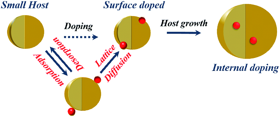
Early attempts to incorporate dopants within QDs included the stoichiometric addition of dopant precursor to the host precursor.32,33 In the colloidal synthesis of QDs, the dopant ions were introduced into the semiconductor matrix using metal–organic precursors or metal-salt precursors; this is significantly different from doping the bulk counterparts, where a pure solid-state reaction at high temperature is used to drive the dopants into the host matrix. However, it was soon realized that it is not possible to seamlessly include dopant ions within the host lattice, although researchers have recently demonstrated the inclusion of high percentages of dopants with appropriate controls using stoichiometric addition.34 While doping these QDs, only a small fraction of the added dopants is incorporated into the crystal lattice, while a large proportion of the dopants remains on the surface or forms clusters.35,36 Energetically, it is more favorable to form clusters of dopant ions, segregate into a separate phase or simply be adsorbed on the host surface. While various characterizations were developed to distinguish between surface-adsorbed ions and those doped into the lattice,37 the success of this method has been limited. Hence, it is also important to design clever techniques to stabilize the metastable phases of the dopant ion within the host lattice.Based on the successes and failures of stoichiometric addition, researchers were largely driven towards understanding the various steps involved in dopant incorporation and subsequent stabilization of the dopant within the lattice. Current understanding of the mechanism of dopant incorporation within QDs using colloidal methods is still largely limited. One early model based on surface kinetics suggests that doping during the growth of the QDs is controlled by adsorption of impurity ions on the surface of the QDs.38 Thus, this is expected to be an extrinsic problem that can be controlled by controlling the kinetics of the QDs. However, it has been observed that impurity ions are thermodynamically unstable inside the host due to the higher formation energy of defects; this indicates the intrinsic difficulty in doping QDs, as exhibited by the self-purification model.39–41 Thermodynamics suggests that the defect formation energy of impurity ions is quite high. However, in solution phase synthesis at low temperatures, kinetics rather than thermodynamics governs the growth of the QDs where the kinetic factors control the dopant incorporation in the host lattice. Recently, Chen et al.42 have studied the various elementary processes involved in the doping of QDs using solution route methods. They identified the presence of four individual processes, namely surface adsorption, lattice incorporation, lattice diffusion and lattice ejection, with a critical temperature characterizing each of the processes, as shown in the schematic in Fig. 2. They further characterize effective doping by suitable programming of reaction temperatures to accommodate all the individual processes. However, due to the involvement of intuitively contrasting processes, generic extension to the synthesis of any QD was largely limited.
 | ||
| Fig. 2 Schematic of temperature-dependent dopant lattice diffusion. | ||
Very recently, it was shown by Saha et al.29,43 that the challenge of doping is highly intricate and involves several thermodynamic factors, such as the diffusion constant of the dopant within the host lattice and the bond dissociation energy of the dopant metal precursor. However, they also showed that the bonding energy of the dopant with the host anion did not play a major role in the systems they studied. In this case, they made constructive use of the self-purification process; hence, the initial adsorption of the dopant ion onto the lattice was not relevant. In fact, although there has been tremendous progress in recent years, uniform doping with desirable compositions remains a challenge in colloidal QDs due to clustering and phase separation; this has motivated the development of new techniques. Researchers are exploring this long-standing problem of introducing impurity ions into QDs, and strategies are beginning to emerge that apply to diverse doping compositions. Here, we enumerate various doping techniques found in the literature along with their achievements and limitations, with an emphasis on recent progress in the development of cluster-free transition metal-doped quantum dots through synthetic engineering of their compositions, sizes, and interfaces.
3. Doping methods
Impurity doping into QDs can be largely classified as extrinsic or intrinsic doping.3.1 Extrinsic doping
The various options involved in extrinsic doping can be mainly divided into charge injection methods and use of appropriate surface ligands to induce functionality into QDs.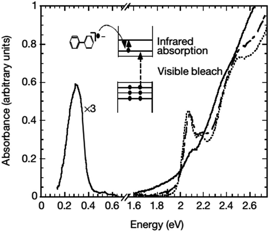 | ||
| Fig. 3 Absorption spectra of CdSe nanocrystals before (dotted line), immediately after (solid line), and 27 hours after (dashed line) the addition of sodium biphenyl reagent. The concurrent optical bleach of the first two exciton transitions and the appearance of infrared absorption can be clearly seen. The blue-shifts of the optical spectra after the disappearance of the infrared absorption suggest that the n-type nanocrystals decompose by the loss of the outermost layer of the semiconductor. Adapted with permission from ref. 44. | ||
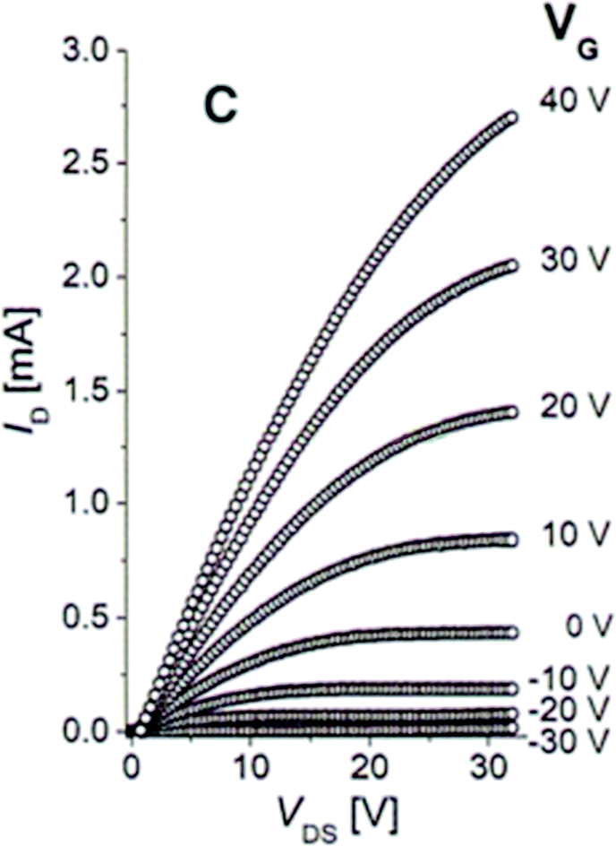 | ||
| Fig. 4 The plot of drain current ID versus drain-source voltage VDS as a function of the gate voltage VG for an FET nanocrystal with a channel composed of 8 nm PbSe nanocrystals treated with hydrazine solution for 12 hours. Adapted with permission from ref. 47. | ||
3.2 Intrinsic doping
Despite these limited successes, extrinsic doping is not a highly feasible option to impart functionalities such as magnetic, optical and optoelectronic functions. Hence, it is important to determine methodologies for efficient intrinsic doping of dopant ions.In order to accommodate the differential reactivities of the dopant and host precursors, they proposed methods to decouple the two by using either nucleation or growth doping in order to effectively dope the QDs, as shown in Fig. 5. In the case of nucleation doping, a small dopant compound was first formed. These core nuclei were then overcoated with a host shell, resulting in graded alloys or sharp interfaces depending on the conditions. However, in the case of growth doping, they demonstrated the formation of small host QDs, followed by surface adsorption of the dopant ion at decreased temperature and addition of the dopant metal precursor. Isocrystalline or hetero-crystalline shells were then grown to encapsulate the dopant ions, demonstrating widespread applicability.1,50 A prototype example of this proposed mechanism was carried out for Cu or Mn-doped ZnSe QDs; as shown in Fig. 6, effective doping and decoupling from nucleation and growth is indicated by the increase of the photoluminescence (PL) intensity of the dopant emission and the decrease in the PL intensity of the host (top, left). Regrowth of ZnSe on the surface of doped QDs results in a redshift of the PL (top, right). The above process would have been difficult to control without the decoupling technique, as it required 100 minutes to complete. However, nucleation doping was realized for Mn-doped ZnSe using different dopant precursors. The Mn2+ precursor is expected to be less reactive than the Zn2+ precursor with the same ligand because Mn2+ is a harder Lewis acid than Zn2+. Zinc acetate was preferable for the formation of MnSe: ZnSe nanocrystals compared to zinc stearate when manganese stearate was used as the precursor for the nucleation step. Zinc stearate required a higher reaction temperature, causing homogeneous nucleation of ZnSe and resulting in band gap PL.
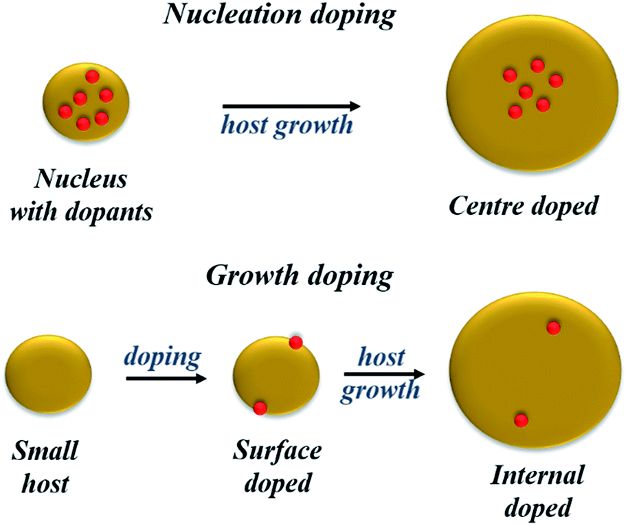 | ||
| Fig. 5 Schematic of the proposed radial positions of the dopant in nucleation- and growth-doping. | ||
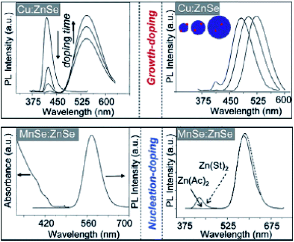 | ||
| Fig. 6 Spectroscopic data for nucleation- and growth-doped QDs. Adapted with permission from ref. 49. | ||
However, the major drawback of this technique is high-temperature annealing during growth of the shell, resulting in the expulsion of dopants; they ultimately leach out of the surface, resulting in self-purification. This was explicitly verified in the case of Cu-doped ZnSe QDs, as shown in Fig. 7. It is evident from the figure that the overcoating at 210 °C contained the dopants within the host lattice without diffusion of dopants from the nucleus to the surface. However, upon annealing at 220 °C or higher, ejection of the dopants from the lattice was observed for all sizes, as shown in Fig. 7A–C. Additionally, with increasing overcoating temperature, significant quenching of the dopant PL was observed upon annealing between 20 °C and 80 °C (Fig. 7C). Thus, overcoating ZnSe at higher temperatures results in dramatic diffusion of Cu dopants towards the surface. Hence, despite extended efforts from various groups on different systems to obtain internally doped QDs, it has not been possible to obtain internally doped QDs.
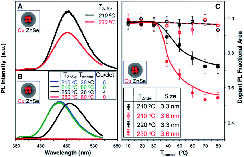 | ||
| Fig. 7 (A) PL spectra of similar-sized Cu-doped ZnSe QDs prepared at different ZnSe overcoating temperatures (TZnSe) of 230 °C and 210 °C. (B) PL spectra of Cu-doped ZnSe QDs with TZnSe of 250 °C and 210 °C and their corresponding spectra after thermal annealing at 80 °C (Tanneal). The inset table shows the number of Cu ions per nanocrystal (Cu/dot) for the four samples. (C) Fractional areas of the Cu dopant PL of the Cu-doped ZnSe QDs as a function of thermal annealing temperature (Tanneal) for different overcoating temperatures and different nanocrystal sizes. The maximum brightness of the Cu dopant PL for each case was set as 1. Adapted with permission from ref. 42. | ||
More recently, Manna et al.51 used the concept of magic-sized metal clusters held together by stable metal–metal bonds to seed the growth of QDs to obtain more uniformly doped QDs. They used clusters composed of four copper atoms (Cu4) capped with D-penicillamine to seed the growth of CdS QDs in water at room temperature, which acts as a quantized source of dopant impurities. While the authors claim that the optical properties of these QDs are insensitive to external and surface changes, the major drawback of this technique is clustering of the dopant ions, leading to the absence of dopant–host interactions, at least within the first shell of atoms. This could have also led to the insensitivity of the doped QDs to external factors. Hence, while uniform dots were obtained from this method, this method also ensures clustering of dopant atoms, albeit limited to the first shell of atoms.
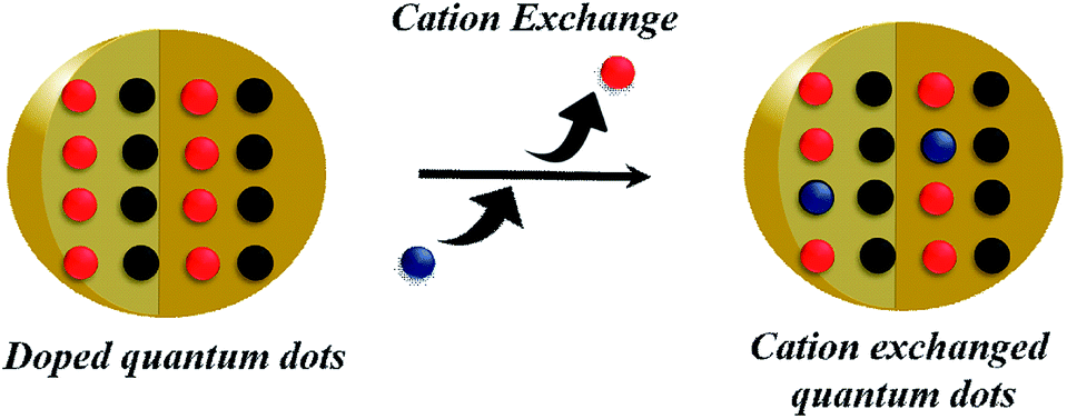
Cation Exchange. Cation exchange reactions are widely applied for doping QDs where the cation of the QDs can be exchanged with a dopant cation.30,54,55 A typical scheme of cation exchange is shown in Fig. 8. TEM images of a specific example of doped nanocrystals, Mn-doped CdSe, are shown in Fig. 9. Varying the solution concentration of the incoming dopant cations and the nature of the ligands attached to them can tune the extent of cation exchange. However, these processes are not trivial in semiconductor QDs, as ascertained by the high energetics involved in doping. Additionally, clustering or directional doping based on reactivity is the inherent nature of this doping technique. While the directional nature has been used constructively to obtain different hetero-structure morphologies, clustering of dopant ions does not enable uniform doping of impurities.56–58
 | ||
| Fig. 8 Schematic of cation exchange. | ||
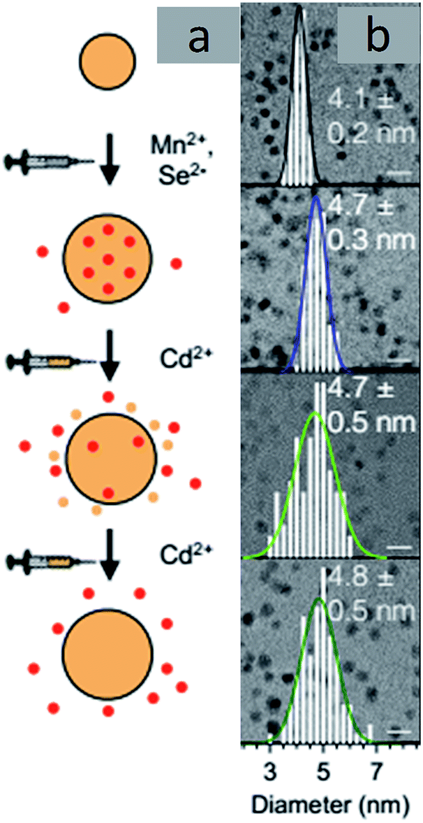 | ||
| Fig. 9 TEM images of Mn-doped CdSe. Adapted with permission from ref. 30. | ||
Diffusion Doping. Diffusion doping, first designed by Saha et al., also exploits the self-purification technique instead of trying to combat this problem, which is usually considered to be a hindrance.29 Here, a small magnetic core was over-coated with a thick shell of the host semiconductor using the SILAR (successive ionic layer adsorption and reaction) technique. Annealing this core–shell structure at a high temperature allows diffusion of the core at the interface and into the semiconductor shell; eventually, it diffuses out of the system. The model system studied by Saha et al. was an Fe3O4 core overcoated with a CdS shell, as shown in Fig. 10. The strained interface with a lattice mismatch of approximately 4% and high-temperature annealing drives the diffusion of the core into the shell with a decrease in the size of the core, ultimately leading to uniformly doped QDs.
 | ||
| Fig. 10 Diffusion of dopants into the CdS matrix to obtain Fe-doped CdS QDs. | ||
The controlled diffusion was achieved by controlling the rate of outward diffusion of the core to be slower than the rate of growth of the semiconductor shell. By controlling parameters such as annealing time and temperature as well as the bond dissociation energy of the core, effective doping was achieved with control over the percentage and uniformity of doping as well as the size of the QDs. Uniform doping has been achieved using different sizes of oxides and sulfide cores. Local structure investigation through XAFS59 and element specific mapping through STEM-EDX confirmed uniform distribution of Fe in the CdS matrix, precluding any cluster formation, as shown in Fig. 11. Thus, this technique has been demonstrated to result in uniformly doped QDs, and QDs of different sizes and dopant concentrations have been obtained using inside out-diffusion. The EDX elemental mapping in Fig. 11d shows clear evidence of the uniform distribution of Fe in the CdS matrix. Fe, Cd and S span the complete area of the nanocrystal, precluding clustering by the Fe3O4 core. Also, visual inspection of Fe and Cd K-edge EXAFS data in real space for Fe3O4 and Fe-doped CdS QDs shows that the local structure around Fe in Fe–CdS is very different from that of Fe in Fe3O4, as shown in Fig. 11e and f. However, the local structure around Fe in Fe–CdS matches well with that of Cd in CdS, implying that the environment around the Cd atom in Fe–CdS is very similar to that of Fe. Also, the absence of a second nearest neighbor Fe–Fe path further verifies the absence of iron oxide clusters. The inset of Fig. 11f shows the XANES spectrum, showing a linear combination of Fe3O4 and FeS paths for the Fe–CdS sample with FeS dominating the contribution. This confirms that Fe has been incorporated into the CdS lattice after undergoing a reduction in oxidation state from +2.66 to +2.
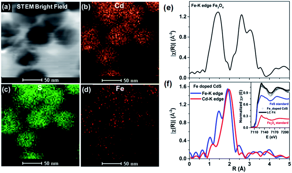 | ||
| Fig. 11 TEM elemental map of Fe-doped CdS showing STEM: (a) bright field image, (b) Cd map, (c) S map, and (d) Fe map. The magnitude of the Fourier-transformed Fe-K edge EXAFS spectra for Fe3O4 (e) and a comparison of Fe and Cd K-edge Fe-doped CdS (f). The linear combination fit (black solid line) of the Fe K-edge XANES spectra with FeS (blue solid line) and FeO standards (red solid line) is shown in the inset. Adapted with permission from ref. 29. | ||
Further, the generality and universality of this technique was established for other dopant ions, such as M2+ (Fe2+, Ni2+, Co2+, Mn2+).43 The effectiveness of inside-out diffusion doping depends on the ability of the core to penetrate into the CdS lattice, followed by the potential of the metal ion to diffuse within the lattice and the ease of cation exchange, as shown in the schematic in Fig. 12.
 | ||
| Fig. 12 Scheme showing the formation of uniformly doped QDs through bond breaking and diffusion of ions inside the CdS matrix during thermal annealing. Adapted from ref. 43. | ||
Effective doping was confirmed through steady-state optical emission spectra and time-resolved photoluminescence spectra at the dopant peaks; as shown in Fig. 13a and b, these dots showed superior properties compared to previous reports. A broad dopant emission peak at a lower energy in the PL steady state is present only in the spectra of the doped CdS samples, suggesting that the emission arises due to dopant states and is not due to surface states. Long-lived time-resolved photoluminescence spectra of the dopant peaks further confirm that the broad emission is due to doped states. This work describes efficient doping of various dopants by controlling thermodynamic parameters; the process is described in three steps, namely diffusion at the interface followed by diffusion of dopant ions within the host matrix and, finally, facile cation exchange.43
 | ||
| Fig. 13 (a) Steady-state PL (solid line) and absorption (dashed line) of Ni2+ (blue), Co2+ (red) and Mn2+ (black)-doped QDs. (b) Lifetime decay plots for Ni2+, Co2+ and Mn2+-doped CdS collected at the maxima of the broad dopant peaks. The inset of (b) shows the enlarged portion of the lifetime decay of the Ni2+ and Co2+-doped CdS. Adapted from ref. 43. | ||
Factors such as differing bond strengths of the cores (sulfides or oxides), diffusing abilities of the dopant ions and ease of cation exchange based on the HSAB effect60 were explored in this work. Here, sulfides of Fe, Mn, Ni, and Co were used as cores because their diffusion into the host CdS lattice is more facile. This highlights their suitability to tailor QDs with required sizes and dopant percentages. This inside-out diffusion doping is thus a promising technique that endows these cluster-free dots with interesting optical and magnetic properties.
A comparison of the various doping techniques for QDs discussed above is provided in Table 1.
| Doping Method | Advantage | Disadvantage | Ref. |
|---|---|---|---|
| Stoichiometric addition of dopant and host precursor | Inclusion of high percentage of dopants | Small portion incorporated, large portion on the surface | 32 and 33 |
| Surface kinetic model | Doping controlled by kinetics | High defect formation energy, self-purification | 38 |
| Thermodynamic model | In solution phase at low temperature, dopant incorporation controlled by kinetics | High defect formation energy | 39 |
| Charge injection method | No expulsion of dopants | Air-accelerated decay, specific, impractical for wide-scale use | 44 and 45 |
| Ligand-modulated QD reduction | Passivates dangling bonds, reduces intermolecular spacing | Unstable nature of Bronsted base | 47 |
| Decoupling nucleation and growth doping | Efficient intrinsic doping | High-temperature expulsion of dopants | 49 |
| Use of magic-sized dopant clusters | Uniform dots | Clustering of dopant ions within the first shell | 51 |
| Cation exchange | Productive use of self-purification | High energetics involved | 55 |
| Diffusion doping | Self-purification as an aid, uniformly doped QDs, control over percentage and size of QDs, universal technique, co-doping | Limited by the penetration capability of the core ions into the host lattice, diffusivity of metal ions in the host lattice, cation exchange | 29,43,61 |
An aspect that has not been greatly addressed in the QD literature is the efficiency of doping as a function of the size of the dots. This is primarily due to the inability to simultaneously control the percentage of doping and the QD size. Although the doping efficiency is not expected to vary greatly in the 3 to 20 nm size regime, this has been studied recently by Saha et al.29,61 using doped QDs obtained using the diffusion doping method. It should also be noted that in this specific case, a long-range size variation of up to 60 nm with 5% Fe doping has been achieved by appropriately tuning the synthesis conditions, allowing the study of doping efficiency in large QDs; this is especially critical for the study of magneto-optical and magnetic properties of QDs.
4. Open challenges
Despite the great progress in the synthesis of doped QDs and the evolution of newer and more facile designs to obtain cluster-free QDs, a major challenge that remains is the study of the absence of clusters. One of the major obstacles in this field is indeed the absence of appropriate characterization techniques to study the internal structures of QDs. The internal structures of QDs face several issues, including surface and internal defects, clusters, and the quality of the interface between the dopant cluster and the host; these are key factors in determining the properties of QDs. For example, it has been extensively demonstrated that the presence of a sharp interface is suitable for a photo-absorbing material in a type II semiconductor.62 Similarly, the presence of a smooth interface between the core and the shell is responsible for substantially increasing the QY of materials63 as well as introducing an exchange bias at the interface of magnetic and non-magnetic materials.64 Similarly, surface defects are known to play important roles in the determination of material properties.65 The radial position of the dopant atom is key to the determination of several optical properties.66 However, these and several other parameters, such as defects, clusters, the interface and the radial position of dopant ions, currently lack suitable characterization techniques to study them.To date, only a few characterization techniques have been able to distinguish between surface doping and lattice incorporation. The location and distribution of dopants has been studied through EXAFS and STEM-EDX by Saha et al. and Chen et al.29,42 Also, by using high-frequency electron paramagnetic resonance (HF-EPR) spectroscopy, the site-dependent perturbation experienced by Mn2+ ions in the CdSe lattice enables distinguishing of the local environments of the Mn2+ ions in the core and the surface of QDs,37 as shown in Fig. 14. The global fitting of the frequency-dependent EPR spectra for the two discrete sextet patterns for a Mn-doped CdSe sample measured at 406.4 GHz allows accurate assignment of the sites.
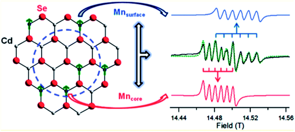 | ||
| Fig. 14 Theoretical fit and deconvolution of the 406.4 GHz HF-EPR spectra allowing assignment of discrete sites for Mn2+ occupying a substitutional Cd2+ site within the core (red) and surface (blue). Adapted with permission from ref. 37. | ||
Variable energy photoemission has been used to study the nature of the interface67 as well as the nature of the surface.68,69 Optical techniques such as the use of the Cu dopant emission mechanism to study the surface of QDs have also been proposed.1 However, most of these techniques are indirect and highly specialized. Also, these techniques are subject to the validity of various models and do not provide a straightforward, easy method to study the radial position of dopants or the presence of clusters. Further, they also require specialized study; thus, they are not very suitable as characterization methodologies.
XRD and TEM are usually insensitive to the presence of small clusters or dopant positions. Hence, the development of a straightforward method to study clustering with atomic resolution would be an important step in advancing the doping of QDs using colloidal synthesis. Secondly, the uniformity of the various QDs obtained during colloidal synthesis can be quite varied; thus, they are not very suitable for high-quality applications. To date, the synthesis of monodisperse ensembles of QDs individually doped with identical numbers of impurity atoms has remained a challenge; its achievement would enable the realization of advanced QD devices, such as optically/electrically controlled magnetic memories and intragap state transistors and solar cells, that rely on precise tuning of the impurity states within the QDs. Additionally, it is very important to design appropriate characterization techniques in order to obtain high-quality QDs doped with the required number of ions.
5. Conclusion
At the heart of many technologies, the impurity dopant ions control the behavior of QDs. These doped materials cultivate excellent properties arising from exchange interactions between the dopant ions and the delocalized charge carriers. The physical effects are further enhanced in these QDs by carrier confinement; these effects have been observed even at room temperature. Much effort is being made experimentally and theoretically70 to obtain QDs with high dopant concentrations and also with single dopant regimes. Careful control of parameters such as the dopant core size, core lattice strength, and temperature can lead to effective doping. The types of dopant precursors and their lattice strengths play a key role in the aforementioned doping technique. Colloidal synthesis is known to be cost-effective and result in uniform QDs where surfactants control the growth and passivate the dangling bonds. Although the controlled incorporation of dopants in QDs has made great strides in recent years, it remains a frontier challenge in doping chemistry. Further, in order to achieve success in these techniques, whether the impurities are effectively incorporated into the lattice or simply adsorbed on the surface, careful characterization of the resulting QDs is required.Conflicts of interest
There are no conflicts to declare.Acknowledgements
The authors thank JNCASR, Sheikh Saqr Laboratory and Department of Science and Technology, Government of India for financial support.Notes and references
- G. K. Grandhi, R. Tomar and R. Viswanatha, ACS Nano, 2012, 6, 9751–9763 CrossRef PubMed.
- R. N. Bhargava, D. Gallagher, X. Hong and A. Nurmikko, Phys. Rev. Lett., 1994, 72, 416–419 CrossRef PubMed.
- D. J. Norris, N. Yao, F. T. Charnock and T. A. Kennedy, Nano Lett., 2001, 1, 3–7 CrossRef.
- K. M. Hanif, R. W. Meulenberg and G. F. Strouse, J. Am. Chem. Soc., 2002, 124, 11495–11502 CrossRef PubMed.
- A. Bonanni and T. Dietl, Chem. Soc. Rev., 2010, 39, 528–539 RSC.
- R. Viswanatha, D. Naveh, J. R. Chelikowsky, L. Kronik and D. D. Sarma, J. Phys. Chem. Lett., 2012, 3, 2009–2014 CrossRef.
- G. S. Shanker, B. Tandon, T. Shibata, S. Chattopadhyay and A. Nag, Chem. Mater., 2015, 27, 892–900 CrossRef.
- A. Sahu, M. S. Kang, A. Kompch, C. Notthoff, A. W. Wills, D. Deng, M. Winterer, C. D. Frisbie and D. J. Norris, Nano Lett., 2012, 12, 2587–2594 CrossRef PubMed.
- G. K. Grandhi, K. Swathi, K. S. Narayan and R. Viswanatha, J. Phys. Chem. Lett., 2014, 5, 2382–2389 CrossRef PubMed.
- C.-H. M. Chuang, P. R. Brown, V. Bulović and M. G. Bawendi, Nat. Mater., 2014, 13, 796–801 CrossRef PubMed.
- G. H. Carey, I. J. Kramer, P. Kanjanaboos, G. Moreno-Bautista, O. Voznyy, L. Rollny, J. A. Tang, S. Hoogland and E. H. Sargent, ACS Nano, 2014, 8, 11763–11769 CrossRef PubMed.
- D. Kufer, I. Nikitskiy, T. Lasanta, G. Navickaite, F. H. L. Koppens and G. Konstantatos, Adv. Mater., 2015, 27, 176–180 CrossRef PubMed.
- G. Konstantatos, M. Badioli, L. Gaudreau, J. Osmond, M. Bernechea, F. P. G. de Arquer, F. Gatti and F. H. L. Koppens, Nat. Nanotechnol., 2012, 7, 363–368 CrossRef PubMed.
- Z. Deng, K. S. Jeong and P. Guyot Sionnest, ACS Nano, 2014, 8, 11707–11714 CrossRef PubMed.
- L. Sun, J. J. Choi, D. Stachnik, A. C. Bartnik, B.-R. Hyun, G. G. Malliaras, T. Hanrath and F. W. Wise, Nat. Nanotechnol., 2012, 7, 369–373 CrossRef PubMed.
- Y. Yang, Y. Zheng, W. Cao, A. Titov, J. Hyvonen, J. R. Manders, J. Xue, P. H. Holloway and L. Qian, Nat. Photonics, 2015, 9, 259–266 CrossRef.
- A. Stavrinadis, J. S. Pelli Cresi, F. d'Acapito, C. Magén, F. Boscherini and G. Konstantatos, Chem. Mater., 2016, 28, 5384–5393 CrossRef.
- C. N. R. Rao, J. Phys. Chem. Lett., 2015, 6, 3303–3308 CrossRef.
- S. R. Lingampalli, K. Manjunath, S. Shenoy, U. V. Waghmare and C. N. R. Rao, J. Am. Chem. Soc., 2016, 138, 8228–8234 CrossRef PubMed.
- S. Delikanli, M. Z. Akgul, J. R. Murphy, B. Barman, Y. Tsai, T. Scrace, P. Zhang, B. Bozok, P. L. Hernández-Martínez, J. Christodoulides, A. N. Cartwright, A. Petrou and H. V. Demir, ACS Nano, 2015, 9, 12473–12479 CrossRef PubMed.
- J. H. Yu, X. Liu, K. E. Kweon, J. Joo, J. Park, K.-T. Ko, D. W. Lee, S. Shen, K. Tivakornsasithorn, J. S. Son, J.-H. Park, Y.-W. Kim, G. S. Hwang, M. Dobrowolska, J. K. Furdyna and T. Hyeon, Nat. Mater., 2010, 9, 47–53 CrossRef PubMed.
- R. Beaulac, L. Schneider, P. I. Archer, G. Bacher and D. R. Gamelin, Science, 2009, 325, 973–976 CrossRef PubMed.
- M. Makkar and R. Viswanatha, Curr. Sci., 2017, 112, 1421–1429 CrossRef.
- C. J. Barrows, V. A. Vlaskin and D. R. Gamelin, J. Phys. Chem. Lett., 2015, 6, 3076–3081 CrossRef PubMed.
- J. K. Furdyna, J. Appl. Phys., 1988, 64, R29–R64 CrossRef.
- D. Bera, L. Qian, T.-K. Tseng and P. H. Holloway, Materials, 2010, 3, 2260–2345 CrossRef.
- P. Wu and X.-P. Yan, Chem. Soc. Rev., 2013, 42, 5489–5521 RSC.
- F. X. Xiu, Z. Yang, L. J. Mandalapu, D. T. Zhao, J. L. Liu and W. P. Beyermann, Appl. Phys. Lett., 2005, 87, 152101–152103 CrossRef.
- A. Saha, A. Shetty, A. R. Pavan, S. Chattopadhyay, T. Shibata and R. Viswanatha, J. Phys. Chem. Lett., 2016, 7, 2420–2428 CrossRef PubMed.
- C. J. Barrows, P. Chakraborty, L. M. Kornowske and D. R. Gamelin, ACS Nano, 2016, 10, 910–918 CrossRef PubMed.
- C. B. Murray, D. J. Norris and M. G. Bawendi, J. Am. Chem. Soc., 1993, 115, 8706–8715 CrossRef.
- R. Viswanatha, S. Sapra, S. Sen Gupta, B. Satpati, P. V. Satyam, B. N. Dev and D. D. Sarma, J. Phys. Chem. B, 2004, 108, 6303–6310 CrossRef PubMed.
- N. Murase, R. Jagannathan, Y. Kanematsu, M. Watanabe, A. Kurita, K. Hirata, T. Yazawa and T. Kushida, J. Phys. Chem. B, 1999, 103, 754–760 CrossRef.
- B. Bhattacharyya, K. Gahlot, R. Viswanatha and A. Pandey, J. Phys. Chem. Lett., 2018, 9, 635–640 CrossRef PubMed.
- M. van Schilfgaarde and O. N. Mryasov, Phys. Rev. B, 2001, 63, 233205 CrossRef.
- K. Sato, H. Katayama -Yoshida and P. H. Dederichs, Jpn. J. Appl. Phys., 2005, 44, L948–L951 CrossRef.
- W. Zheng, Z. Wang, J. Wright, B. Goundie, N. S. Dalal, R. W. Meulenberg and G. F. Strouse, J. Phys. Chem. C, 2011, 115, 23305–23314 CrossRef.
- R. Buonsanti and D. J. Milliron, Chem. Mater., 2013, 25, 1305–1317 CrossRef.
- S. C. Erwin, L. Zu, M. I. Haftel, A. L. Efros, T. A. Kennedy and D. J. Norris, Nature, 2005, 436, 91–94 CrossRef PubMed.
- N. S. Karan, S. Sarkar, D. D. Sarma, P. Kundu, N. Ravishankar and N. Pradhan, J. Am. Chem. Soc., 2011, 133, 1666–1669 CrossRef PubMed.
- G. M. Dalpian and J. R. Chelikowsky, Phys. Rev. Lett., 2006, 96, 226802 CrossRef PubMed.
- D. Chen, R. Viswanatha, G. L. Ong, R. Xie, M. Balasubramaninan and X. Peng, J. Am. Chem. Soc., 2009, 131, 9333–9339 CrossRef PubMed.
- A. Saha, M. Makkar, A. Shetty, K. Gahlot, A. R. Pavan and R. Viswanatha, Nanoscale, 2017, 9, 2806–2813 RSC.
- M. Shim and P. Guyot-Sionnest, Nature, 2000, 407, 981–983 CrossRef PubMed.
- M. Shim, C. Wang and P. Guyot-Sionnest, J. Phys. Chem. B, 2001, 105, 2369–2373 CrossRef.
- D. Yu, C. Wang and P. Guyot-Sionnest, Science, 2003, 300, 1277–1280 CrossRef PubMed.
- D. V. Talapin and C. B. Murray, Science, 2005, 310, 86–89 CrossRef PubMed.
- M. V. Kovalenko, M. I. Bodnarchuk, J. Zaumseil, J. S. Lee and D. V. Talapin, J. Am. Chem. Soc., 2010, 132, 10085–10092 CrossRef PubMed.
- N. Pradhan, D. Goorskey, J. Thessing and X. Peng, J. Am. Chem. Soc., 2005, 127, 17586–17587 CrossRef PubMed.
- G. K. Grandhi and R. Viswanatha, J. Phys. Chem. Lett., 2017, 8, 2043–2048 CrossRef PubMed.
- B. Santiago -González, A. Monguzzi, V. Pinchetti, A. Casu, M. Prato, R. Lorenzi, M. Campione, N. Chiodini, C. Santambrogio, F. Meinardi, L. Manna and S. Brovelli, ACS Nano, 2017, 11, 6233–6242 CrossRef PubMed.
- J. B. Rivest and P. K. Jain, Chem. Soc. Rev., 2013, 42, 89–96 RSC.
- Z. Deng, L. Tong, M. Flores, S. Lin, J.-X. Cheng, H. Yan and Y. Liu, J. Am. Chem. Soc., 2011, 133, 5389–5396 CrossRef PubMed.
- D. H. Son, S. M. Hughes, Y. Yin and A. P. Alivisatos, Science, 2004, 306, 1009–1012 CrossRef PubMed.
- B. J. Beberwyck, Y. Surendranath and A. P. Alivisatos, J. Phys. Chem. C, 2013, 117, 19759–19770 CrossRef.
- R. D. Robinson, B. Sadtler, D. O. Demchenko, C. K. Erdonmez, L.-W. Wang and A. P. Alivisatos, Science, 2007, 317, 355–358 CrossRef PubMed.
- B. Sadtler, D. O. Demchenko, H. Zheng, S. M. Hughes, M. G. Merkle, U. Dahmen, L.-W. Wang and A. P. Alivisatos, J. Am. Chem. Soc., 2009, 131, 5285–5293 CrossRef PubMed.
- D. O. Demchenko, R. D. Robinson, B. Sadtler, C. K. Erdonmez, A. P. Alivisatos and L.-W. Wang, ACS Nano, 2008, 2, 627–636 CrossRef PubMed.
- A. Saha, S. Chattopadhyay, T. Shibata and R. Viswanatha, J. Phys. Chem. C, 2016, 120, 18945–18951 CrossRef.
- R. G. Pearson, J. Chem. Educ., 1968, 45, 581 CrossRef.
- A. Saha and R. Viswanatha, J. Phys. Chem. C, 2017, 121, 21790–21796 CrossRef.
- A. Saha, S. Chattopadhyay, T. Shibata and R. Viswanatha, J. Mater. Chem. C, 2014, 2, 3868–3872 RSC.
- A. Saha, K. V. Chellappan, K. S. Narayan, J. Ghatak, R. Datta and R. Viswanatha, J. Phys. Chem. Lett., 2013, 4, 3544–3549 CrossRef.
- A. Saha and R. Viswanatha, ACS Nano, 2017, 11, 3347–3354 CrossRef PubMed.
- J. Tang, K. W. Kemp, S. Hoogland, K. S. Jeong, H. Liu, L. Levina, M. Furukawa, X. Wang, R. Debnath, D. Cha, K. W. Chou, A. Fischer, A. Amassian, J. B. Asbury and E. H. Sargent, Nat. Mater., 2011, 10, 765–771 CrossRef PubMed.
- A. Pandey and D. D. Sarma, Z. Anorg. Allg. Chem., 2016, 642, 1331–1339 CrossRef.
- P. K. Santra, R. Viswanatha, S. M. Daniels, N. L. Pickett, J. M. Smith, P. O'Brien and D. D. Sarma, J. Am. Chem. Soc., 2008, 131, 470–477 CrossRef PubMed.
- S. Sapra, J. Nanda, J. M. Pietryga, J. A. Hollingsworth and D. D. Sarma, J. Phys. Chem. B, 2006, 110, 15244–15250 CrossRef PubMed.
- J. Nanda, B. A. Kuruvilla and D. D. Sarma, Phys. Rev. B, 1999, 59, 7473 CrossRef.
- M.-H. Du, S. C. Erwin and A. L. Efros, Nano Lett., 2008, 8, 2878–2882 CrossRef PubMed.
| This journal is © The Royal Society of Chemistry 2018 |