
 Open Access Article
 This Open Access Article is licensed under a Creative Commons Attribution-Non Commercial 3.0 Unported Licence
Fabrication of 3D conductive circuits: print quality evaluation of a direct ink writing process
F. Tricot *a,
C. Venetb,
D. Beneventia,
D. Curtila,
D. Chaussya,
T. P. Vuongc,
J. E. Broquinc and
N. Reverdy-Bruasa
*a,
C. Venetb,
D. Beneventia,
D. Curtila,
D. Chaussya,
T. P. Vuongc,
J. E. Broquinc and
N. Reverdy-Bruasa
aInstitute of Engineering, Univ. Grenoble Alpes, CNRS, Grenoble INP, LGP2, F-38000 Grenoble, France. E-mail: fanny.tricot@grenoble-inp.fr
bSchneider Electric, France
cInstitute of Engineering, Univ. Grenoble Alpes, CNRS, Grenoble INP, IMEP LAHC, F-38000 Grenoble, France
First published on 19th July 2018
Abstract
The use of conductive inks and direct writing techniques for the fabrication of electronic circuits on complex substrates is attracting ever increasing interest. However, the existing knowledge is only focused on the electrical performances of the produced smart objects with no direct correlation with the conductive paths morphology and printing conditions. In order to evaluate the printing quality of a direct writing process using an eccentric screw dispenser, a printing device for the deposition of silver paste on 3D objects was developed. Lines of different widths were printed on flat PC + ABS substrates by means of the developed printing device and a conventional screen printing process. The developed process permitted printing lines as thin as possible with screen printing but with a better regularity of their edges. However unlike screen printed lines, the thickness of the lines was dependent on their width. Finally, the possibility to print on 3D objects was demonstrated.
Introduction
As a consequence of the lightning development of the Internet and network technologies over the past few decades, the Internet of Things (IoT), which deals with the interconnection of devices and their interactions with humans, is a hot topic for modern society.1 There is a drive for new capabilities, like sensors, actuators, and communication functions, to be incorporated in daily objects. This is leading to the development of new technologies combining mechanical and electronical functions to produce interconnected systems.2 One such system that is increasingly proving to be attractive in several fields, such as automotive,3,4 medical5,6 and telecommunications,7,8 is three-dimensional moulded interconnected devices (3D-MID).9 This requires additional steps in the fabrication of thermoplastic objects to incorporate electrical components in or at the surface of the object. To date, two processes are industrially available. They both need specific thermoplastics and chemical treatments for metallizing, which requires substantive investment.10 On the one hand, the two-shot moulding consists of two successive injection mouldings, one of a non-plateable thermoplastic to constitute the object and one of a plateable thermoplastic to pre-form the electric elements.11 On the other hand, the second technique involves laser direct structuring (LDS), developed by LPKF Laser & Electronics AG, which is based on the injection-moulding of a thermoplastic charged with metallic precursors. Once the object has been patterned by moulding, a laser is used to selectively activate the conductive areas.3 Finally, for both processes, a chemical metallization is performed to achieve the fabrication of electric elements.10To propose an alternative to both two-shot moulding and LDS techniques, some research groups have focused on additive manufacturing thanks to the emergence of 3D printing techniques. The latter offers indeed polyvalent and cost-effective solutions since it does not require specific materials and allows avoiding chemical metallization. Several articles report the adjustment of low cost12,13 or home-made14,15 3D printers based on a fused deposition modelling (FDM) process. The printing substrate can be a thermoplastic product,12–14,16 a wafer17 or a glass slide.17 It can be either previously made by other techniques14,17 or produced within the FDM process12,13 as the conductive elements are deposited. The latter are fabricated by the selective coating of conductive inks, mostly silver paste.14,16,17 To do this, the FDM extruder is usually replaced by a dispenser composed of a syringe filled with the ink. The conductive material is pushed through a needle to be ejected thanks to the air pressure.14,15,17 One article reports the use of a dispenser composed of an eccentric screw driving the ink towards the needle.18 That fabrication process is mainly used to incorporate a wireless communication function to the objects.12,13,16 In all readings, the evaluation of the fabricated product is considered from an electrical and communicating performance point of view.
This paper proposes to evaluate the deposition process inspired by FDM 3D printing as a printing process. The aim was to discuss the quality of the printing made by the 3D writing process on a thermoplastic substrate commonly used for the manufacturing of daily objects in comparison with the printing quality obtained by a conventional printing techniques (i.e. screen printing).
To set up the study, a commercial screen printing silver ink was printed according to a lines design on 2D PC + ABS substrates by two means: the standard screen printing process and the developed direct ink writing method. The ink behaviour during the two processes was first considered. Then, the characteristics of the printed lines were determined and compared.
Experimental
Materials
Substrates on which the prints were performed were supplied by Schneider Electric SA in the form of 80 × 80 × 3 mm3 PC + ABS thermoplastic plates with a surface roughness Ra of 643 ± 20 nm (as determined with an Alicona InfiniteFocus optical profilometer). This type of thermoplastic material, which cannot withstand temperatures higher than 110 °C, was selected because it is abundantly used in consumer goods manufacturing. Because of these substrate characteristics, the main properties considered to choose the conductive ink were a drying temperature inferior to 110 °C and a compatibility with solvent-sensitive substrates. The ability of printing ultrafine lines was not taken into account. The silver ink Electrodag 418SS from Henkel was used since it satisfied the substrate requirements. According to the technical data sheet, an ink layer of 25 μm leads to a resistivity inferior to 750 nΩ m and the ink solid content is 66.5% with a silver particle size D50 lower than 8 μm and D95 below 24 μm. No treatment was done on the surface of the substrates before printing.Printing
- Squeegee pressure: 7 kg for a squeegee (70–75 shore) of 350 mm length.
- Squeegee speed: 10 mm s−1.
- Off contact: 4 mm.
After printing, the lines were dried at 110 °C for 20 min.
(1) A Cartesian 3D printer Prusa i3 rework 1.5 (EmotionTech) controlled by an Arduino Mega 2560/Ramps 1.4 board and Repetier software.
(2) An accurate volumetric dosing system (Ecopen 300 Preeflow provided by Viscotec). The device comprised two elements: the printing head, which looks like a pen, and a controller. In this system, the ink to print is stored in a pressurized external syringe and it is pneumatically fed into the printing head, which constitutes a soft polymeric stator and a stainless steel eccentric screw. The rotation of the endless screw brings the ink to the extremity of the stator, where a needle is fixed. The fluid is then pushed through the needle to reach the surface to print. The internal diameter Øinternalneedle (μm) of the used needle was chosen in accordance with the size of particles contained in the ink. The controller was linked at the Ecopen head by an electronic wired connection, which permits managing the ink flow rate Q (μL min−1) in the printed head and starting/stopping the printing.
The two described devices were assembled to form the 3D printing process used in this study. For this, the original FDM printing head of the 3D printer was replaced by the Ecopen connected to its controller. An electronic wired connection was made between the Ecopen controller and the Arduino board in order to synchronise ink dispensing (on a start/stop basis) with the XYZ motion of the 3D printer. Fig. 1(a) presents a photograph of the device and Fig. 1(b) illustrates the ink route in the Ecopen printed head.
 | ||
| Fig. 1 (a) Photograph of the developed printing device, (b) schema of the Ecopen head and route of the ink flow. The ink is represented in grey colour. The route is represented by the red arrow. | ||
For all the studies, the distance between the needle and the surface to print zecopen (μm) was fixed according to the internal diameter of the needle. Table 1 summarizes the parameters for which the effect of their variation on the printed pattern was studied.
| Parameters | Q (μL min−1) | V (mm min−1) | zecopen (μm) | Øinternalneedle (μm) |
|---|---|---|---|---|
| Values | 5–100 | 150–1000 | =Øinternalneedle | 110 & 200 |
The first study consisted in evaluating the effect of the fluid flow rate on the printed pattern. For that, the moving speed of the 3D printer v (mm min−1) was monitored to a level just inferior to the ink speed in the Ecopen. Besides, it had to be inferior to 1000 mm min−1 to avoid printing defects due to mechanical vibrations of the 3D printer. The average ink speed in the dispensing needle was estimated using eqn (1):
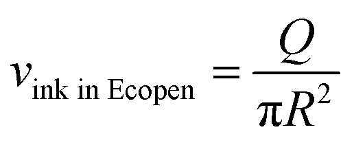 | (1) |
After printing, the lines were dried at 110 °C for 90 min.
With the developed printing device lines, the associated speed and dispensing on/off switch were both directly programmed in g-code or drawn using CAD software and converted into a g-code using Repetier/Slicer.
Characterizations
Rotational rheological experiments were performed to simulate the ink behaviour during the two studied printing processes.
On the one hand, the ink was submitted to the following successive shear rate values: 1 s−1—150 s/1000 s−1—60 s/1 s−1—150 s. This procedure imitates the screen printing process. The first step corresponds to the ink being on the screen, the second step represents the passing of the ink through the screen during the squeegee stroke and the third step simulates the remaining ink being deposited on the substrate.19–21
On the other hand, the ink flow in the volumetric pump was simulated by four steps using the following assumptions:
- First, the passage of the ink in the eccentric screw was represented by a low shear rate of 1 s−1 during 150 s.
- Second, the needle was assimilated to a tube and the ink behaviour was preliminary estimated by a power law.22 The passage of the ink through the needle was characterized by the maximal shear rate at the walls of the needle, given by eqn (2):22
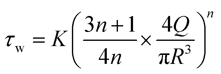 | (2) |
- Third, during the deposition of the ink on the substrate, the ink is supposed to be between a fixed plane (the substrate) and a mobile plane in translation (the needle). The shear rate was calculated using eqn (3):
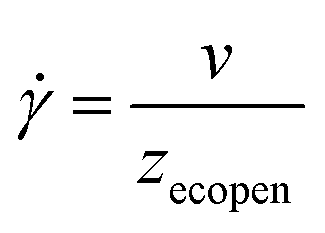 | (3) |
![[small gamma, Greek, dot above]](https://www.rsc.org/images/entities/i_char_e0a2.gif) (s−1) is the shear rate and v (m s−1) and zecopen (m) are the parameters used during the experiment.
(s−1) is the shear rate and v (m s−1) and zecopen (m) are the parameters used during the experiment.
- Fourth, a period of rest was imposed with a shear rate at 1 s−1 during 150 s.
Oscillatory measurements were also carried out to characterize the viscoelastic properties of the ink. A frequency of 1 Hz was selected. Beforehand, the linear viscoelastic area (LVE) was determined. This represents the region where the fluid displays a solid viscoelastic behaviour.23 Here, the stress is too weak to break particles network and the ink behaves as a hooked spring. A procedure representative of the screen printing process was applied. It was composed of three steps. During the first and the third, an oscillatory stress of 0.1 Pa, including in the LVE area, was applied during 150 s. This simulated the deposition of the ink on the screen before the squeegee stroke and the ink deposited on the substrate after printing. The second step was characterized by an applied oscillatory stress (3000 Pa) beyond the LVE area in order to simulate the breaking of the ink structure during the squeegee stroke. The phase angle δ (°) was measured during the oscillatory experiment. This represents the phase difference between the applied sinusoidal stress and the response of the fluid and indicates the predominant behaviour, elastic, or viscous, since its tangent is equal to the quotient of the loss modulus on the storage modulus.24,25 Here, a phase angle of 0° corresponds to a solid material, whereas a value of 90° is a characteristic of a liquid.19,20
All the measurements were repeated at least twice. For each measurement, a new sample of ink was considered.
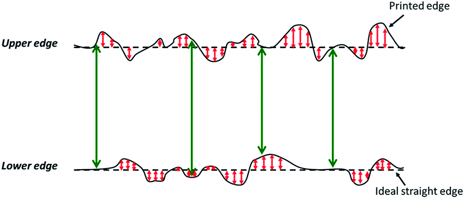 | ||
| Fig. 2 Drawing of the top view of a printed line (continuous line) and the corresponding ideal line (dashed line). The red arrow represents the standard deviation calculated between the edge of the printed line and the edge of the corresponding ideal line. This calculation was made for each pixel on the printed edges. The green arrow represents the calculated width of the printed line. The calculation was made pixel by pixel. | ||
The thickness and the roughness of the printed lines were measured using an Alicona InfiniteFocus optical profilometer (magnification ×10 and ×50). Roughness measurements followed the ISO 4288 standard. For each printing condition, 15 to 25 thickness and roughness measurements were done. The adhesion of lines on the substrate was evaluated with the tape test, following the ISO 2409-2007 2013 standard.
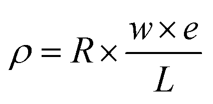 | (4) |
Results and discussion
Ink rheological behaviour during the printing processes
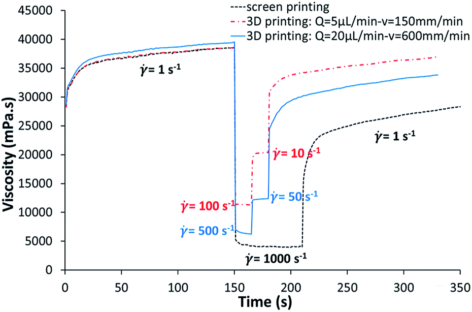 | ||
| Fig. 3 Rheological behaviour of the Henkel ink during the simulation of printing processes. | ||
Regardless of the specific process simulation, 150 s after printing, the ink recovered a lower viscosity value than the initial one, depending on the applied maximal shear rate. Here, 95% of the viscosity value was recovered after a succession of shearing at 100 then 10 s−1, whereas only 73% was reached after shearing at 1000 s−1. Consequently, the ink tended to spread on the substrate after printing. Because of that behaviour, the studied ink was not suitable for printing fine lines.27 The spreading coefficient appeared to be dependent on the intensity of the shearing and has to be taken into account during the determination of the printing parameters in order to respect the expected size of patterns.
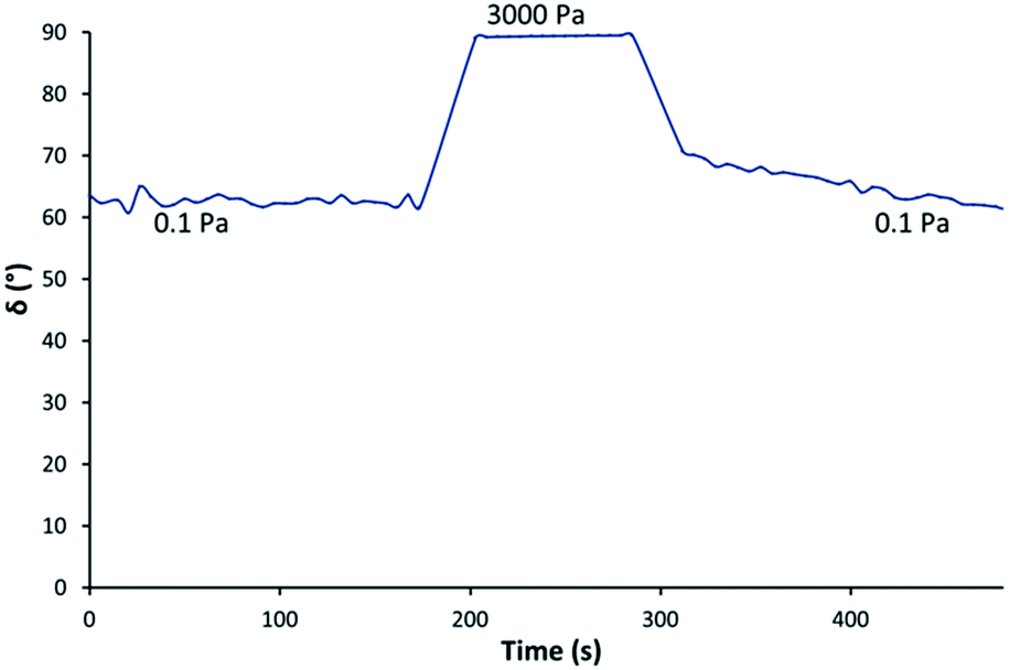 | ||
| Fig. 4 Evolution of the phase angle δ during screen printing simulation in an oscillatory regime. | ||
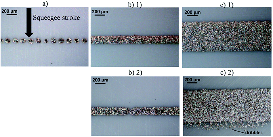 | ||
| Fig. 5 Photographs of screen printed lines: (a) 50 μm theoretical width line, (b) 100 μm theoretical width line: (1) without defect, (2) with a lack of ink, (c) 500 μm theoretical width line: (1) without defect and (c) (2) with dribbles at the lower edge. | ||
- Non-continuous lines for targeted widths of 50 μm.
- Continuous lines of 100 μm theoretical width with some punctual lacks of ink.
- The presence of dribbles at the lower edge of some horizontal lines for targeted widths larger than 200 μm.
In the literature, some papers report the printing of continuous lines of 3028 and 50 μm29–31 widths. The authors of those papers explain that to obtain these resolutions some precautions were necessary. Mainly, the ink rheology and the properties of the screen had to be adapted to fine lines. In this paper, on the one hand, the study of the ink rheological behaviour showed that it is not adapted to produce fine lines. On the other hand, the screen was produced according to the recommendation of the technical data sheet of the ink and not to fit with the properties that would permit achieving fine lines. As the emulsion thickness was 30 μm, the emulsion over mesh was higher than 10 μm, thus restricting the printing resolution.30 The diameter of threads constituting the fabric was about 40 μm, while according to DEK recommendations, the minimal line width equals three times the thread diameter. Producing fine lines requires an advanced screen printing process. However, the objective of this paper was to demonstrate the ability of a new 3D printing process to print on a commonly used solvent-sensitive and poor thermal-resistant plastic substrate with a quality similar to that achieved by a standard screen printing process. Therefore, the printing of continuous fine lines was not in the scope of the present study.
The presence of dribbles at the lower edge of some horizontal continuous lines was attributed to the orientation of the lines with respect to the squeegee. This observation can be explained either by a screen deformation leading to a widening of the pattern or by the passing of a part of the ink below some threads of the fabric because of the complete liquid-like behaviour previously demonstrated. This last phenomenon was less observable on vertical lines because the ink spread below the fabric threads could be hidden by the line itself, which was perpendicular to the squeegee and hence parallel to its displacement. The production of repeatable and well-defined lines was therefore dependent on their orientation with respect to the squeegee.
Some lines profiles were reconstructed from observations and measurements with the optical profilometer. An example of the reconstruction of a horizontal line is presented in Fig. 6. According to the 3D view presented in Fig. 6(a), the line is visually regular and no significant defect is observable. The profile of the cross-section presented in Fig. 6(b) approaches a pulse function due to the principle of the screen printing process where the ink passes through opened meshes. The width and the thickness of the line were in agreement with the results presented in the following sections. Similar observations were done on other printed lines.
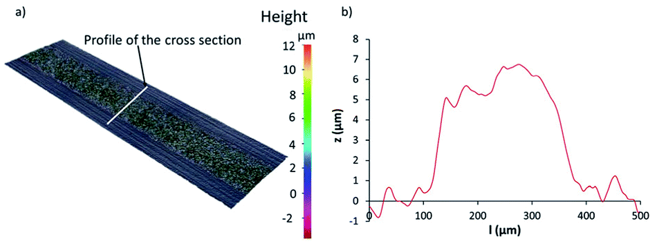 | ||
| Fig. 6 (a) 3D view of a screen printed horizontal line with a theoretical width of 200 μm, (b) profile of the cross-section of the printed line presented in (a). | ||
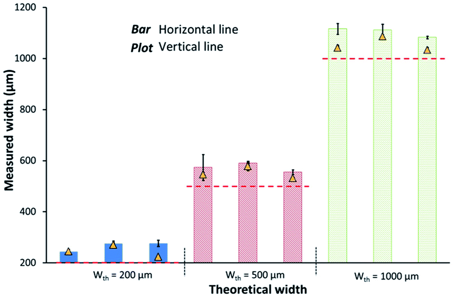 | ||
| Fig. 7 Average widths of 3 printed lines/condition according to theoretical width values and the line orientation. | ||
| Targeted width (μm) | 200 μm | 500 μm | 1000 μm |
|---|---|---|---|
| Widening (%) | 30% | 12% | <10% |
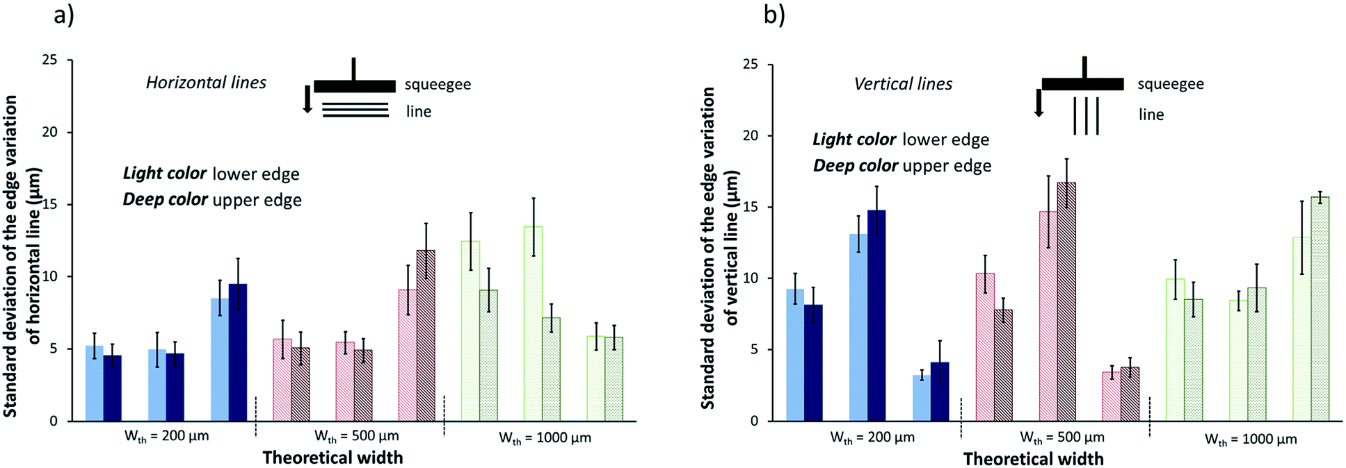 | ||
| Fig. 8 Average standard deviation of the variation of the lower and upper edges of lines for targeted widths of 200, 500, and 1000 μm: (a) 3 horizontal lines/conditions, (b) 3 vertical lines/conditions. | ||
For all the studied lines, the recorded standard deviations were lower than 17 μm. The highest amplitude of edge variations was therefore about 32 μm. The relevance of taking into account the highlighted edge variations was therefore dependent on the line width. Indeed, those variations represent 12% of the width for a 200 μm targeted width, whereas they only correspond to less than 5% of the measured width of a line with a targeted width of 1000 μm.
Finally, the characterization of screen printed lines showed that:
- The spreading of the ink leads to a widening of the targeted width. The thinner the line, the stronger this effect is.
- The orientation of the line with respect to the squeegee impacts both the formation of dribbles at the lower edge and the regularity of line edges.
Characteristics of the lines printed with the 3D printing technique
Using the screen printed lines as a reference, lines were drawn thanks to the volumetric dispenser fixed on the 3D printer. The printing parameters relative to the dispenser, i.e. the fluid flow rate Q (μL min−1) and the inner diameter of the needle Øneedle, (μm), and relative to the moving table, i.e. the moving speed v (mm min−1), were the parameters under investigation. The obtained lines were characterized and compared to the screen printing ones.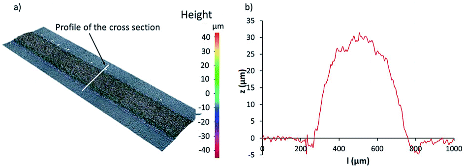 | ||
| Fig. 9 (a) 3d view of a line printed with the developed process with the following conditions: needle with a 200 μm inner diameter, Q = 5 μL min−1, v = 150 mm min−1, (b) profile of a cross-section of the line presented in (a). | ||
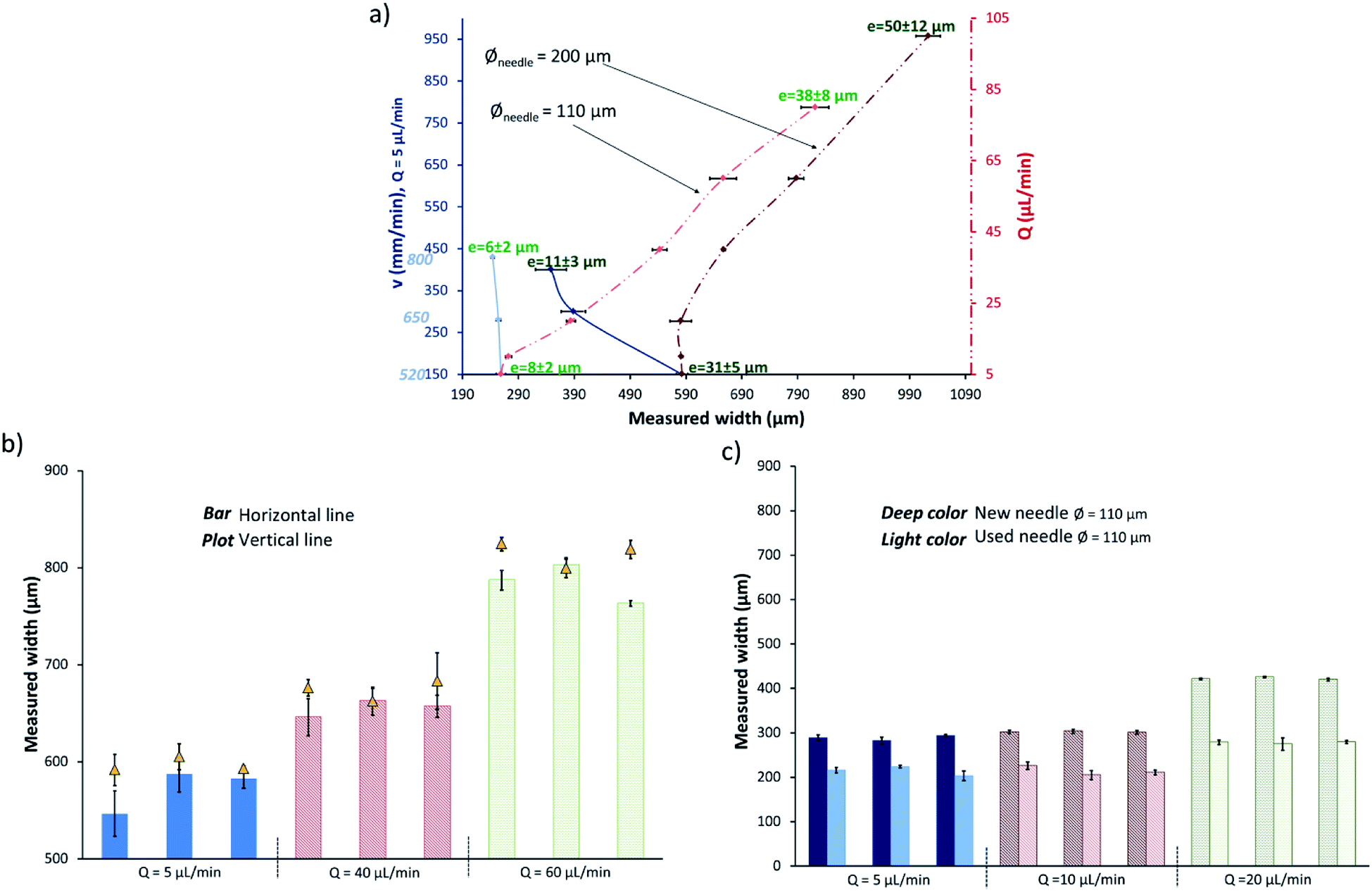 | ||
| Fig. 10 Line widths according to the printing parameters: (a) horizontal lines width versus fluid flow, speed and inner needle diameter. The e value is the measured thickness, (b) width comparison of horizontal and vertical lines printed with a needle of inner diameter 200 μm, (c) width comparison between several printings with the same 110 μm inner diameter needle. | ||
According to Fig. 10(b), the vertical lines show a slightly higher width than horizontal lines for the same printing parameters. The orientation of lines only changes the part of the device that is moving. When printing vertical lines, the dispenser was motionless, while the substrate placed on the 3D printer table was moving. On the contrary, the dispenser was moving and the substrate was motionless for writing horizontal lines.
Otherwise, the reproducibility of the developed process when considering a 200 μm inner diameter needle is highlighted in Fig. 10(b). Indeed, three lines by the set of writing parameters were printed at different times and the measured widths did not present significant differences.
Finally, Fig. 10(c) highlights the limitations entailed by the use of a needle with an inner diameter of 110 μm. Such a needle cannot be used to print several sets of lines without observing a reduction of the lines widths. This phenomenon could be due to a partial clogging of the needle with silver micro-particles. However, this limitation can be overcome by using an ink with smaller silver particles, but this should not be assigned to the process itself.
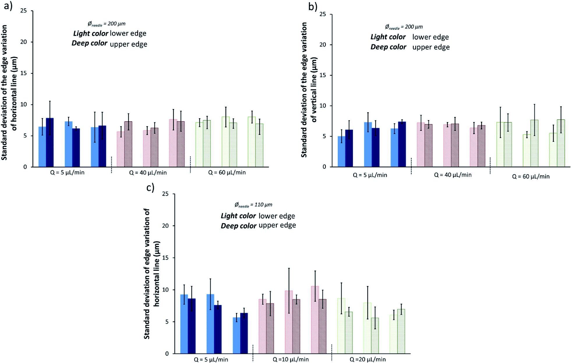 | ||
| Fig. 11 Average standard deviation of the variation of lower and upper edges of lines printed with the modified 3D printing process: (a) 3 horizontal lines/condition printed with a 200 μm inner diameter needle, (b) 3 vertical lines/condition printed with a 200 μm inner diameter needle, (c) 3 horizontal lines printed with a 110 μm inner diameter needle. | ||
By comparing graphs (a) and (b) with graph (c) in Fig. 11, it appears that the edges regularity is affected by the use of the needle with a small inner diameter. This can also be explained by an eventual partial clogging of the needle, which could be solved by using an ink with smaller particles.
Concerning the adhesion, the tape test led to the same result as the one obtained with screen printing. This property is actually mainly driven by the affinity between the ink and the substrate and the printing process does not impact this phenomenon.
Finally, the study of the lines printed with the 3D printing device showed that:
- A similar range of widths than the ones obtained with a standard screen printing process can be reached with the 3D-written process. However, printing lines with a width inferior to 350 μm requires a frequent change of needle. Nevertheless, this limitation can be overcome by selecting ink with smaller silver particles.
- The lines printed with the developed process have more regular edges than those produced by screen printing.
- The thickness of the lines is dependent on the deposited quantity. Large lines cannot present the same thickness than thinner lines.
- The line orientation does not affect the quality of the printed lines.
- The surface roughness of 3D-written lines is twice the roughness of the screen printed ones.
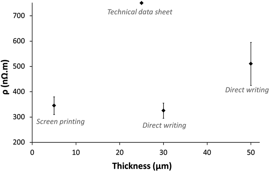 | ||
| Fig. 12 Average resistivity of screen printed and direct written lines according to their thickness, and comparison with the data of the technical data sheet of the ink. | ||
According to Fig. 12, the resistivity of the lines seems to be dependent on the line thickness. As has been demonstrated before, the thickness of lines printed with the developed 3D printing technique is dependent on the printing parameters. Therefore large lines dried at 110 °C, owning a high thickness, had a lower electrical performance than fine lines with a low thickness. This could be explained by a partial drying of the ink above a given thickness value. However, this limitation cannot be assigned to the direct writing method itself without studying the impact of the curing process and its optimisation. This point is the topic of another study.
Despite the previous observation, whatever the characteristics of the printed line, its resistivity was at least 1.5 time inferior to the expected value according to the ink' technical data sheet. Both studied printing techniques combined with a thermal curing at 110 °C are therefore compatible with electrical applications needing performances in accordance with the specifications of the conductive ink used in this study.
Printing on 3D objects
The developed device constituted by an eccentric screw dispenser and a Cartesian 3D printer allowed printing lines with a similar quality to ones obtained with a conventional screen printing system. Since the goal of the present study was to develop a process that could allow printing conductive lines on 3D objects, a few proof of concept systems were realized and tested (Fig. 13).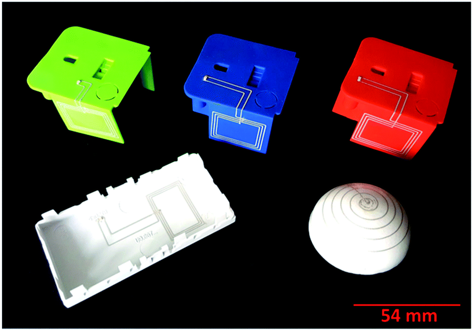 | ||
| Fig. 13 Examples of prints of Henkel ink on thermoplastic 3D objects thanks to the developed device. | ||
Three objects with different shapes were used as model substrates:
- Three coloured PC + ABS items containing 90° converging surfaces (on the top of the picture). The objective was to demonstrate the ability to print a continuous line along two perpendicular planes.
- A curved PC + ABS surface (on the bottom left of the picture). The direct writing permitted depositing a continuous line following the curve of the surface.
- An ABS hemisphere (on the bottom right of the picture) allowing verifying the writing on a spherical surface.
The conductivity of printed tracks was assessed by two means. First, the series resistance of the printed tracks was measured on the coloured items and on the curved one. The resistance value was about 7 Ohm (300 nΩ m). When considering an antenna pattern with L × w × e dimensions of about 400 × 0.58 × 0.028 mm3. Second, when a source was approached to the printed RFID receptor, the provided power entailed a switching of the LED connected to the printed tracks, showing straightforwardly the correct behaviour of the 3D printed circuit.
Conclusion
A direct writing printing device was set up and evaluated by comparing the quality of the printed lines with the ones obtained by a standard screen printing procedure.First, the study demonstrated the following key points:
(1) The direct writing process is compatible with commercial screen printing inks since the shear thinning behaviour of the latter facilitates the deposition step.
(2) The deposition ability of conductive patterns to adhere on to the thermoplastic substrates usually used in industry was confirmed.
(3) The direct writing method permitted printing patterns with a similar quality to the standard screen printing process. Some improvements were observed since line dribbles, typical of screen printing, were not observed. The printing quality was not sensitive to the pattern orientation.
(4) The conductivity of direct written lines after a drying in oven at 110 °C during 90 min was better than the announced value in the technical data sheet. The writing process could be used to produce electronical functions for which the ink specifications were sufficient. Moreover, that result could be improved by optimizing the ohmic curing. This is the topic of an ongoing study.
Second, two other observations deserve to be highlighted:
(1) The direct writing process permits saving ink. Indeed, even if the lines thickness is higher than the one of screen printed lines, only the required quantity is delivered by the volumetric dispenser while, in screen printing, a part of the ink remains on the screen meshes after the squeegee stroke.
(2) Some developments of the process are under further consideration. First, the printing speed can be easily improved by considering a more robust frame to support the printing head. Second, a greater degree of freedom can be envisaged for the printing head. Third, as advanced screen printing has been developed to be able to print ultrafine lines, a study on the ink properties and the printing parameters may cause the deposition of ultrafine lines on 3D objects.
Taking into account all these considerations and the demonstration of the printing on 3D objects, the 3D printing solution investigated can be seen as a viable alternative to the already available MID production techniques. For today, this satisfies the required quality to implement some electronic functions, such as antenna, in daily objects. In the near future, the developments under consideration will permit integrating fine and complex circuitry in any 3D object.
Conflicts of interest
There are no conflicts of interest to declare.Acknowledgements
This work was made within the industrial chair MINT supported by the partnership Foundation of Grenoble INP and for which Schneider Electric is a sponsor. The study was realised at the LGP2 laboratory. LGP2 is part of the LabEx Tec 21 (Investissements d'Avenir – grant agreement no. ANR-11-LABX-0030) and of PolyNat Carnot Institute (Investissements d'Avenir – grant agreement no. ANR-16-CARN-0025-01). This research was made possible thanks to the facilities of the TekLiCell platform funded by the Région Rhône-Alpes (ERDF: European regional development fund).Notes and references
- J. Gubbi, R. Buyya, S. Marusic and M. Palaniswami, Future Gener. Comput. Syst., 2013, 29, 1645–1660 CrossRef.
- W. Xu, Adv. Mech. Eng., 2012, 2, 10 Search PubMed.
- N. Heininger, W. John and H.-J. Bossler, in International Congress MID, 2004 Search PubMed.
- C. Goth and M. Romer, Position sensor for adaptive speed control, (accessed May 19, 2017).
- A. Islam, H. N. Hansen and N. Giannekas, CIRP Ann. Manuf. Technol., 2015, 64, 539–544 CrossRef.
- C. Goth and M. Romer, Optics carrier and heating element for the diagnosis of caries, (accessed May 19, 2017).
- F. Sonnerat, R. Pilard, F. Gianesello, D. Gloria, F. Le Pennec, C. Person, P. Brachat and C. Luxey, in 2013 IEEE Antennas and Propagation Society International Symposium (APSURSI), IEEE, 2013, pp. 2217–2218 Search PubMed.
- N. Heininger, T. P. Mansikkamäki, M. Kivikoski and I. Y.-H. Lee, in Proceedings of International Symposium on Antennas and Propagation, Korea, 2005 Search PubMed.
- A. Housden and J. Gould, Moulded Interconnect Devices, Prime Faraday Partnership, 2002 Search PubMed.
- F. Jorg, Three Dimensional Molded Interconnected devices (3D MID), Hanser Gardner Publications, 2014 Search PubMed.
- M. Pfeffer, C. Goth, D. Craiovan and J. Franke, in 2011 IEEE International Symposium on Assembly and Manufacturing (ISAM), IEEE, 2011, pp. 1–6 Search PubMed.
- M. Ahmadloo and P. Mousavi, in 2013 IEEE MTT-S International Microwave Symposium Digest (IMS), IEEE, 2013, pp. 1–3 Search PubMed.
- C. Mariotti, M. M. Tentzeris and L. Roselli, in Microwave Symposium (MMS), 2015 IEEE 15th Mediterranean, IEEE, 2015, pp. 1–4 Search PubMed.
- F. A. H. Kim, S. B. H. Yun, I. Lee and others, in 2015 15th International Conference on Control, Automation and Systems (ICCAS), IEEE, 2015, pp. 1964–1968 Search PubMed.
- P. K. Wright, D. A. Dornfeld, A. Chen, C. C. Ho and J. W. Evans, Trans. NAMRISME, 2010, 38, 555–561 Search PubMed.
- N. Arnal, T. Ketterl, Y. Vega, J. Stratton, C. Perkowski, P. Deffenbaugh, K. Church and T. Weller, IEEE MTT-S International Microwave Symposium in 2015, IEEE, 2015, pp. 1–4 Search PubMed.
- B. Y. Ahn, D. J. Lorang and J. A. Lewis, Nanoscale, 2011, 3, 2700 RSC.
- R. Ludwig, N.-C. Lee, S. R. Marongelli, S. Porcari and S. Chhabra, Proc. Nepcon West 99 Conf., Technical Session, 1999, vol. 13, pp. 576–588 Search PubMed.
- S. Thibert, J. Jourdan, B. Bechevet, D. Chaussy, N. Reverdy-Bruas and D. Beneventi, Mater. Sci. Semicond. Process., 2014, 27, 790–799 CrossRef.
- F. Hoeng, A. Denneulin, N. Reverdy-Bruas, G. Krosnicki and J. Bras, Appl. Surf. Sci., 2017, 394, 160–168 CrossRef.
- M. Neidert, W. Zhang, D. Zhang and A. Kipka, in Photovoltaic Specialists Conference, 2008. PVSC'08. 33rd IEEE, IEEE, 2008, pp. 1–4 Search PubMed.
- R. P. Chhabra and J. F. Richardson, Non-Newtonian flow in the process industries: fundamentals and engineering applications, Butterworth-Heinemann, 1999 Search PubMed.
- R. Faddoul, N. Reverdy-Bruas and A. Blayo, Mater. Sci. Eng., B, 2012, 177, 1053–1066 CrossRef.
- P. Hahne, E. Hirth, I. E. Reis, K. Schwichtenberg, W. Richtering, F. M. Horn and U. Eggenweiler, Sol. Energy Mater. Sol. Cells, 2001, 65, 399–407 CrossRef.
- C. P. Hsu, R. H. Guo, C. C. Hua, C.-L. Shih, W.-T. Chen and T.-I. Chang, J. Polym. Res., 2013, 20(277), 1–8 Search PubMed.
- H.-W. Lin, C.-P. Chang, W.-H. Hwu and M.-D. Ger, J. Mater. Process. Technol., 2008, 197, 284–291 CrossRef.
- J. Hoornstra, A. W. Weeber, H. H. De Moor and W. C. Sinke, The importance of paste rheology in improving fine line, thick film screen printing of front side metallization, Netherlands Energy Research Foundation ECN, 1997 Search PubMed.
- M. Aoki, K. Nakamura, T. Tachibana, I. Sumita, H. Hayashi, H. Asada and Y. Ohshita, 30 μm fine line printing for solar cells, IEEE Photovoltaic Specialists Conference, Florida, 2013, pp. 2162–2166 Search PubMed.
- R. Soukup, A. Hamáček and J. Řeboun, in 2012 35th International Spring Seminar on Electronics Technology (ISSE), IEEE, 2012, pp. 19–24 Search PubMed.
- D. Erath, A. Filipović, M. Retzlaff, A. K. Goetz, F. Clement, D. Biro and R. Preu, Sol. Energy Mater. Sol. Cells, 2010, 94, 57–61 CrossRef.
- W. J. Hyun, E. B. Secor, M. C. Hersam, C. D. Frisbie and L. F. Francis, Adv. Mater., 2015, 27, 109–115 CrossRef PubMed.
| This journal is © The Royal Society of Chemistry 2018 |