
 Open Access Article
 This Open Access Article is licensed under a Creative Commons Attribution-Non Commercial 3.0 Unported Licence
Galvanic corrosion of duplex corrosion-resistant steel rebars under carbonated concrete conditions
Jinyang Jiang *a,
Hong-yan Chu*b,
Yao Liua,
Danqian Wanga,
Dong Guoc and
Wei Suna
*a,
Hong-yan Chu*b,
Yao Liua,
Danqian Wanga,
Dong Guoc and
Wei Suna
aSchool of Materials Science and Engineering, Southeast University, Nanjing 211189, China. E-mail: jiangjinyang16@163.com
bCollege of Civil Engineering, Nanjing Forestry University, Nanjing 210037, China. E-mail: chuhongyan@njfu.edu.cn
cNaval Institute of Engineering Design and Research, PLA, Beijing 100070, China
First published on 4th May 2018
Abstract
Galvanic corrosion between two different kinds of steel rebars is usually the case in practical engineering. Open circuit potential (OCP), linear polarization resistance (LPR), Tafel polarization, scanning vibrating electrode technique (SVET), scanning electron microscopy (SEM) and reflection digital holographic microscopy (DHM) were used to study the galvanic corrosion of a novel corrosion-resistant steel bar (CR) and low-carbon steel bar (LC) in simulated concrete pore solutions with different pH values and a chloride ion concentration of 5 mol L−1. The pH of the simulated concrete pore solution had a significant impact on the corrosion behaviour of CR and LC when they were in contact and were attacked by chloride ions. As the pH increased, the potential between CR and LC decreased and the driving force for the galvanic corrosion decreased. When the pH was 9.0, galvanic corrosion occurred on CR and LC at a high rate. CR developed local pitting corrosion, while LC mainly developed uniform corrosion, each with an apparent accumulation of corrosion products on the sample's surfaces. When the pH was 11.3, galvanic corrosion occurred when CR and LC were in contact. CR showed a relatively smooth surface, with only a small amount of pitting corrosion. In contrast, LC developed both pitting corrosion and uniform corrosion, and both apparent pitting corrosion and an accumulation of corrosion products on the sample surface were observed. When the pH was 13.6, there was no galvanic corrosion when CR and LC were in contact; the corrosion of CR and LC was mainly pitting corrosion. Therefore, for regions with chloride ion corrosion and severe carbonization, the galvanic corrosion between CR and LC cannot be ignored.
Introduction
Currently, reinforced concrete is one of the most widely used construction materials, due to its high mechanical resistance and economical manufacturing.1,2 Research has shown that chloride ions and the carbonization of concrete are the main causes of the corrosion of rebars,3 which mainly contributes to the degeneration of the concrete's structure.4–6 Developing novel corrosion resistant rebars is an effective approach to fundamentally avoid this corrosion and improve the durability of reinforced concrete. In practical engineering, mixed use of novel corrosion resistant rebars and low carbon steel rebars is usually the case. For example, steel alloys with excellent corrosion resistance are normally used for the longitudinal bar of the concrete, whereas low carbon steel is normally used for stirrups. Thus, contact between corrosion resistant rebars and regular rebars exists and an electron channel forms due to the potential difference between these two kinds of steel. As a result, galvanic corrosion between these two kinds of steel occurs with concrete acting as the electrolyte. These differences are particularly pronounced when carbonization and chloride ion corrosion occur in concrete.The passivation and corrosion of low carbon steel has been investigated for decades,7,8 while the passivation and corrosion mechanism of novel corrosion resistant steel rebars is still in discussion. Ai et al.9 investigated the corrosion performance of alloyed corrosion-resistant rebars in simulated concrete pore solutions with different pH values. For the corrosion-resistant rebar, the lower the alkalinity of the solution is, the easier the steel is passivated and the better the corrosion-resistant properties of the rebar will be. In contrast, for regular low-carbon steel, the lower the alkalinity of the solution is, the more difficult the passivation is and the poorer the corrosion-resistant properties of the rebar will be. Jiang et al.10 studied the formation mechanism of the passive film on a new corrosion-resistant steel in a simulated concrete pore solution. Shi et al.11 investigated the influence of chloride concentration and pre-passivation on the pitting corrosion resistance of low-alloy reinforcing steel in a simulated concrete pore solution. When the chloride ion concentration reached 1.0 mol L−1 in the simulated concrete pore solution, the low-alloy reinforcing steel exhibited better corrosion performance than low-carbon steel. Only two-dimensional microstructure of rebar subjected to different simulated concrete pore solution was investigated in these studies.
Up to now, although there are many reports on the corrosion behaviour of alloy steels in simulated concrete pore solutions, there are only a few reports about the galvanic corrosion that probably occurs when low-carbon steel and alloy steel are used together. Dong et al.12 investigated the galvanic corrosion of stainless steel and showed that the galvanic corrosion and self-corrosion of carbon steel were reinforced in the sand-containing solution. Krogstad et al.13 examined the corrosion behaviour of galvanically coupled Nickel-Aluminium Bronze (NAB) and stainless steel during three weeks of exposure to natural seawater and showed that the galvanic current was limited by the cathodic efficiency of stainless steel, while the coupled potential was dictated by the NAB. Abreu et al.14 studied the galvanic coupling between carbon steel and austenitic stainless steel in sodium hydroxide solution. No significant risk of galvanic corrosion of carbon steel and stainless steel exists under the passivation of steel or chloride ion corrosion. Ai et al.15 studied the adsorption behaviour of anionic inhibitor on galvanic electrode in NaCl solution, and they pointed out that the galvanic corrosion of N80/S31803 can be inhibited by anionic inhibitor. The galvanic current densities between the individual aluminium alloys and the carbon fibre composites were measured by Liu et al.,16 and the experimental results indicated that a higher coupling current density was significant for the AA1050 alloy compared to the AA7075-T6 alloy. Zhang et al.17 carried out an investigation on CO2 corrosion behavior of carbon steel with imidazoline-based inhibitor subjected to NaCl solution, and they found that the H steel (coarse laminar pearlite) suffered more severe localized corrosion than T steel (globular and shot rod shaped pearlite), because the larger driving force for galvanic corrosion. At present, the galvanic corrosion of different metals under the interaction of a single factor has been investigated. However, there are almost no studies about the probable galvanic corrosion of alloy steel and regular, low-carbon steel in the presence of both carbonization and chloride corrosion. As a novel corrosion-resistant rebar, information on microstructure, open circuit potential (OCP), linear polarization resistance (LRP), and Tafel curves of galvanic corrosion between corrosion-resistant rebar and ordinary rebar is rather limited, and needs to be updated.
In the present report, the macroscale corrosion of new corrosion-resistant rebar (CR) and ordinary rebar (LC) in simulated concrete pore solutions with different pH's under the attack of chloride ions was tested. The microscale distribution of the current density in the electrochemical reaction between CR and LC was also investigated in the work. Both the surface morphology and the surface elemental compositions of the rebars were analysed, and the three-dimensional morphology of the rebar surface from the micro- and nano-scales was studied in the paper. The galvanic corrosion of the novel, corrosion-resistant rebar and ordinary rebar in simulated concrete pore solutions with different pH's under the attack of chloride ions was thus investigated.
Experimental section
Raw materials
Comparative investigations were conducted between new Cr10Mo1 corrosion-resistant alloy steel (CR) bar and low-carbon steel (LC) bar. The chemical composition of two kind of steels is shown in Table 1.| C | Si | Mn | Cr | Mo | Fe | |
|---|---|---|---|---|---|---|
| LC | 0.22 | 0.53 | 1.44 | — | — | 97.81 |
| CR | 0.01 | 0.49 | 1.49 | 10.36 | 1.16 | 86.49 |
The simulated concrete pore solution is primary affected by its chemical composition and pH,18 but there are no uniform standards for the preparation of the simulated concrete pore solution. The simulated concrete pore solution used in the work is shown in Table 2. In order to consider the effect of carbonation, the simulated concrete pore solution with different pH was prepared, namely, 9.0, 11.3, and 13.6. For convenience, the three different simulated concrete pore solutions were marked as LA, MA, and HA in Table 2, which denoted weakly alkaline (pH = 9.0), moderately alkaline (pH = 11.3), and highly alkaline (pH = 13.6) of solution, respectively. Chloride penetration into concrete is the main cause of steel corrosion,19 and passive film on the surface of steel bar is destroyed due to chloride ion when the chloride concentration is higher than that of critical chloride concentration of steel bar.20–22 According to our previous study, the critical chloride concentration of CR steel bar is 5 mol L−1. Thus, a high concentration (5 mol L−1) of chloride ion in the simulated pore solution was used in the study so as to accelerate the corrosion of the CR steel. According to Table 2, the simulated concrete pore solutions were prepared with vacuum filtration by utilizing a 2.5 μm filter to ensure that the solutions are free from suspensions.
| Composition | KOH mol L−1 | NaOH mol L−1 | Ca(OH)2 mol L−1 | Na2CO3 mol L−1 | NaHCO3 mol L−1 | pH | NaCl mol L−1 |
|---|---|---|---|---|---|---|---|
| LA | 0 | 0 | 0 | 0.025 | 0.025 | 9.0 | 5 |
| MA | 0.6 | 0.2 | 0.03 | 0 | 0.83 | 11.3 | 5 |
| HA | 0.6 | 0.2 | 0.03 | 0 | 0 | 13.6 | 5 |
Experimental methods
The specimens were immersed in the simulated concrete pore solutions with different pH for 72 h, and then the corrosion behaviour of bars were measured by OCP, LPR, and Tafel polarization. The electrochemical test was performed with the PARSTAT 4000 electrochemical workstation. A three-electrode measurement system was used; i.e., the reinforced bars were set as the working electrode, the saturated calomel electrode was set as the reference electrode, and the platinum electrode was the auxiliary electrode. The test was performed at room temperature (25 ± 1 °C). All electrochemical tests were performed after the open potentials working electrode was stabilised. The range of the linear polarisation resistance is ±10 mV vs. Ecorr at a scanning speed of 10 mV min−1. The potentiodynamic current–potential curves were recorded by polarizing the specimen to −250 mV cathodically and +250 mV anodically with respect to OCP at a scan rate of 0.5 mV s−1. It should be pointed out that the galvanic coupling related to the SEVT testing was simulated by mounting in epoxy resin one new corrosion-resistant steel rod nest to one low-carbon steel rod, with about a 2 mm gap between them. At the rear of the mounting, an electrical connection was made with Sn welding.
Results and discussion
Electrochemical test
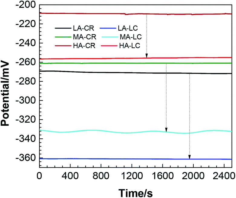 | ||
| Fig. 1 Open circuit potentials of the two steel bars in different solutions (the labels LA, MA, and HA denote which solution the CR or LC is immersed in). | ||
It can be seen from Fig. 1 that the open circuit potentials of CR and LC attacked by chloride ions in simulated concrete pore solutions with different pH all exhibited stable states. When the pH was 9.0, the stable open circuit potentials of CR and LC were approximately −270 mV and −360 mV, respectively. When the pH was 11, the stable open circuit potentials of CR and LC were approximately −260 mV and −330 mV, respectively. When the pH was 13.6, the stable open circuit potentials of CR and LC were approximately −210 mV and −256 mV, respectively. At the same pH, the OCP of CR was always lower than that of LC, and the corrosion thermodynamic tendency of LC was always greater than that of CR.23 As a result, in the galvanic coupling of CR and LC, LC serves as the anode and CR as the cathode. Additionally, with increasing pH, electrode reversal does not occur. Additionally, Fig. 1 shows that with increasing pH, the difference between the OCPs of the steel bars decreased, indicating that the driving force for the galvanic corrosion also decreased.24 In particular, when the pH was 13.6, the difference between the OCPs of CR and LC was only 50 mV. In theory, this constitutes a driving force for galvanic corrosion between them. However, the tendency of galvanic corrosion is low, and the corrosion probably will not occur.
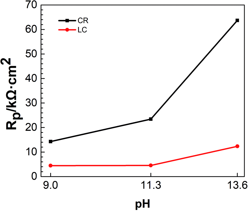 | ||
| Fig. 2 Linear polarization resistances of the two steel bars in simulated concrete pore solutions with different pH. | ||
It can be seen from Fig. 2 that under the attack of chloride ions and at the same pH, the linear polarization resistance of CR was greater than that of LC, indicating that the corrosion resistance of CR is better than that of LC. It can also be seen from Fig. 2 that with increasing pH, the linear polarization resistance of CR and LC increased to different extents. Additionally, the difference between the linear polarization resistance of CR and LC also increased, suggesting that the corrosion resistance of the two steel bars was improved with increasing pH and that the improvement in the corrosion resistance of CR was even more pronounced. This is mainly because when the chloride ion concentration was 5 mol L−1, the passivation of CR and LC was enhanced with increasing pH.9 Furthermore, even if the passivation film of CR is destroyed in highly alkaline environments and under chloride ion penetration, CR can still self-repair. In contrast, LC has very poor self-repair capabilities.25
 | ||
| Fig. 3 Tafel curves of the two steel bars in simulated concrete pore solutions with different pH: (a) pH = 9.0; (b) pH = 11.3; (c) pH = 13.6. | ||
It can be seen from Fig. 3 that the anode zones of each polarization curve exhibited active dissolution characteristics and the cathode zones were controlled by ionization of oxygen and oxygen diffusion. At the same pH, when the Tafel curve of LC was used as a reference, the Tafel curve of CR shifted up and to the left. When the pH = 9.0, the shapes of the cathode polarization curves of LC and CR are similar, indicating that the cathodic corrosion kinetic processes are the same. For the anodic polarization part, CR exhibited features characteristic of pitting corrosion. The balance potential of LC was lower than that of CR, indicating that LC had a greater corrosion tendency. When the pH = 11.3, for the cathodic polarization part of the curve, both LC and CR exhibited a certain degree of concentration polarization, whereas for the anode polarization part, LC exhibited features characteristic of corrosion acceleration and pitting corrosion. The polarization curve of LC markedly shifted to the right, leading to an increased corrosion rate. When the pH = 13.6, the polarization curves of CR and LC were similar and the cathode exhibited features characteristic of pitting corrosion.
Table 3 shows the electrochemical corrosion parameters obtained from fitting the Tafel curves.
| Ecorr/mV | icorr/μA | ba/mV dec−1 | bc/mV dec−1 | |
|---|---|---|---|---|
| LA-CR | −601.277 | 1.18 | 290.435 | 136.875 |
| LA-LC | −707.976 | 2.192 | 163.839 | 99.463 |
| MA-CR | −496.251 | 0.38 | 219.214 | 159.672 |
| MA-LC | −613.031 | 1.258 | 316.974 | 118.594 |
| HA-CR | −443.543 | 0.123 | 165.278 | 161.204 |
| HA-LC | −477.152 | 0.358 | 217.836 | 182.683 |
It can be seen from Table 3 that at the same pH, the Ecorr of LC was smaller than that of CR. Galvanic corrosion is related to the Ecorr of metals. The greater the difference between the Ecorr of the two metals, the more the high-potential cathode is protected and the more easily the low-potential anode is corroded. Therefore, there is a known tendency for galvanic corrosion to occur when LC and CR are in contact. Additionally, LC (as the anode) corrodes first while CR (as the cathode) is protected. The difference between the Ecorr of the two electrodes was approximately 100 mV when the pH was 9.0 and approximately 30 mV when the pH was 13.6. These results showed that with increasing pH, the difference between the Ecorr of LC and CR decreased and the driving force of the galvanic corrosion between the two electrodes decreased. Table 3 shows that, at the same pH, the icorr of LC was greater than that of CR and that CR exhibited better corrosion resistance than LC. With increasing pH, the icorr of both CR and LC decreased, indicating that CR and LC exhibited improved corrosion resistance with increasing pH. For example, the icorr of CR and LC was smallest when the pH was 13.6, suggesting that CR and LC are resistant to corrosion under these conditions. Table 3 shows that ba > bc for CR and LC, indicating that the anodic reaction is the controlling step in the overall reaction of CR and LC.
Fig. 3 and Table 3 show that when galvanic corrosion occurs, it is determined by both the cathodic polarization of CR and the anodic polarization of LC. Reduction occurred on the CR cathode, i.e. O2 + 2H2O + 4e− → 4OH−, whereas the oxidation of metals was developed on the LC anode, i.e. Fe–2e− → Fe2+. Under alkaline conditions, Fe2+ reacted with OH− in the solution to generate Fe(OH)2. Because oxygen was not removed from the solution, the generated Fe(OH)2 was rapidly oxidized by O2 dissolved in the solution to generate Fe(OH)3, which was then rapidly decomposed to Fe2O3.
Fig. 3 and Table 3 show that at the same cathodic polarization potential, higher pH values produced lower current densities on CR. This occurs because higher pH values enhanced the passivation of the steel bar surface and decreased the concentration of oxygen that penetrated the oxidized film to reach the sample surface and participate in the cathodic reaction. As a result, the current density decreased. For LC, at the same anodic polarization potential, higher pH values decreased the current density because the increased concentration of OH− in the solution increased the accumulation of corrosion products on the surface of the electrodes, which affected the dissolution and diffusion rates of cations in the anodic process and thus decreased the reaction rate. As a result, the current density decreased. Because the rates of the reactions on the LC and CR surfaces are controlled by the anodic reaction, when galvanic corrosion occurs between CR and LC, the overall electrochemical reaction of the galvanic electrodes is controlled by the dissolution and diffusion rates of the cations, and the corrosion rate of the galvanic couple decreases with increasing pH.
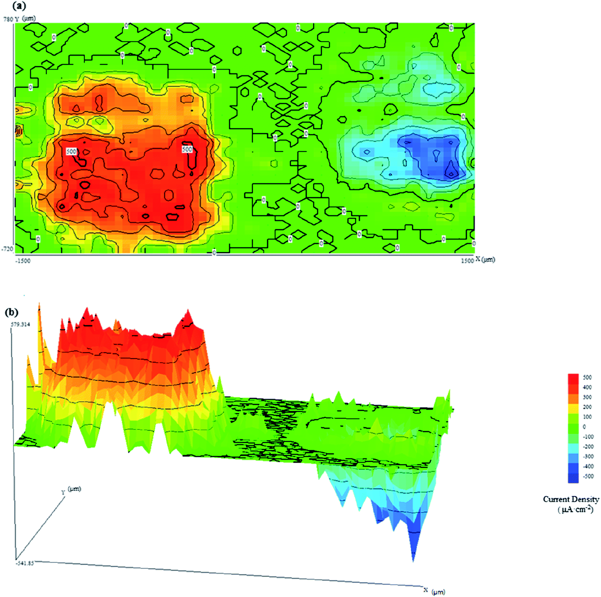 | ||
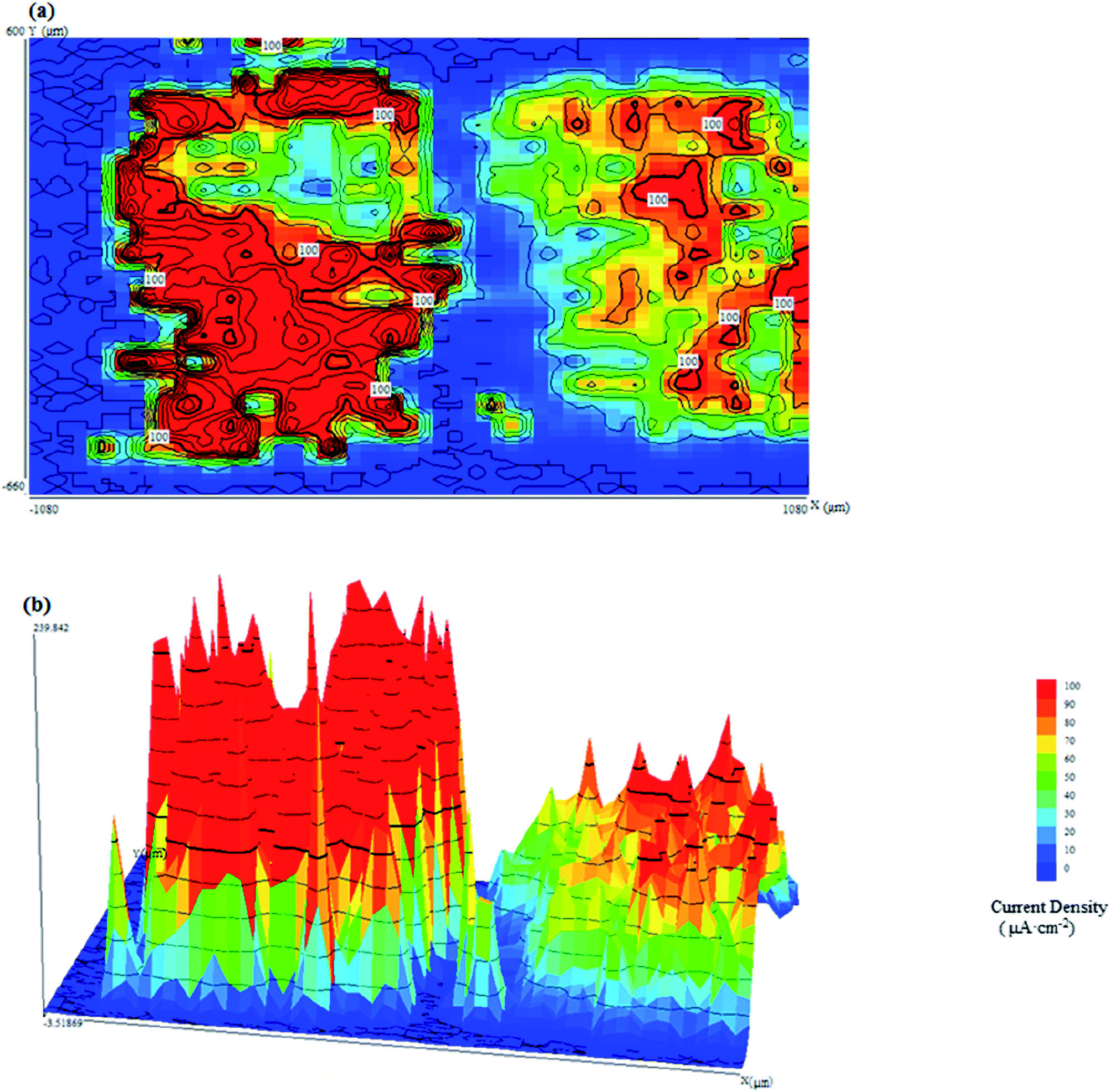
| Fig. 4 SVET current density maps when CR and LC are connected at pH = 9.0 in (a) two-dimensions and (b) three-dimensions. | ||
It can be seen from Fig. 4 that there are two corresponding peaks in the current density map. As predicted, galvanic corrosion occurred on LC and CR, with LC serving as the anode and CR serving as the (protected) cathode. Due to the oxidation reaction and the release of metal cations from the surface of LC, its current density was positive.26 In contrast, due to the reduction reaction and the formation of hydroxide ions on the surface of CR, its current density was negative. As seen from Fig. 4(a), the current densities at CR and LC were approximately 500 μA cm−2. However, the current distribution of the anode and cathode regions did not possess the same characteristics: the current on the surface of LC was uniformly distributed, while that of CR exhibited local differences. Additionally, Fig. 4(b) shows that the uniform current density distribution on LC and the sharp current density peaks on CR are probably attributable to the attack of dissolved chloride ions on their surfaces.
Fig. 5 shows the SVET current density maps of CR and LC when they are in contact at pH = 11.3, including (a) two-dimensional and (b) three-dimensional maps.
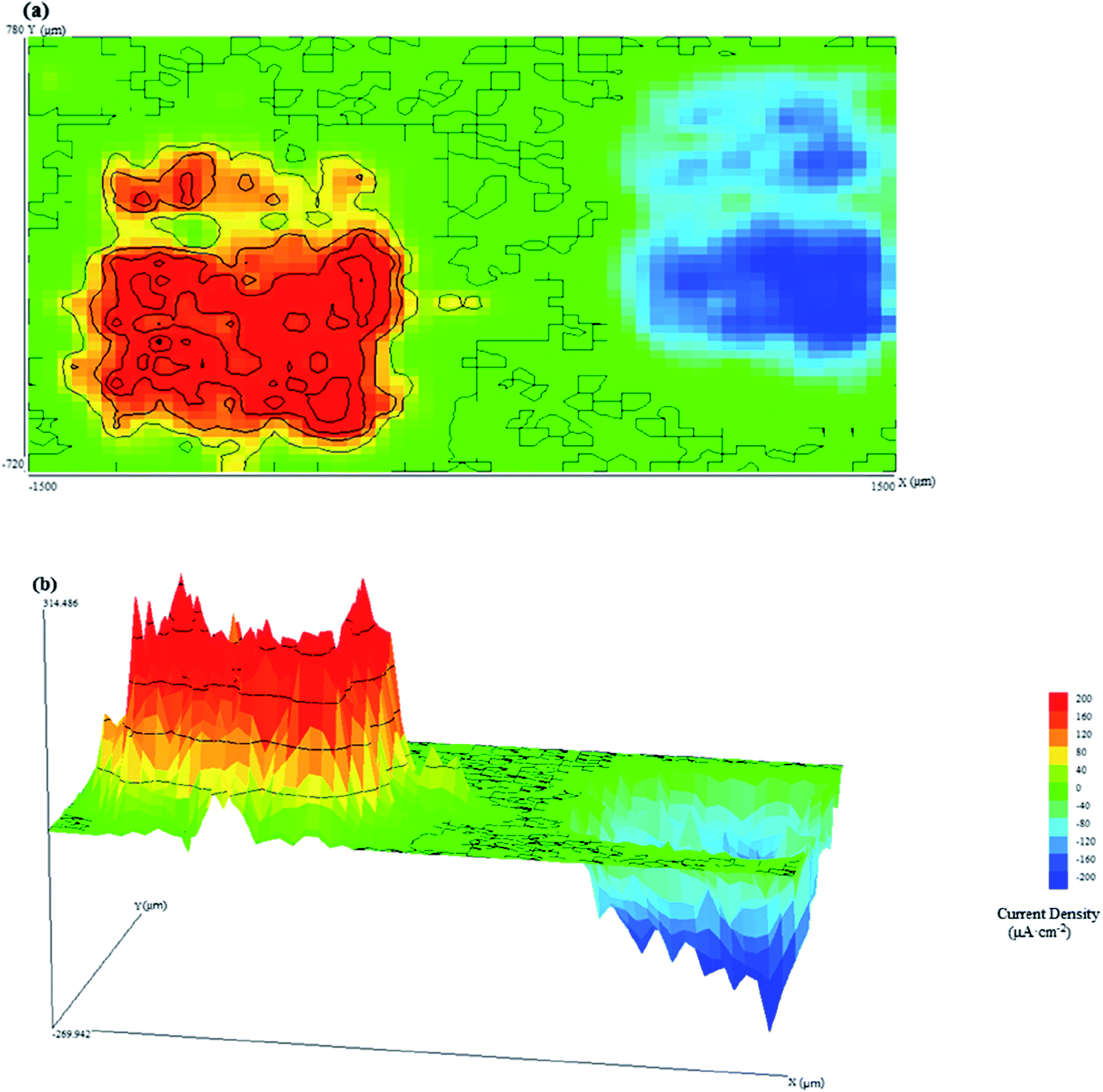 | ||
| Fig. 5 (a) Two-dimensional and (b) three-dimensional SVET current density maps of connected CR and LC samples at pH = 11.3. | ||
It can be seen from Fig. 5 that when galvanic corrosion occurred on LC and CR, LC served as the anode and CR as the cathode. The current density of CR and LC were both approximately 200 μA cm−2. However, the current distributions at the anodic and cathodic regions were different. The current density of the anodic region was greater than that of the cathodic region.
The above analysis shows that when the pH is 9.0 or 11.3, galvanic corrosion occurs when CR and LC are coupled. Additionally, at high pH, a small current is used to maintain electrochemical corrosion process when the anode and cathode are in alkaline media. Because LC exhibited a high, broadly distributed current density due to its high surface activity, it was considered to have uniform corrosion, although some pitting corrosion may have occurred. In contrast, CR was protected from the galvanic corrosion, and only high and sharp cathodic current peaks were observed, which indicated the existence of pitting corrosion from chloride ions. Additionally, the current density was smaller when the pH was 11.3 compared to that when the pH was 9.0 due to several factors. First, the high pH decreased the potential difference between CR and LC, decreasing the driving force of the galvanic corrosion. Second, when the chloride ion concentration was 5 mol L−1, the passivation capabilities of CR and LC in the simulated concrete pore solution were improved, thus resulting in improvements in the corrosion resistances of CR and LC.22
Fig. 6 shows the SVET current density maps when CR and LC are connected at pH = 13.6, including (a) a two-dimensional map and (b) a three-dimensional map.
 | ||
| Fig. 6 (a) Two-dimensional and (b) three-dimensional SVET current density maps when CR and LC are connected at pH = 13.6. | ||
When the pH was 13.6, even though LC and CR were in contact, galvanic corrosion did not occur, leaving only regular corrosion to occur on each electrode because the difference between the potentials of CR and LC was small. As a result, the driving force was not sufficient to produce galvanic corrosion. The current density for the corrosion of LC was large, approximately 100 μA cm−2, while the current density for the corrosion of CR was small, approximately 50 μA cm−2. This is because under highly alkaline conditions, it is easier for CR to form a passivation film than for LC to do so. Furthermore, even under the corrosion of chloride ions, CR still possesses an excellent capability to repair its passivation film. Fig. 6(b) shows that there were many current density peaks on the CR and LC. Past research23 has shown that under corrosive conditions for CR and LC, pitting corrosion predominates, which explains the many sharp current density peaks in the SVET maps.
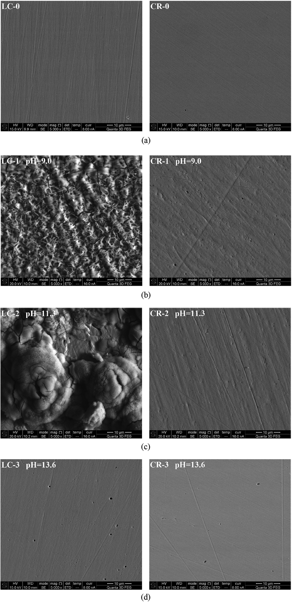 | ||
| Fig. 7 Surface morphology of corroded CR and LC: (a) LC-0 and CR-0 are the original surfaces of the LC and CR samples; (b) LC-1 and CR-1 refer to the surfaces of the LC and CR after galvanic corrosion in solution LA; (c) LC-2 and CR-2 refer to the surfaces of LC and CR after galvanic corrosion in solution MA; (d) LC-3 and CR-3 refer to the surfaces of LC and CR after galvanic corrosion in solution HA. | ||
It can be seen from Fig. 7(a) that the untested LC and CR exhibited smooth surfaces. Fig. 7(b) shows that after the galvanic corrosion of LC and CR in the simulated concrete pore solution with a pH of 9.0 and a chloride ion concentration of 5 mol L−1, the surface of LC was severely corroded, generating a large amount of corrosion products that were evenly distributed on the surface. In contrast, the surface of CR was roughened and only small pits appeared. Fig. 7(c) shows that after the galvanic corrosion of LC and CR in the simulated concrete pore solution with a pH of 11.3 and a chloride ion concentration of 5 mol L−1, the surface of LC had accumulated corrosion products and obvious corrosions pits. In contrast, the surface of CR was smooth and pits appeared only at certain locations. Fig. 7(d) shows that in the simulated concrete pore solution with a pH of 13.6 and a chloride ion concentration of 5 mol L−1, CR and LC both exhibited substantial corrosion and obvious corrosion pits on their surfaces, although the corrosion was more severe on LC than on CR. The above analysis shows that when galvanic corrosion occurs on CR and LC, the corrosion is more severe for the anode (LC) than for the protected cathode (CR). To further analyse the corrosion products from the galvanic corrosion of LC and CR, EDS was performed on LC and CR samples corroded in solutions with pH of 9.0 and 11.3.
Fig. 8 shows the EDS of CR and LC after galvanic corrosion in solutions with pH of 9.0 and 11.3.
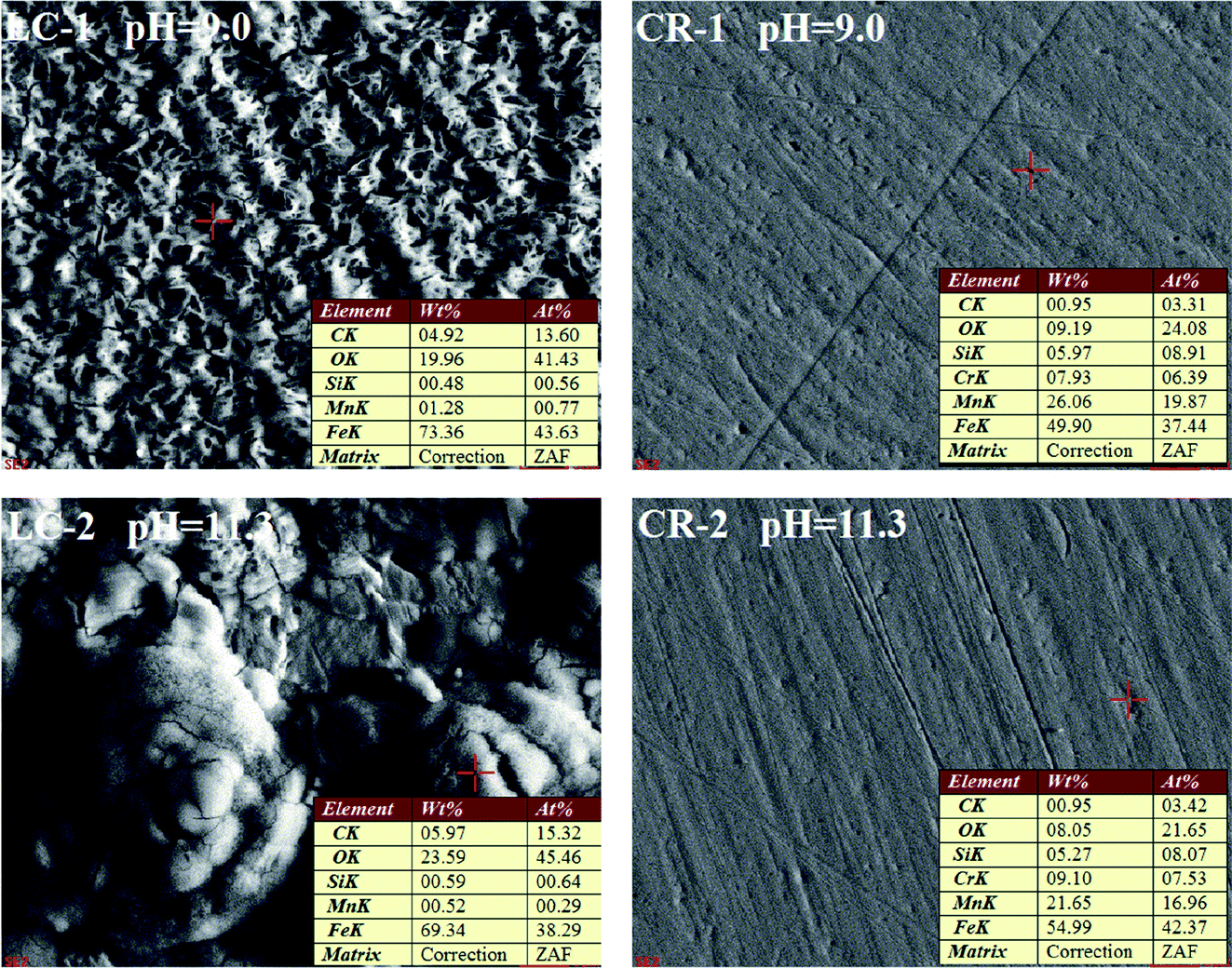 | ||
| Fig. 8 EDS of CR and LC after galvanic corrosion in solutions with pH of 9.0 and 11.3. | ||
It can be seen from Fig. 8 that the main corrosion products on the LC surface after galvanic corrosion were iron oxides. There was some corrosion on the surface of CR that occurred at positions with higher Mn content. It is hypothesized that the pitting corrosion of CR is related to the doping of Mn. Under the attack of chloride ions, corrosion first developed in the Mn inclusions in CR and further developed into corrosion pits. To better understand the surface morphology of CR, DHM was performed.
Fig. 9 shows the three-dimensional surface morphology of CR and LC after galvanic corrosion in solutions with pH of 9.0 and 11.
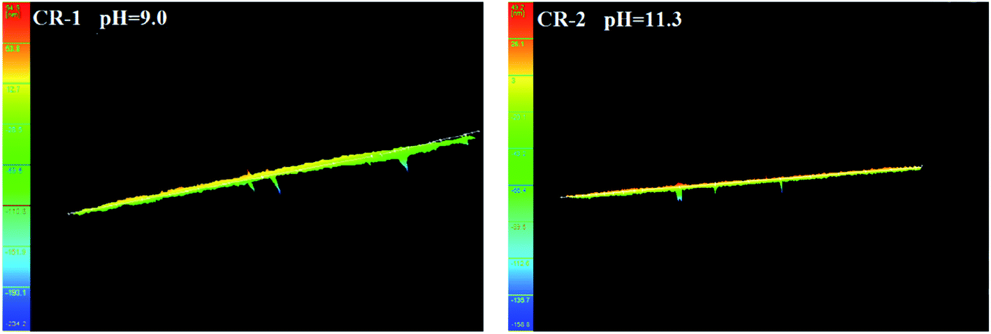 | ||
| Fig. 9 Three-dimensional surface morphology of CR and LC after galvanic corrosion in solutions with pH of 9.0 and 11. | ||
It can be seen from Fig. 9 that when the pH = 9.0, the surface of CR was roughened after galvanic corrosion, and there were pits with a nanoscale depth. When the pH = 11.3, the surface of CR was rather smooth but had pits with a nanoscale depth at certain locations.
Conclusions
In this study, OCP, SVET, SEM and reflection DHM were used to study the galvanic corrosion of novel CR and LC in simulated concrete pore solutions with different pH and 5 mol L−1 chloride ions. The following conclusions were obtained:(1) While being attacked by chloride ions, CR and LC showed corrosion behaviour that is significantly affected by the pH of the simulated concrete pore solution that they contact. With increasing pH, the potential between CR and LC decreased and the driving force for the galvanic corrosion decreased. During galvanic corrosion, LC served as the anode and CR served as the cathode.
(2) When the pH was 9.0, galvanic corrosion occurred on both CR and LC. Additionally, the corrosion rate was high. Pitting corrosion was locally developed on CR whereas uniform corrosion predominated on LC. In both cases, there was apparent accumulation of corrosion products on the surface of samples. When the pH was 11.3, galvanic corrosion occurred when CR and LC were in contact. CR had a relatively smooth surface, with only a small amount of pitting corrosion. In contrast, both pitting corrosion and uniform corrosion appeared on LC. There was apparent pitting corrosion and an accumulation of corrosion products. When the pH was 13.6, there was no galvanic corrosion when CR and LC were in contact, and pitting corrosion predominated on CR and LC.
(3) With chloride ion corrosion and low pH, the galvanic corrosion between CR and LC cannot be ignored. Therefore, galvanic corrosion occurred easily between CR and LC at regions with severe chloride ion corrosion and carbonization. Therefore, it is not recommended to put CR and LC in contact in those regions.
Conflicts of interest
There are no conflicts of interest to declare.Acknowledgements
The authors greatly acknowledge the support from 2016YFC0305100, the National Natural Science Foundation of China (No. 51438003, 51278098, 51578143, 51678144), the National Basic Research Program of China “973 Project” (No. 2015CB655105), Technological Development Projects of China Railway Engineering Corporation (2014G004-F), and the Industry-University Research Cooperative Innovation Fund of Jiangsu Province (No. BY2013091).References
- B. Sanz, J. Planas and J. M. Sancho, Cem. Concr. Res., 2017, 101, 68 CrossRef CAS.
- M. M. Mirsayar, K. Huang and G. Z. Dan, Transp. Res. Rec., 2016, 2590, 10 CrossRef.
- H. P. Seifert and S. Ritter, Corros. Sci., 2016, 108, 134 CrossRef CAS.
- R. Liu, L. Jiang, J. Xu, C. Xiong and Z. Song, Constr. Build. Mater., 2014, 56, 16 CrossRef.
- H. Binici, H. Zengin, G. Zengin and F. Yasarer, Corros. Sci., 2008, 50, 2140 CrossRef CAS.
- J. H. Jiang and Y. S. Yuan, Constr. Build. Mater., 2013, 44, 287 CrossRef.
- F. Shaheen and B. Pradhan, Cem. Concr. Res., 2017, 91, 73 CrossRef CAS.
- M. Serdar, C. Meral, M. Kunz, D. Bjegovic, H. R. Wenk and P. J. Monteiro, Cem. Concr. Res., 2015, 71, 93 CrossRef CAS.
- Z. Ai, W. Sun, J. Jiang, D. Song and H. Ma, Materials, 2016, 9, 749 CrossRef PubMed.
- J. Jiang, D. Wang, H.-y. Chu, H. Ma, Y. Liu, Y. Gao, J. Shi and W. Sun, Materials, 2017, 10, 412 CrossRef PubMed.
- J. Shi, W. Sun, J. Jiang and Y. Zhang, Constr. Build. Mater., 2016, 111, 805 CrossRef CAS.
- C. F. Dong, K. Xiao, X. G. Li and Y. F. Cheng, Wear, 2010, 270, 39 CrossRef CAS.
- H. N. Krogstad and R. Johnsen, Corros. Sci., 2017, 121, 43 CrossRef CAS.
- C. M. Abreu, M. J. Cristóbal, M. F. Montemor, X. R. Nóvoa, G. Pena and M. C. Pérez, Electrochim. Acta, 2002, 47, 2271 CrossRef CAS.
- J. Z. Ai, X. P. Guo and Z. Y. Chen, Appl. Surf. Sci., 2006, 253, 683 CrossRef CAS.
- Z. Liu, M. Curioni, P. Jamshidi, A. Walker, P. Prengnell, G. E. Thompson and P. Skeldon, Appl. Surf. Sci., 2014, 314, 233 CrossRef CAS.
- H. Zhang, X. Pang and K. Gao, Appl. Surf. Sci., 2018, 442, 446 CrossRef CAS.
- M. Saremi and E. Mahallati, Cem. Concr. Res., 2002, 32, 1915 CrossRef CAS.
- J. K. Boah, S. K. Somuah and P. Leblanc, Corrosion, 1990, 46, 153 CrossRef CAS.
- C. Alonso, C. Andrade, M. Castellote and P. Castro, Cem. Concr. Res., 2000, 30, 1047 CrossRef CAS.
- C. Alonso, M. Castellote and C. Andrade, Electrochim. Acta, 2002, 47, 3469 CrossRef CAS.
- C. Baek and J. D. Lee, Constr. Build. Mater., 2009, 23, 1902 CrossRef.
- A. Davoodi, M. Pakshir, M. Babaiee and G. R. Ebrahimi, Corros. Sci., 2011, 53, 399 CrossRef CAS.
- C. Cao, Principles of Electrochemistry of Corrosion, Chemical Industry Press, Beijing, 2004 Search PubMed.
- J. Jiang, Y. Liu, H.-y. Chu, D. Wang, H. Ma and W. Sun, Materials, 2017, 10, 903 CrossRef PubMed.
- Q. Ni, X. Xia, J. Zhang, N. Dai and Y. Fan, Electrochim. Acta, 2017, 247, 207 CrossRef CAS.
| This journal is © The Royal Society of Chemistry 2018 |