
 Open Access Article
 This Open Access Article is licensed under a Creative Commons Attribution-Non Commercial 3.0 Unported Licence
Oxidized multiwall carbon nanotube/silicone foam composites with effective electromagnetic interference shielding and high gamma radiation stability†
Furong Huanga,
Yimeng Wanga,
Peiyu Wangb,
Hui-ling Mac,
Xibang Chena,
Ke Caoc,
Yongmao Peib,
Jing Penga,
Jiuqiang Lia and
Maolin Zhai *a
*a
aBeijing National Laboratory for Molecular Sciences, Radiochemistry and Radiation Chemistry Key Laboratory of Fundamental Science, The Key Laboratory of Polymer Chemistry and Physics of the Ministry of Education, College of Chemistry and Molecular Engineering, Peking University, Beijing 100871, China. E-mail: mlzhai@pku.edu.cn
bState Key Laboratory for Turbulence and Complex Systems, College of Engineering, Peking University, Beijing 100871, China
cBeijing Key Laboratory of Radiation Advanced Materials, Beijing Research Center for Radiation Application, Beijing 100015, China
First published on 4th July 2018
Abstract
Oxidized multiwall carbon nanotubes (o-MWCNTs) were introduced into silicone foam to fabricate an electromagnetic interference (EMI) shielding material with high gamma radiation stability by solution casting followed by foaming and cross-linking reactions. The as-prepared o-MWCNT/silicone foam composites exhibited excellent mechanical strength and effective EMI shielding properties with superior EMI shielding effectiveness (SE) ranging from 26 to 73 dB at a 0.5–6.4 mm thickness with 30 wt% o-MWCNTs in the Ku band. Moreover, the composites have good gamma radiation stability, showing relatively stable EMI shielding properties and an improvement of hardness and pressure resistance after gamma irradiation with the absorbed dose of 500 kGy. These results indicate that the o-MWCNT/silicone foam composite is an attractive candidate for EMI shielding in some ionizing radiation environments.
Introduction
With the rapid development of communication technology, electromagnetic waves as the information propagation carriers, are widely applied in many areas, such as communication tools, antenna systems, scientific electronic instruments, remote sensors, space-exploration devices and military equipment.1 However, the electromagnetic waves generated from these electronic devices will cause electromagnetic radiation pollution, which may degrade the performance of devices and lead to the damage of information security.2,3 It is effective to use EMI shielding materials to prevent the propagation of electromagnetic waves and reduce the pollution of electromagnetic radiation. Traditional shielding materials are metals and alloys, which suffer from poor chemical resistance, heavy weights, poor flexibility and difficulty in processing.4Recently, conductive polymer composites (CPCs) as EMI shielding materials have attracted broad attention due to their light weight, ease of fabrication, good stability and low cost.5,6 Solution casting is a common dispersion technique for the preparation of CPC EMI shielding materials because of the well dispersion of conductive fillers in polymer matrices and the prevention of damage to fillers.7 Multiwall carbon nanotubes (MWCNTs), possessing a very high aspect ratio and extraordinary conductivity, are widely used as conductive fillers in polymers and applied to EMI shielding.8 M. H. Al-Saleh et al. compared the EMI SE of acrylonitrile-butadiene-styrene (ABS) with three different carbon nanofillers, finding that MWCNTs exhibited the highest EMI SE.9 However, the poor dispersion of MWCNTs caused by their entanglement and lack of interfacial compatibility with polymers, will give rise to damage in the EMI shielding performance of polymer composites. It has been reported that the oxidation of MWCNTs could introduce functional groups such as carboxylic and carbonyl groups on their surface, which could form hydrogen bonding interactions with polymer and lead to a better dispersion of o-MWCNTs in polymer matrices.10,11 Therefore, the polymers filled with o-MWCNTs may exhibited better EMI shielding performance.
Furthermore, EMI shielding materials are widely used in satellite communications and military applications such as weapon-locating radar. Consequently, the gamma rays generated from the space and nuclear radiation environment, would not only decrease the EMI shielding performance of shielding materials, but also destroy the mechanical structures of polymer matrix.12 Thus, it is crucial to fabricate an EMI shielding material with high ionizing radiation stability. Silicone rubber foam, consisting of Si–O bonds in the main chain, has advantages over other polymers including great resistance to damage from extreme temperature, radiation, weather and chemicals.13 The foam structure provides the silicone rubber with low density as well as shock and impact resistance. According to the literatures, the introduction of foam structure can further increase the SE by enhancing the multiple reflections of electromagnetic waves.14–16 Therefore, o-MWCNT/silicone foam composites are hopeful to be used in the space and nuclear radiation environment as shielding materials. In addition, the ionizing radiation stability of shielding materials should be examined. However, few studies have been reported on the effect of ionizing radiation on shielding materials to the best of our knowledge.
In this study, functionalized MWCNTs were used to produce o-MWCNT/silicone foam composites by solution casting followed by foaming and cross-linking reactions. O-MWCNT/silicone foam composites with wide ranges of o-MWCNT content from 1 to 30 wt% and thicknesses from 0.5 to 6.5 mm were prepared successfully. The EMI shielding, dielectric and mechanical properties of the composites were systematically investigated. Moreover, the effect of gamma radiation on o-MWCNT/silicone foam composites was evaluated with the absorbed dose from 100 to 500 kGy.
Experimental
Materials
MWCNTs were purchased from Shenzhen Nanotech Port Co. Ltd, synthesized by catalytic CVD process. Their specifications are as follows: purity, >95%; outer diameter, 20–40 nm; length, 5–15 μm; specific surface area, 40–300 m2 g−1; tap density, 0.15–0.28 g cm−3; ash, ≤0.2 wt%; amorphous carbon, <3%.The 65% nitric acid of guaranteed grade and 95% sulfuric acid of analytical grade were obtained from Xilong Scientific Co Ltd. Tetrahydrofuran (THF) of analytical grade was obtained from the Beijing Chemical Works.
Silicone foam reactants were kindly supplied by Bluestar Silicones as a two-part system (Rhodorsil RT Foam 3240).
Preparation of o-MWCNT/silicone foam composites
The detailed oxidation process of MWCNTs is given in ESI.† Solution casting method was used to prepare the silicone foam with different content of o-MWCNTs. O-MWCNTs were dispersed in THF under magnetic stirring and subjected to probe sonication by a Y99-2 DN ultrasonicator (Ningbo, China) for 1 h. 1 g of part A component was added to the o-MWCNT/THF and left stirring overnight. After THF was evaporated at 40 °C until constant weight was achieved, 1 g of part B component was thoroughly mixed with the o-MWCNT/part A mixture. The final sample was poured into a rectangular mould and foaming took place at room temperature. Silicone foams containing 1, 5, 10, 20 and 30 wt% o-MWCNTs were prepared.Gamma radiation effect of o-MWCNT/silicone foam composites
The silicone foam composites were sealed in the glass tube and directly irradiated using γ-rays from a 60Co source at the Department of Applied Chemistry of Peking University with the absorbed doses from 100 to 500 kilogray (kGy) at ambient temperature.Characterization of o-MWCNT/silicone foam composites
EMI SE was characterized using an Agilent E8363C Phasor Network Analyzer (PNA) in the 12.4–18 GHz (Ku-band) range, which is applied to satellite communications and military applications. The dimensions of the sample holder taken for shielding measurements were as follows: length, 15.72 mm, width, 7.82 mm and thickness, 6.48 mm. The samples were measured in triplicate to get an average. The scattering parameters (S parameters) (S11, S12, S21 and S22) were recorded over the Ku-band frequency range. Then the total SE (SET), shielding by reflection (SER) and absorption (SEA) were calculated by eqn (1)–(3) based on the S parameters.
 | (1) |
 | (2) |
 | (3) |
Scanning electron microscopy (SEM) analysis was performed at an accelerating voltage of 2 kV on a Hitachi S-4800 field emission scanning electron microscopy (FESEM). The compressive strength of the samples was tested by universal material testing instrument (Instron 3365). Silicone foam cylinders with the size of Φ10.5 × 2.5 mm were prepared. The compressive test was conducted with a constant strain rate of 1 mm min−1 until 80% reduction in specimen height. The samples were measured in triplicate to get an average. Compressive modulus was calculated as the slope of the initial linear potion of the curve. The thermal analysis (TA) was recorded with a Q600-SDT instrument (TA Instruments, America) in the nitrogen gas atmosphere, over a temperature range of 30–800 °C with a heating rate of 10 °C min−1. X-ray photoelectron spectroscopy (XPS) spectra were recorded on an AXIS-Ultra Imaging Photoelectron Spectrometer from Kratos Analytical Ltd., which used monochromatic Al-Kα radiation under a vacuum of 2 × 10⁻⁸ Pa.
Results and discussion
Synthesis and characterization of silicone foam and o-MWCNTs
Silicone foam is prepared by foaming and cross-linking reactions, which occur simultaneously. The foaming reaction between Si–H and Si–OH groups and cross-linking reaction between the vinyl end blocked groups and Si–H groups take place in the presence of platinum (Pt) catalyst with the generation of hydrogen gas.The surface area of pristine MWCNTs is so large that strong attractive forces existed between the MWCNTs, which undesirably induces the agglomeration and entanglement of MWCNTs. Besides, the pristine MWCNTs are lack of interfacial adhesion with polymer materials. In order to improve the compatibility between MWCNTs and silicone foam matrix, MWCNTs were oxidized by refluxing with a mixture of HNO3/H2SO4. The o-MWCNTs were dispersed more uniformly than MWCNTs in THF, as shown in Fig. S1.† The oxidative treatment of MWCNTs led to an increase in the atomic oxygen percentage from 1.59% to 9.32%, which was confirmed by XPS (Fig. S2a and c†). According to XPS C 1s spectra (Fig. S2b and d†), the amount of COOH and sp3 C–C increased, while C–OH decreased after the oxidation reaction, which further demonstrated the oxidation of MWCNTs. From Fig. S3,† we can see that o-MWCNTs exhibited a weight loss of 13.7%, which was attributed to the decarboxylation of carboxyl groups and the elimination of hydroxyl groups present on the MWCNT walls. These oxygen-containing groups of o-MWCNTs could form hydrogen bonding with Si–OH groups in silicone foam, so the interfacial adhesion between the o-MWCNTs and silicone foam would be enhanced.
EMI SE analysis
EMI SE quantitatively describes the EMI shielding ability of the materials.17 The EMI SE is significantly influenced by the dispersion of filler in the polymer matrix.18 For comparison, the EMI SE of the pristine MWCNT/silicone foam and o-MWCNT/silicone foam composites were measured, as shown in the Fig. 1a. The o-MWCNT/silicone foam composite displayed a better EMI SE than the pristine MWCNT/silicone foam composite. It is attributed to that o-MWCNTs could interact with Si–OH groups of silicone foam to form hydrogen bonding, which improves the dispersion of o-MWCNTs and leads to the formation of more interconnected conductive networks in the silicone foam. In addition, the dispersed solvent not only affects the dispersion of o-MWCNTs, but also influences the solubility of part A for forming silicone foam. From Fig. 1b, the composite prepared by using THF as the dispersed solvent presented the best EMI shielding performance. It is speculated that THF is an ideal solvent for homogeneous dispersion of o-MWCNTs in the silicone foam. Hence, o-MWCNTs were chosen as the fillers and THF was used as the dispersed solvent to prepare o-MWCNT/silicone foam composites in the subsequent experiments.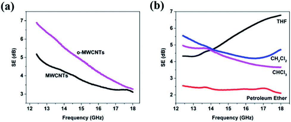 | ||
| Fig. 1 EMI SE of: (a) the pristine MWCNT/silicone foam and o-MWCNT/silicone foam composites using THF as dispersed solvent. (b) o-MWCNT/silicone foam composites with various dispersed solvent. The filler content of the composites is 5 wt%. | ||
The o-MWCNT/silicone foam mixture was stirred vigorously and poured into designed mould followed by foaming process to get uniformly dispersed composites with various shapes. The optical images of composites with various o-MWCNT content are shown in Fig. 2a–c. The composites exhibited porous architectures with excellent flexibility. The dispersion of o-MWCNTs in the silicone foam matrix was confirmed by SEM images. Fig. 2d shows a cellular structure with interconnected micro-open pores of pure silicone foam, whose surface is quite flat seen in the magnified SEM image. With the increasing o-MWCNT content from 1 to 30 wt%, the amount of o-MWCNTs in the silicone foam increased, as shown in Fig. 2e–i. O-MWCNTs dispersed uniformly in the silicone foam and no agglomeration of o-MWCNTs was observed even at the high o-MWCNT content because of the interfacial interactions between the o-MWCNTs and silicone foam. The interfacial interactions may primarily derive from two aspects: (1) the oxygen functional groups presented on the MWCNT walls could form hydrogen bonding interactions with silicone foam; (2) the π-system in the o-MWCNTs could form π–CH interactions with side chains of silicone foam.19 These interactions not only lead to the homogeneous dispersion of o-MWCNTs in the silicone foam, but also prevent the aggregation of o-MWCNTs which is beneficial to the formation of o-MWCNT conductive network.
 | ||
| Fig. 2 Optical images of o-MWCNT/silicone foam composites with various o-MWCNT content: (a) (up to down) 1, 5 and 10 wt%; (b) 1 wt%; (c) (left to right) 1, 5, 10, 20 and 30 wt%. SEM images: (d) silicone foam without o-MWCNTs; (e–i): o-MWCNT/silicone foam composites with various o-MWCNT content: 1, 5, 10, 20, 30 wt%. | ||
According to the transmission line theory, the attenuation of electromagnetic waves occurs by three mechanisms: reflection, absorption and multiple reflections, so the SET is the sum of all the three terms. If the distance between the reflecting surfaces or interfaces is considerably larger than the skin depth, the contribution from multiple reflections is merged in the absorption.20 Therefore, the SET has the following expression:
| SET (dB) = SER + SEA | (4) |
Fig. 3a shows the EMI SE of o-MWCNT/silicone foam composites with various o-MWCNT content as a function of frequency. At the same content of o-MWCNT, the SET of the composites is almost independent of frequency in the measured bands, which is consistent with other types of polymer composites such as MWNTs/PS/PMMA,21 MWCNT/PU22 and PS/MWCNT/Graphite Nanoplate Nanocomposites.23 As shown in Fig. 3b, the effect of o-MWCNT content on SEA, SER and SET was studied at the frequency of 12.4 GHz. With the increasing o-MWCNT content from 1 to 30 wt%, both SET and SEA increased while SER remained unchanged. For example, the average values of SET, SEA and SER of o-MWCNT/silicone foam composites with 30 wt% o-MWCNTs were 40.2, 33.3 and 6.9 dB, respectively, indicating the contribution of absorption (82.8%) was much larger than that of reflection (17.2%) at high o-MWCNT content as shown in Fig. 3c. It is noteworthy that the maximum SET can reach 47 dB with 30 wt% of o-MWCNTs, which is comparable or even superior to the reported polymers with the similar content of fillers. For instance, the SET of rGO/PS,24 rGO/Fe3O4/PVA25 and MWCNTs/PMMA26 is 29, 15 and 27 dB, respectively, as listed in the Table 1 that compares the EMI SE of various polymer composites reported in the literature.
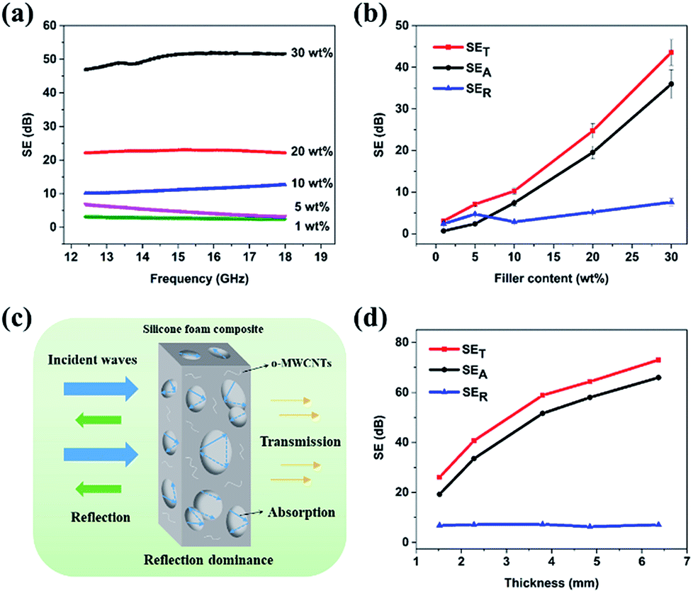 | ||
| Fig. 3 (a) SE of o-MWCNT/silicone foam composites with various o-MWCNT content. (b) SEA, SER and SET at 12.4 GHz of o-MWCNT/silicone foam composites as a function of o-MWCNT content. (c) Schematic representation of EMI shielding mechanism for o-MWCNT/silicone foam composite. (d) SEA, SER and SET at 12.4 GHz of o-MWCNT/silicone foam composites as a function of thickness. The thickness of the samples in (a) and (b) is around 2.5 mm; error bars represent the standard deviation. | ||
| Fillera | Filler [wt%] | Thickness [mm] | Polymerb | EMI SE [dB] | Ref. |
|---|---|---|---|---|---|
| a SWCNT, single wall carbon nanotube; CNF, carbon nanofiber; rGO, reduced graphene oxide.b PMMA, poly(methylmethacrylate); WPU, water-borne polyurethane; PVDF, poly(vinylidene fluoride); PEDOT, poly(3,4-ethylenedioxythiophene); PU, polyurethane; PS, polystyrene; PEI, polyetherimide; PANI, polyaniline; PVA, polyvinyl alcohol; PVC, polyvinyl chloride; SA, sodium alginate. | |||||
| o-MWCNTs | 30 | 2.5 | Silicone foam | 40 | This work |
| MWCNTs | 40 | 0.165 | PMMA | 27 | 26 |
| MWCNTs | 76 | 4.5 | WPU | 50 | 5 |
| MWCNTs | 15 | 2.0 | PVDF | 57 | 27 |
| MWCNTs | 15 | 2.8 | PEDOT | 58 | 28 |
| SWCNT | 15 | 2 | Epoxy | 25 | 29 |
| SWCNT | 20 | 2 | PU | 18 | 30 |
| CNT | 7 | — | PS foam | 19 | 31 |
| CNF | 15 | — | PS foam | 19 | 32 |
| rGO | 30 | 2.5 | PS foam | 29 | 24 |
| rGO | 10 | 2.3 | PEI | 22 | 15 |
| rGO | 20 | 2.0 | Wax | 29 | 33 |
| rGO/γ-Fe2O3 | 75 | 2.5 | PANI | 51 | 34 |
| rGO/Fe3O4 | 35 | 0.3 | PVA | 15 | 25 |
| rGO/Fe3O4 | 10 | 1.8 | PVC | 13 | 35 |
| rGO/Fe3O4 | 10 | 2.5 | PEI foam | 18 | 36 |
| Ag nanowires | 14 | 0.013 | PANI | 50 | 37 |
| Ti3C2Tx | 90 | 0.008 | SA | 57 | 2 |
It is well known that the EMI SE is not only dependent on the dispersion and content of the fillers, but also dependent on the thickness of the polymer composites. Fig. 3d reveals the influence of sample thickness on the EMI SE at 30 wt% o-MWCNT loading. By increasing the sample thickness from 0.5 to 6.4 mm, the SET of o-MWCNT/silicone foam composites increased from 26 to 73 dB, which is high enough to meet the requirements for commercial applications and even the military applications.38 We can also see that SEA increased with the increasing sample thickness, whereas SER was almost unchanged. According to shielding theory, SEA and SER could be expressed as:
 | (5) |
 | (6) |
In order to determine the shielding mechanism of o-MWCNT/silicone foam composites, the reflection (R), transmission (T) and absorption (A) coefficients were calculated based on the S parameters. According to Fig. S4a,† R coefficients were increased with growing filler content, which is mainly attributed to the enhanced electrical conductivity.17 The R coefficients are higher than A coefficients with various filler content, suggesting a reflection-dominant shielding mechanism. Additionally, the R, T and A coefficients slightly changed with the thickness of different samples.
The dielectric characteristics of o-MWCNT/silicone foam composites are given in Fig. S5.† There are increases of complex permittivity (Fig. S5a and b†), dielectric tangent loss (Fig. S5c†) and AC conductivity (Fig. S5d†) with increasing o-MWCNT content, suggesting that more o-MWCNT conductive networks were formed. The increase of conductive networks, which act as dissipating mobile charge carriers, results in higher dielectric tangent loss and consequently higher attenuation of electromagnetic waves.
Compression performance
As is well-known, silicone foam possesses excellent mechanical properties, which makes them promising polymer for various practical applications. The compressive stress–strain curves of silicone foam can be divided into the elastic region, yielding region and densification region, while there is no clear boundary between the elastic region and yielding region. As shown in Fig. 4a, there was no obvious breakage observed in the curves before the stress of 6 MPa, indicating the superior mechanical property of silicone foam composites. The corresponding stress at the same strain of silicone foam composites increased with the increasing o-MWCNT content while the range of yielding region decreased. It demonstrated that the silicone foam composites with higher o-MWCNT content exhibited higher strength and hardness, by contrast, the silicone foam composites with lower o-MWCNT content behaved more flexible. From Fig. 4b, the 5 wt% o-MWCNT/silicone foam showed a compressive stress of 86.4 MPa at the strain of 86% without being broken. The o-MWCNT/silicone foam composites showed higher compressive strengths (several tens of MPa) than the porous MWCNT/WPU composites (several tens to hundreds of kPa), which demonstrated that o-MWCNT/silicone foam composites were strong and robust.5 When the o-MWCNT content increased from 1 to 30 wt%, the compressive modulus of o-MWCNT/silicone foam increased by nearly 15 times from 0.8 to 11.9 MPa (Fig. 4c).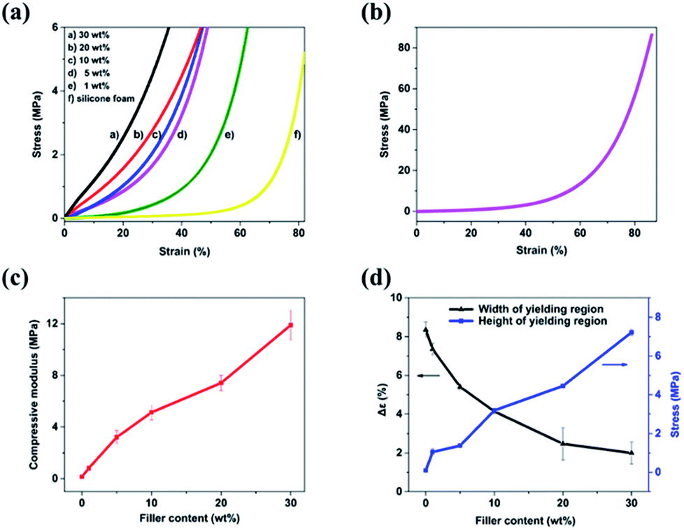 | ||
| Fig. 4 (a) Compressive stress–strain curves of silicone foam. (b) Compressive stress–strain curve of 5 wt% o-MWCNT/silicone foam composite. (c) Compressive modulus and (d) the width (Δε) and the height (σε=0.40) of yielding region of o-MWCNT/silicone foam composites with various o-MWCNT content. | ||
The energy is absorbed through the deformation of silicone foam in the yielding region. The width and the height of yielding region are employed to quantitatively evaluate the compression performance of the silicone foam. The width of yielding region is the difference of strain in the stress of 400 and 200 kPa, representing the damping effect of materials. The height of yielding region is defined as the stress at the strain of 40%, relating to the hardness and pressure resistance of materials.
The increasing content of o-MWCNTs led to a decrease in the width of yielding region (shown in Fig. 4d), which signified the reduction of the damping effect of o-MWCNT/silicone foam composites. It is mainly because the o-MWCNTs contained in the silicone foam may affect the foaming process and decrease the porosity of silicone foam. By contrast, the higher content of o-MWCNTs raised the height of yielding region (shown in Fig. 4d). Thus, the hardness and pressure resistance of silicone foam can be further enhanced by introducing o-MWCNTs, which attributed to the hydrogen bonding interactions between the o-MWCNTs and siloxane chains.
Gamma radiation resistance
O-MWCNT/silicone foam composites were irradiated by γ-rays from a 60Co source with various absorbed doses in order to investigate their gamma radiation stability. As shown in Fig. 5a, the EMI SE of composites was almost unchanged at low loading of o-MWCNTs while decreased slightly at the content of 20 and 30 wt% with the increasing absorbed doses from 100 to 500 kGy. The SE of 30 wt% o-MWCNT/silicone foam composites irradiated at 500 kGy can reach 32 dB, which still meets the requirements for applications. According to the literature, the gamma radiation induces the structural transformation of o-MWCNTs from the graphite structure to amorphous structure at high absorbed doses due to the increase of sp3 bonds and oxygen compositions.42 Thus, it is speculated that the destruction of o-MWCNT conductive network led to the reduction of SE. Nevertheless, the decline of SE was not remarkable, suggesting a stable EMI shielding property of o-MWCNT/silicone foam composites when exposed to gamma radiation.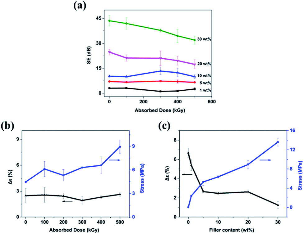 | ||
| Fig. 5 (a) SET of o-MWCNT/silicone foam composites as a function of absorbed doses with various o-MWCNT content. (b) The width and the height of yielding region of 20 wt% o-MWCNT/silicone foam composites as a function of absorbed doses. (c) The width and the height of yielding region of o-MWCNT/silicone foam composites irradiated at 500 kGy with various o-MWCNT content. | ||
The influence of gamma radiation with different absorbed doses on the mechanical properties is shown in Fig. 5b. The width of yielding region of 20 wt% o-MWCNT/silicone foam composite was nearly unchanged at the absorbed doses from 100 to 500 kGy. The absorbed doses had little influence on the damping effect of o-MWCNT/silicone foam composites, suggesting that the foam structure was not damaged by gamma radiation. In addition, the heights of yielding region increased with the increasing absorbed doses. The free radicals formed by gamma radiation could induce and improve the crosslinking of polymers, thus improving the hardness and pressure resistance of silicone foam composites.43,44 The silicone foam composites with various o-MWCNT content were irradiated at 500 kGy and the mechanical behaviors are shown in Fig. 5c. The width and the height of 30 wt% o-MWCNT/silicone foam composite were 1.25% and 13.6 MPa after irradiated at 500 kGy, by comparison, 1.99% and 7.2 MPa were obtained without gamma radiation. The irradiated silicone foam composites exhibited a good mechanical property and a stable EMI shielding property, illustrating a high gamma radiation stability.
Conclusions
O-MWCNT/silicone foam composites with various o-MWCNT content were manufactured by solvent casting followed by foaming and cross-linking reactions. The as-prepared composites exhibited superior EMI shielding performance and excellent mechanical properties due to the uniform dispersion of o-MWCNTs in silicone foam. After irradiated by gamma rays, o-MWCNT/silicone foam composites showed a relatively stable EMI shielding property and an improvement of the hardness and pressure resistance. The o-MWCNT/silicone foam composites with high resistance to gamma radiation are promising candidates for EMI shielding in space and nuclear radiation environment.Conflicts of interest
There are no conflicts to declare.Acknowledgements
This work was supported by the Science Challenge Project (No. TZ2018004) and National Natural Science Foundation of China (Project No. 11575009, 11505011, 11375019).Notes and references
- S. Biswas, S. S. Panja and S. Bose, J. Mater. Chem. C, 2018, 6, 3120–3142 RSC.
- F. Shahzad, M. Alhabeb, C. B. Hatter, B. Anasori, S. M. Hong, C. M. Koo and Y. Gogotsi, Science, 2016, 353, 1137–1140 CrossRef PubMed.
- Y. Wang, L.-j. Ni, F. Yang, F.-q. Gu, K. Liang, K. Marcus, Y.-d. Wan, J.-j. Chen and Z.-s. Feng, J. Mater. Chem. C, 2017, 5, 12769–12776 RSC.
- R. Na, J. Liu, G. Wang and S. Zhang, RSC Adv., 2018, 8, 3296–3303 RSC.
- Z. Zeng, H. Jin, M. Chen, W. Li, L. Zhou and Z. Zhang, Adv. Funct. Mater., 2016, 26, 303–310 CrossRef.
- L. Xu, L.-C. Jia, D.-X. Yan, P.-G. Ren, J.-Z. Xu and Z.-M. Li, RSC Adv., 2018, 8, 8849–8855 RSC.
- T. K. Gupta, B. P. Singh, S. R. Dhakate, V. N. Singh and R. B. Mathur, J. Mater. Chem. A, 2013, 1, 9138–9149 RSC.
- M. F. L. D. Volder, S. H. Tawfick, R. H. Baughman and A. J. Hart, Science, 2013, 339, 535–539 CrossRef PubMed.
- M. H. Al-Saleh, W. H. Saadeh and U. Sundararaj, Carbon, 2013, 60, 146–156 CrossRef.
- V. Datsyuk, M. Kalyva, K. Papagelis, J. Parthenios, D. Tasis, A. Siokou, I. Kallitsis and C. Galiotis, Carbon, 2008, 46, 833–840 CrossRef.
- T. A. Saleh, Appl. Surf. Sci., 2011, 257, 7746–7751 CrossRef.
- H.-B. Chen, B. Liu, W. Huang and W.-H. Wu, Polym. Degrad. Stab., 2015, 114, 89–93 CrossRef.
- K. Cao, Y. Ao, J. Chen, J. Peng, W. Huang, J. Li and M. Zhai, J. Appl. Polym. Sci., 2017, 134, 45404 CrossRef.
- Z. Chen, C. Xu, C. Ma, W. Ren and H.-M. Cheng, Adv. Mater., 2013, 25, 1296–1300 CrossRef PubMed.
- J. Ling, W. Zhai, W. Feng, B. Shen, J. Zhang and W. Zheng, ACS Appl. Mater. Interfaces, 2013, 5, 2677–2684 CrossRef PubMed.
- B. Shen, Y. Li, W. Zhai and W. Zheng, ACS Appl. Mater. Interfaces, 2016, 8, 8050–8057 CrossRef PubMed.
- W.-L. Song, M.-S. Cao, M.-M. Lu, S. Bi, C.-Y. Wang, J. Liu, J. Yuan and L.-Z. Fan, Carbon, 2014, 66, 67–76 CrossRef.
- S. P. Pawar, D. A. Marathe, K. Pattabhi and S. Bose, J. Mater. Chem. A, 2015, 3, 656–669 RSC.
- R. Verdejo, F. Barroso-Bujans, M. A. Rodriguez-Perez, J. A. d. Saja, M. Arroyo and M. A. Lopez-Manchado, J. Mater. Chem., 2008, 18, 3933–3939 RSC.
- A. Chaudhary, R. Kumar, S. Teotia, S. K. Dhawan, S. R. Dhakate and S. Kumari, J. Mater. Chem. C, 2017, 5, 322–332 RSC.
- R. Rohini and S. Bose, ACS Appl. Mater. Interfaces, 2014, 6, 11302–11310 CrossRef PubMed.
- Z. Zeng, M. Chen, H. Jin, W. Li, X. Xue, L. Zhou, Y. Pei, H. Zhang and Z. Zhang, Carbon, 2016, 96, 768–777 CrossRef.
- S. Maiti, N. K. Shrivastava, S. Suin and B. B. Khatua, ACS Appl. Mater. Interfaces, 2013, 5, 4712–4724 CrossRef PubMed.
- D.-X. Yan, P.-G. Ren, H. Pang, Q. Fu, M.-B. Yang and Z.-M. Li, J. Mater. Chem., 2012, 22, 18772–18774 RSC.
- B. V. Rao, P. Yadav, R. Aepuru, H. S. Panda, S. Ogale and S. N. Kale, Phys. Chem. Chem. Phys., 2015, 17, 18353–18363 RSC.
- H. M. Kim, K. Kim, C. Y. Lee and J. Joo, Appl. Phys. Lett., 2004, 84, 589–591 CrossRef.
- H. Wang, K. Zheng, X. Zhang, X. Ding, Z. Zhang, C. Bao, L. Guo, L. Chen and X. Tian, Compos. Sci. Technol., 2016, 125, 22–29 CrossRef.
- M. Farukh, A. P. Singh and S. K. Dhawan, Compos. Sci. Technol., 2015, 114, 94–102 CrossRef.
- Y. Huang, N. Li, Y. Ma, F. Du, F. Li, X. He, X. Lin, H. Gao and Y. Chen, Carbon, 2007, 45, 1614–1621 CrossRef.
- Z. Liu, G. Bai, Y. Huang, Y. Ma, F. Du, F. Li, T. Guo and Y. Chen, Carbon, 2007, 45, 821–827 CrossRef.
- Y. Yang, M. C. Gupta, K. L. Dudley and R. W. Lawrence, Nano Lett., 2005, 5, 2131–2134 CrossRef PubMed.
- Y. Yang, M. C. Gupta, K. L. Dudley and R. W. Lawrence, Adv. Mater., 2005, 17, 1999–2003 CrossRef.
- B. Wen, X. X. Wang, W. Q. Cao, H. L. Shi, M. M. Lu, G. Wang, H. B. Jin, W. Z. Wang, J. Yuan and M. S. Cao, Nanoscale, 2014, 6, 5754–5761 RSC.
- A. P. Singh, M. Mishra, P. Sambyal, B. K. Gupta, B. P. Singh, A. Chandra and S. K. Dhawan, J. Mater. Chem. A, 2014, 2, 3581–3593 RSC.
- K. Yao, J. Gong, N. Tian, Y. Lin, X. Wen, Z. Jiang, H. Na and T. Tang, RSC Adv., 2015, 5, 31910–31919 RSC.
- B. Shen, W. Zhai, M. Tao, J. Ling and W. Zheng, ACS Appl. Mater. Interfaces, 2013, 5, 11383–11391 CrossRef PubMed.
- F. Fang, Y.-Q. Li, H.-M. Xiao, N. Hu and S.-Y. Fu, J. Mater. Chem. C, 2016, 4, 4193–4203 RSC.
- N. F. Colaneri and L. W. Shacklette, IEEE Trans. Instrum. Meas., 1992, 41, 291–297 CrossRef.
- M. H. Al-Saleh and U. Sundararaj, Carbon, 2009, 47, 1738–1746 CrossRef.
- J. Ma, M. Zhan and K. Wang, ACS Appl. Mater. Interfaces, 2015, 7, 563–576 CrossRef PubMed.
- T. K. Gupta, B. P. Singh, V. N. Singh, S. Teotia, A. P. Singh, I. Elizabeth, S. R. Dhakate, S. K. Dhawan and R. B. Mathur, J. Mater. Chem. A, 2014, 2, 4256–4263 RSC.
- B. Safibonab, A. Reyhani, A. N. Golikand, S. Z. Mortazavi, S. Mirershadi and M. Ghoranneviss, Appl. Surf. Sci., 2011, 258, 766–773 CrossRef.
- M. Saiyad, N. M. Devashrayee and R. K. Mewada, Composites, Part B, 2014, 57, 71–79 CrossRef.
- Y. Wang, J. Qiu, J. Peng, J. Li and M. Zhai, J. Mater. Chem. A, 2017, 5, 12393–12399 RSC.
Footnote |
| † Electronic supplementary information (ESI) available. See DOI: 10.1039/c8ra03314e |
| This journal is © The Royal Society of Chemistry 2018 |