
 Open Access Article
 This Open Access Article is licensed under a Creative Commons Attribution-Non Commercial 3.0 Unported Licence
Refractive index sensing using the metal layer in DVD-R discs
Yuan Sun,
Shaowei Sun,
Meng Wu,
Shumei Gao* and
Jianjun Cao *
*
School of Science, Jiangnan University, Wuxi 214122, China. E-mail: jianjuncao@jiangnan.edu.cn; gaosm@jiangnan.edu.cn
First published on 1st August 2018
Abstract
In recent years, grating based bio-sensors have received much attention due to their promising applications in integrated sensing devices. However, production of high quality, large scale and low cost metal gratings is still challenging. Here, we introduce an extremely simple and low cost method to fabricate metal gratings by peeling off the metal layer from a DVD-R disc. An atomic force microscope image shows that the metal layer is a high quality grating, the period and depth of which are 740 nm and 86 nm, respectively. Based on the fabricated metal grating, refractive index sensing is experimentally achieved using two configurations, where either the resonant wavelength or the modulated laser power is measured. The sensitivity of the sensor by wavelength modulation reaches as high as 637 nmRIU−1, which is comparable with or even higher than that of the existing grating coupled sensors. Our method largely reduces the cost to fabricate high quality metal gratings and will promote the development of grating based SPR sensors.
Introduction
Surface plasmon polaritons (SPPs) are electromagnetic waves that travel along a metal–dielectric interface. The resonance excitation condition of SPPs (resonant wavelength or resonant angle) is very sensitive to the refractive index of the medium on the metal surface. Slight changes of the surrounding medium will lead to a distinct shift of the resonant wavelength or angle. This property has been widely used in label-free sensing applications in environmental monitoring, biology, food safety and medical diagnostics.1–6 The refractive index sensitivity is an important parameter for refractive index sensors. In the past years, great efforts have been made to design surface plasmon resonance (SPR) sensors that have high sensitivity. For example, gold nanocrystals have index sensitivities of about 300 nmRIU−1.7 A gold grating fabricated by FIB etching has a sensitivity of 525 nmRIU−1.8 Currently, there mainly exist three types of SPR sensors, differing in the optical excitation methods of the SPPs, namely, prism, grating, and waveguide coupling.4,9–16 Recently, grating couplers have received much more attention due to their promising applications in integrated sensing devices.17–22 While, production of high quality, large scale and low cost metal gratings is still challenging.Laser interference lithography is a nanofabrication method that can be used to fabricate large-area metal gratings. The grating structure is firstly formed on a photoresist layer which is exposed to the interference fringe of two laser beams, then metals are coated on it by evaporation coating.23–25 Nanoimprint is another high efficient nanofabrication technique. Metallic corrugated structures can be prepared by direct nanoimprint-in-metal method, where a grating mold contacts the metal film to deform it into a corrugated morphology under a moderate pressure.26 By combining methods of nanoimprint and soft lithography, production of wafer-scale nanostructured patterns was also reported.27 However, these fabrication techniques still involve lasers, grating molds, complex procedures or expensive processes.
Interestingly, commercial optical discs are good candidates to prepare metal gratings. In previous reports, the polycarbonate layer in write once DVD-R discs has been used to prepare metal gratings by depositing metals on it.28,29 The fabricated metal gratings support high quality SPPs and have been used to construct bio-sensors. While, expensive metal coating equipment is still needed in the fabrication process. In this paper, we experimentally demonstrate that the metal layer in a DVD-R disc is intrinsically a high quality metal grating, which is suitable to design SPR sensors. This means that only a cheap DVD-R disc is needed to obtain metal gratings without any chemical treatment or coating procedure. Based on the metal grating layer, refractive index sensing (RIS) is experimentally achieved using two configurations, where either the resonant wavelength or the modulated laser power is measured.
Characterization of the metal grating
CD, DVD and Blu-ray are three types of Commercial optical discs. They generally consist of polycarbonate layers, data layers and metal layers. The surface microstructures of these layers are spiral gratings with typical periods of 1600 nm, 740 nm and 320 nm for CD, DVD and Blu-ray, respectively. In this paper, we choose DVD-R to prepare metal gratings for its appropriate grating period to excite SPPs in the visible. Compared with the infrared and the ultraviolet, visible signals are much easier to be detected by silicon based detectors, which are low cost and high-performance.In our experiments, a SONY brand DVD-R disc was used to prepare the metal grating. The structure of the disc is schematically drawn in Fig. 1. It consists of several layers, including the label or printable surface, polycarbonate substrate, metal reflective layer, organic dye, polycarbonate substrate and readout surface. The surfaces of the polycarbonate substrate and also the metal layer are spiral gratings that are fabricated by the manufacturer. To isolate the metal layer, we first cut the DVD-R disc into slices by scissors along the red dashed lines in Fig. 1. And then we split the disc into two sides at the interface between the metal layer and the organic dye layer, as shown in Fig. 1. These two layers are glued together and it is easy to separate them. At last, the side with metal layer was washed with isopropanol to remove the residual dye. After the above steps, we successfully prepared the metal grating, the image of which is shown in Fig. 2(a).
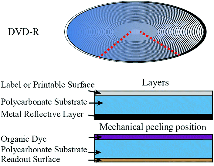 | ||
| Fig. 1 Schematic showing the structure of a DVD-R disc. | ||
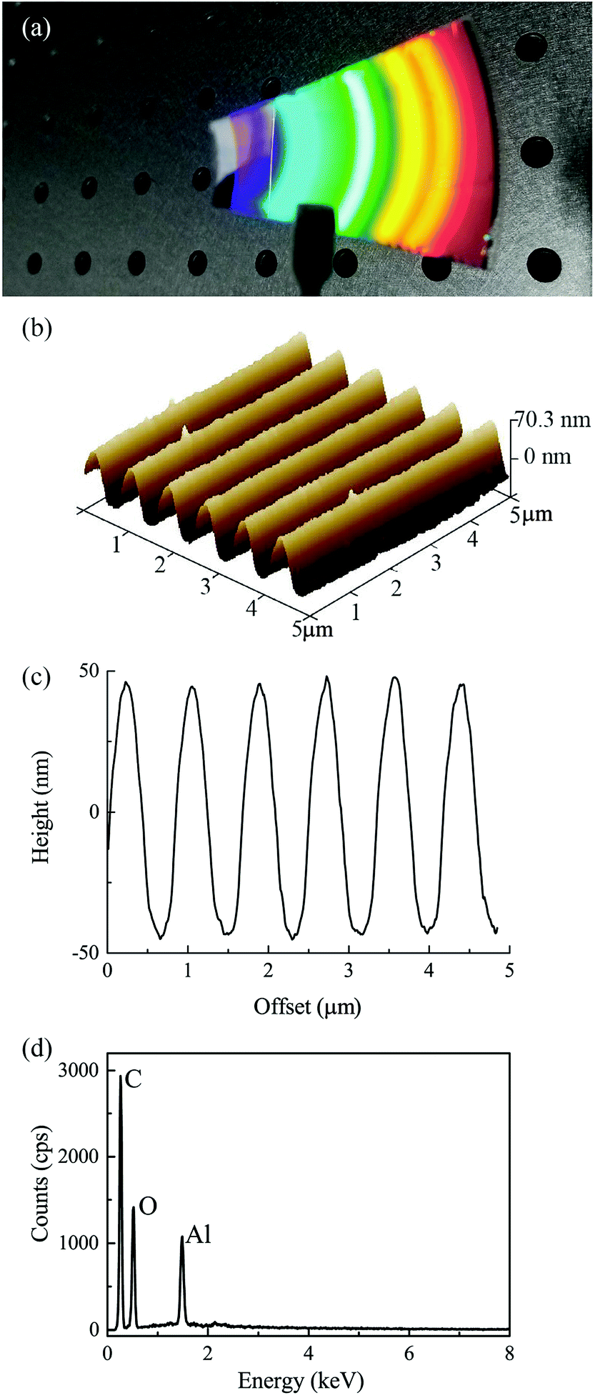 | ||
| Fig. 2 (a) Image of the metal grating peeled off from a DVD-R. (b) AFM image shows the surface morphology of the metal grating. (c) 2D profile of the corrugation. (d) The EDX spectrum of the sample. | ||
An atomic force microscope (AFM) was used to characterize the surface topography of the metal grating. The AFM image and the 2D profile are shown in Fig. 2(b) and (c), which show a grating with a period of 740 nm and a peak-to-valley modulation depth of 86 nm. The fabricated metal grating has a smooth sinusoidal profile. This profile guarantees the generation of sharp and deep plasmon resonant peaks.
We measured the Energy-dispersive X-ray (EDX) spectrum of our sample to analyze its composition. In our experiments, the metal layer is adhere to the polycarbonate substrate very tightly. It is hard to separate them. So we measured the EDX spectrum of the sample that contained both the metal layer and the polycarbonate layer. The EDX spectrum are shown in Fig. 2(d), which have three major peeks corresponding to carbon (C), oxygen (O) and aluminum (Al). Therefore, the material of the metal layer here is Al. We also measured DVD-R discs purchased from other companies, namely UNIS and RITEK. The periods of the gratings are 737 nm and 735 nm, respectively. The modulation depths are 106 nm and 91 nm, respectively. As can be seen, the structural parameters of DVD-R discs produced by different manufacturers are very close.
RIS by wavelength modulation
The metal grating prepared by our method can be used to construct various plasmonic devices. Here we experimentally demonstrate RIS by measuring the resonant wavelength shift resulted from the refractive index change. Fig. 3 shows the schematic of the setup, where the reflection spectra of the metal grating irradiated with oblique incident white light were recorded. The white light source was a deuterium halogen combo light source. Firstly, the white light was collimated by an achromat lens. Then it transmitted through a Glan–Taylor polarizer to select the TM polarization (electric vector being perpendicular to the grating direction). An aperture diaphragm was added after the polarizer to adjust the spot size illuminated on the metal grating. The metal grating was fixed on the inner surface of a cuvette, where the test liquids were added. The angle between the incident light beam and the cuvette surface normal direction was set to 30 degrees. Finally, the reflected light were directed into a fiber optic spectrometer to record the reflection spectra.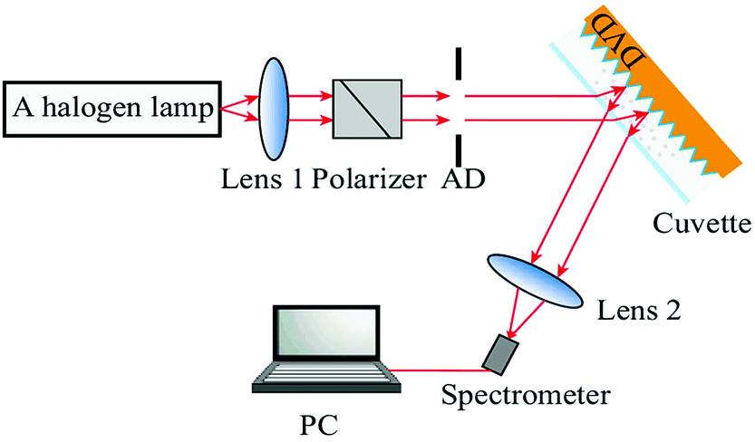 | ||
| Fig. 3 Schematic of the setup to demonstrate RIS by wavelength modulation. “AD” is an aperture diaphragm. | ||
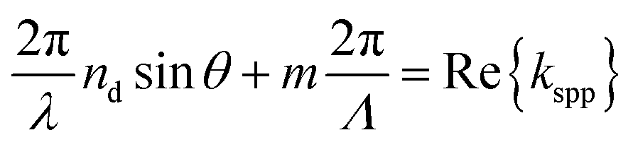
Theoretically, for surface plasmons propagating at a flat interface between two semi-infinite media, the SPP wave vector can be expressed by
 | (1) |
 | (2) |
According to the above equation, the resonant wavelength is dependent on the incident angle. By fixing the refractive index to be 1.333, the dependence of resonant wavelength on the incident angle is calculated. The results are shown in Fig. 4. It should be noted here that the value of the angle in Fig. 4 is measured in air. In our experiments, this angle is set to be 30 degrees, which corresponds to a resonant wavelength of 664 nm. The reason for us to choose 30 degrees as the excitation angle is that at this angle the resonant wavelength is in the visible wavelength range, where our light source and detector have the best performance and the refractive index sensitivity is high.
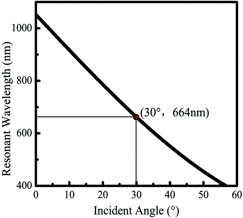 | ||
| Fig. 4 The dependence of the resonant wavelength on the incident angle (n = 1.333). | ||
To demonstrate the RIS ability of this setup, we measured the reflection spectra of various liquids, including glucose solutions with concentrations of 5%, 10%, 15% and 20% (n = 1.3402, 1.3477, 1.355 and 1.3635, respectively), deionized (DI) water (n = 1.333), methanol (n = 1.3290), ethanol (95%, n = 1.3639) and isopropyl alcohol (n = 1.3776). The results are shown in Fig. 5, where well pronounced dips are observed. The appearance of dips is an evidence for efficient excitation of surface plasmons on the dielectric–metal interface. The position of the dips corresponds to the resonant wavelength.
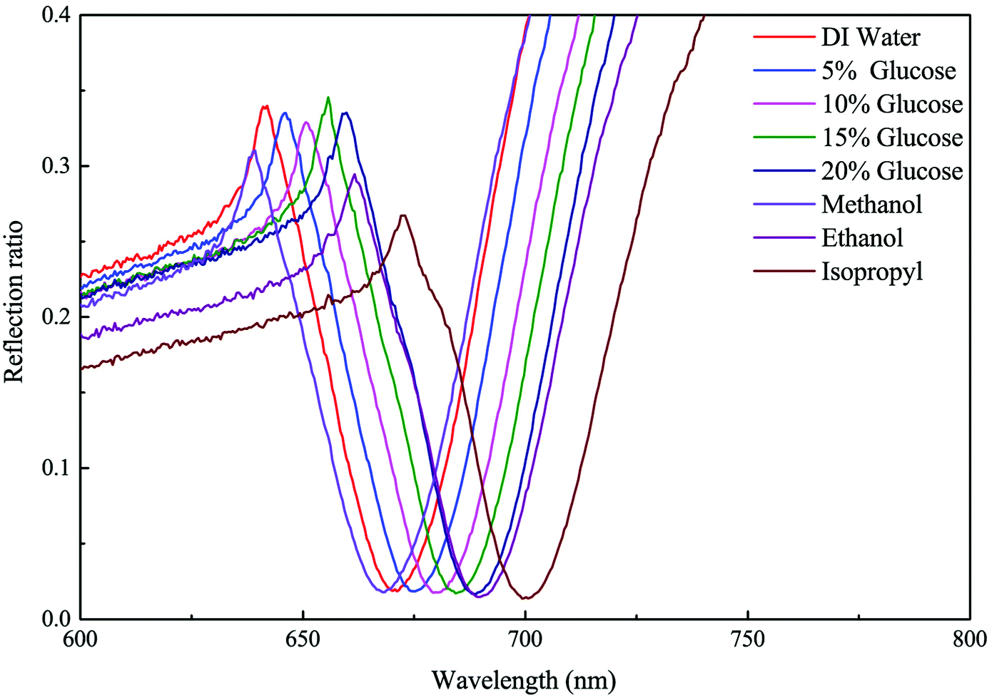 | ||
| Fig. 5 Reflection spectra of the metal grating with different liquids on its surface. | ||
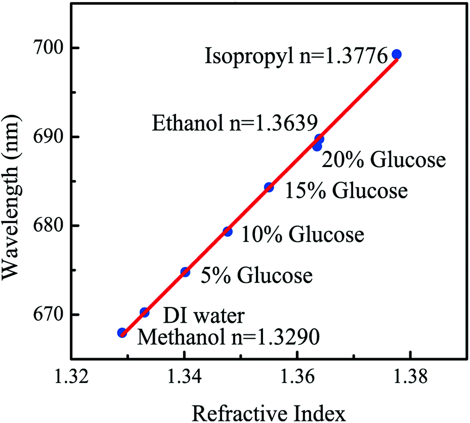
By extracting the resonant wavelength from the reflection spectra, we can plot the resonant wavelength as a function of the refractive index, which is depicted in Fig. 6. The wavelength shows a linear relationship with the refractive index, and the deviation is very small. For a SPR sensor, the sensitivity (S) and the figure of merit (FOM) are two important parameters that are widely used to quantify its performance. The sensitivity is defined as the ratio of the change of the wavelength to the change of the refractive index (S = Δλ/Δn). According to the linear fitting of the experimental data, which is shown as the red line in Fig. 6, the sensitivity of this setup is 637 nmRIU−1. The figure of merit is defined as FOM = S/FWHM, where FWHM is the full width at half maximum of the resonance. In our experiments the FWHM is less than 30 nm, and the corresponding FOM is more than 21.
 | ||
| Fig. 6 The dependence of the resonant wavelength on the refractive index. The red line is a linear fitting. | ||
In previous reports, H. Chen et al. chemically prepared five types of different gold nanoparticles. The index sensitivities of those nanoparticles range from 44 to 703 nmRIU−1 and the FOM range from 0.6 to 4.5, with their FWHM ranging from 50 to 140 nm.31 By controlling the plasmon resonance wavelength to be around 730 nm, they measured the sensitivities of gold nanocrystals of 156 to 326 nmRIU−1.32 Moreover, L. Shao et al. prepared macro-scale colloidal metal nanocrystal arrays with sizes up to 10 × 10 cm2. The refractive index sensitivity of the gold nanorod arrays is 304 nmRIU−1 and the FOM is up to 3.09.7 Recently, T. Iqbal et al. fabricated 1D gold grating using FIB etching, which has a sensitivity of 525 nmRIU−1.8 Compared with these previous reports, the metal grating prepared in this paper has comparable or even higher refractive index sensitivity. More importantly, due to the smooth surface morphology of our grating, we obtain SPR spectrum with small FWHM, resulting in a much higher FOM than those nanocrystals and nanostructures.
RIS by power modulation
RIS by wavelength modulation needs a broadband light source and a spectrometer, which increase the complexity and cost of the system. Alternatively, RIS by power modulation needs a laser and a power meter, which is more promising to design biosensors with high integration densities.17 Thus we also built a setup to demonstrate RIS by measuring the modulated power. The schematic of the setup is illustrated in Fig. 7(a). The laser beam emitted from a HeNe laser was adjusted to TM polarization. This beam passed through the tested liquid and then irradiated on the metal grating at an oblique angle. The laser beam reflected by the metal grating was diffracted into different orders. Among these diffracted beams, the zeroth order one had the highest power. The power of the first order beam is 19% of that of the zeroth order beam. Other diffraction orders were too weak to be detected. Therefore, detection of the zeroth order beam gave the best signal to noise ratio. In the experiments, the zeroth order beam was detected by a power meter and an aperture diaphragm was installed to block the high order diffracted beams and the environmental light. In order to precisely adjust the incident angle, the cuvette was mounted on a rotating platform.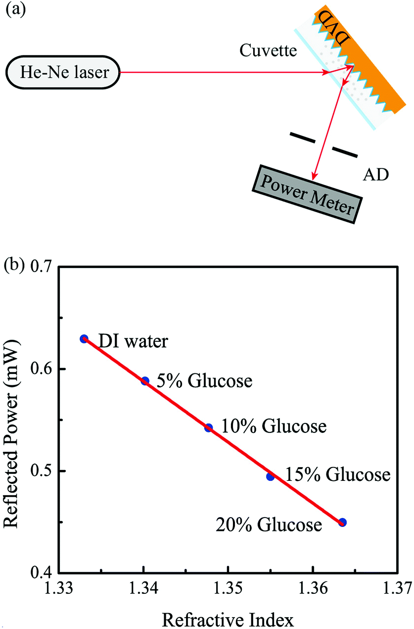 | ||
| Fig. 7 (a) Schematic of the setup to demonstrate RIS by power modulation. (b) The reflected power as a function of the refractive index. The red line is a linear fitting. | ||
According to the experimental results in the above section, our sensor has high sensitivity in the wavelength range of 600–800 nm. Therefore, we choose HeNe laser as the probing light, which has a wavelength of 632.8 nm lying in the optimal wavelength range. The incident angle of the laser beam will affect the resonant wavelength and further affect the relationship between the power and the refractive index of the dielectrics. Considering the laser wavelength of 632.8 nm, we shifted all resonant wavelengths in this experiment (corresponding to refractive index of 1.333–1.3635) to be less than 632.8 nm by setting the angle between the laser beam and the cuvette surface normal to 36 degrees. In the experiments, all reflectance measurements are performed with the same incident power of 2.14 mW.
Deionized water and glucose solutions of concentrations of 5%, 10%, 15%, 20% were tested under this configuration. Fig. 7(b) shows the reflected power as a function of the refractive index. As can be seen, the power is linearly dependent on the refractive index, which is a highly desirable property for SPR sensors. The results demonstrate that the metal layer in DVD-R disc is also suitable to design SPR sensors by power modulation. The size of the setup illustrated in Fig. 7(a) can be further reduced by replacing the HeNe laser and the power meter with a laser diode and a photodiode, respectively. This strategy promises the design of lab-on-a-chip SPR sensors.
Conclusions
In conclusion, we presented an extremely simple method to fabricate metal gratings by peeling off the metal layer from a DVD-R disc. The fabricated metal grating has a smooth sinusoidal surface profile, which can support sharp and deep SPR. Based on the metal grating, two refractive index sensors were demonstrated by either measuring the wavelength shift or the power shift. Our sensor has a high sensitivity of 637 nmRIU−1, which is comparable with or even higher than that of the existing sensors based on grating coupling. Our method largely reduces the cost to fabricate high quality metal gratings and will promote the development of grating based SPR sensors.Conflicts of interest
There are no conflicts to declare.Acknowledgements
This work is supported by the National Natural Science Foundation of China (Grant No. 61605067); The Fundamental Research Funds for the Central Universities (Grant No. JUSRP11722, No. JUSRP51721B).References
- J. Homola, S. S. Yee and G. Gauglitz, Sens. Actuators, B, 1999, 54, 3–15 CrossRef.
- J. N. Anker, W. P. Hall, O. Lyandres, N. C. Shah, J. Zhao and R. P. Van Duyne, Nat. Mater., 2008, 7, 442–453 CrossRef PubMed.
- S. Herranz, M. Bocková, M. D. Marazuela, J. Homola and M. C. Moreno-Bondi, Anal. Bioanal. Chem., 2010, 398, 2625–2634 CrossRef PubMed.
- E. Wijaya, C. Lenaerts, S. Maricot, J. Hastanin, S. Habraken, J. P. Vilcot, R. Boukherroub and S. Szunerits, Curr. Opin. Solid State Mater. Sci., 2011, 15, 208–224 CrossRef.
- B. X. Wang, IEEE J. Sel. Top. Quantum Electron., 2017, 23, 1–7 Search PubMed.
- B.-X. Wang, W.-Q. Huang and L.-L. Wang, RSC Adv., 2017, 7, 42956–42963 RSC.
- L. Shao, Q. Ruan, R. Jiang and J. Wang, Small, 2014, 10, 802–811 CrossRef PubMed.
- T. Iqbal and S. Afsheen, Plasmonics, 2017, 12, 19–25 CrossRef.
- D. C. Cullen, R. G. Brown and C. R. Lowe, Biosensors, 1987, 3, 211–225 CrossRef PubMed.
- M. J. Jory, P. S. Vukusic and J. R. Sambles, Sens. Actuators, B, 1994, 17, 203–209 CrossRef.
- J. Homola, I. Koudela and S. S. Yee, Sens. Actuators, B, 1999, 54, 16–24 CrossRef.
- M. Chamtouri, A. Dhawan, M. Besbes, J. Moreau, H. Ghalila, T. Vo-Dinh and M. Canva, Plasmonics, 2014, 9, 79–92 CrossRef.
- S. Wei, Optik, 2017, 131, 104–109 CrossRef.
- E. Kretschmann and H. Raether, Z. Naturforsch., 1968, 23A, 2135–2136 Search PubMed.
- A. Otto, Z. Phys. A: Hadrons Nucl., 1968, 216, 398–410 CrossRef.
- J. H. Ahn, T. Y. Seong, W. M. Kim, T. S. Lee, I. Kim and K.-S. Lee, Opt. Express, 2012, 20, 21729–21738 CrossRef PubMed.
- B. Turker, H. Guner, S. Ayas, O. O. Ekiz, H. Acar, M. O. Guler and A. Dâna, Lab Chip, 2011, 11, 282–287 RSC.
- H. Guner, E. Ozgur, G. Kokturk, M. Celik, E. Esen, A. E. Topal, S. Ayas, Y. Uludag, C. Elbuken and A. Dana, Sens. Actuators, B, 2017, 239, 571–577 CrossRef.
- O. Telezhnikova and J. Homola, Opt. Lett., 2006, 31, 3339–3341 CrossRef PubMed.
- M. Piliarik, M. Vala, I. Tichý and J. Homola, Biosens. Bioelectron., 2009, 24, 3430–3435 CrossRef PubMed.
- M. Vala, K. Chadt, M. Piliarik and J. Homola, Sens. Actuators, B, 2010, 148, 544–549 CrossRef.
- G. A. López-Muñoz, M. C. Estevez, E. C. Peláez-Gutierrez, A. Homs-Corbera, M. C. García-Hernandez, J. I. Imbaud and L. M. Lechuga, Biosens. Bioelectron., 2017, 96, 260–267 CrossRef PubMed.
- J. Cao, Y. Sun, H. Zhu, M. Cao, X. Zhang and S. Gao, Plasmonics, 2017 DOI:10.1007/s11468-017-0663-5.
- J. Dostálek, J. Homola and M. Miler, Sens. Actuators, B, 2005, 107, 154–161 CrossRef.
- G. Li, Y. Shen, G. Xiao and C. Jin, Opt. Express, 2015, 23, 8995–9003 CrossRef PubMed.
- C.-C. Yu, K.-H. Ho, H.-L. Chen, S.-Y. Chuang, S.-C. Tseng and W.-F. Su, Biosens. Bioelectron., 2012, 33, 267–273 CrossRef PubMed.
- B. Xiao, S. K. Pradhan, K. C. Santiago, G. N. Rutherford and A. K. Pradhan, Sci. Rep., 2016, 6, 24385 CrossRef PubMed.
- B. Kaplan, H. Guner, O. Senlik, K. Gurel, M. Bayindir and A. Dana, Plasmonics, 2009, 4, 237–243 CrossRef.
- W. H. Yeh, J. W. Petefish and A. C. Hillier, Anal. Chem., 2011, 83, 6047–6053 CrossRef PubMed.
- H. Raether, Surface Plasmons on Smooth and Rough Surfaces and on Gratings, Springer Berlin Heidelberg, 1988 Search PubMed.
- H. Chen, X. Kou, Z. Yang, W. Ni and J. Wang, Langmuir, 2008, 24, 5233–5237 CrossRef PubMed.
- H. Chen, L. Shao, K. C. Woo, T. Ming, H.-Q. Lin and J. Wang, J. Phys. Chem. C, 2009, 113, 17691–17697 CrossRef.
| This journal is © The Royal Society of Chemistry 2018 |