DOI:
10.1039/C8RA03015D
(Paper)
RSC Adv., 2018,
8, 17489-17496
Fe3O4 nanoparticles decorated on a CuS platelet-based sphere: a popcorn chicken-like heterostructure as an ideal material against electromagnetic pollution†
Received
8th April 2018
, Accepted 28th April 2018
First published on 14th May 2018
Abstract
Electromagnetic irradiation has caused environmental pollution and harmful effects on human health. The use of effective materials to attenuate electromagnetic energy is urgently required. In this study, Fe3O4 nanoparticles (NPs) decorated on a CuS platelet-based sphere (CuS/Fe3O4) with popcorn chicken-like micromorphology were synthesized through a solvothermal deposition method. The effects of reaction temperature and quantity of Fe3O4 NPs on the heterostructures, morphologies and electromagnetic absorption (EA) properties of the heterostructures were investigated. CuS/Fe3O4 heterostructures exhibited remarkable enhancement in comparison with pure Fe3O4 NPs and the CuS platelet-based sphere. With the contribution from dielectric and magnetic losses, a CuS/Fe3O4 heterostructure-loaded composite could achieve a minimum reflection loss (RL) of −61.32 dB at 14.00 GHz and an effective EA bandwidth (≤−10 dB) of 4.15 GHz at a thickness of only 1.5 mm simultaneously. The current study indicates that the CuS/Fe3O4 heterostructures can potentially be applied as advanced electromagnetic absorbers.
Introduction
Nowadays, increasing scientific interest is focused on protection from electromagnetic irradiation, which occurs due to the wide-range operation of wireless communication devices and the application of electromagnetic devices in both civil society and the military.1–5 Consequently, developing electromagnetic absorption (EA) materials is an urgent countermeasure, which is required to deal with the various harmful effects of electromagnetic irradiation on humans and on the environment. These materials can dissipate or transform the energy of electromagnetic radiation into thermal energy. A variety of studies have been devoted to the synthesis of EA materials to obtain EA materials having properties such as strong absorption capability, wide effective absorption bandwidth, high thermal stability, lightweightedness, and anti-oxidation.6–8
With the development of technology, various strategies have been explored to synthesize functional materials to achieve better EA performance; these materials include metal oxides or sulfides, such as ZnO,9 CoFe2O4,10 SnO2,11 CoS,12 and CuS13–15 as well as carbon materials such as carbon nanotubes (CNTs),16,17 graphene or reduced graphene oxide (RGO),18 carbon fibers (CFs),19 and/or their hybrids.20,21 Among the many existing materials, heterostructures of magnetic loss-type and dielectric loss-type materials produce great enhancement in EA performance; these materials include Fe3O4/CuSiO3,22 Fe/SnO2,10 CoFe2O4/GO (graphene oxide),1 Ni/CuO23 and Fe3O4/CNTs,24 which are promising in the EA field.
Copper sulfide (CuS), an important semiconductor transition-metal chalcogenide with unique electronic properties, is a perspective material with wide application in the fields of sensing,25 imaging,26 hydrogen storage,27 lithium-ion batteries,28 etc. To date, a variety of CuS structures such as 0D nanoparticles,29 1D nanotubes,25 nanowires,30 2D nanoplates,31 and 3D porous hollow flowers32 have been fabricated. Previous studies have explored EA values of CuS composites or their hybrids such as flower-like CuS,32 graphene CuS,33 and CuS/ZnS.34 High performance EA mainly originates from the dielectric characteristic of CuS, the dominant dipolar polarization and the associated relaxation phenomena.
Previous studies revealed the principle that hybrids of magnetic and dielectric components can improve the balance of the electromagnetic parameters, which leads to good impedance matching. Motivated by the above-mentioned requirements, in this study, we fabricated a popcorn chicken-like Fe3O4 nanoparticle (NP)-decorated CuS heterostructure (CSF) for improving EA properties by using a solvothermal method. The incorporation of the Fe3O4 NPs into CuS may induce effective interfaces between the dielectric and magnetic materials, which has the convenience in terms of matching complex permittivities and permeabilities. The probable growth mechanism of the heterostructure is discussed. The structure and morphology as well as EA properties in the frequency range of 2–18 GHz have been investigated in detail. Although some existing CuS/Fe3O4-based composites have been reported for various applications,35–37 such a study involving popcorn chicken-like Fe3O4 NPs decorated on a CuS heterostructure applied as an EA material has not been reported. The results show that CSF is a promising candidate, which may generate a new platform for developing high performance EA materials.
Experimental section
Materials
Ferric chloride (FeCl3·6H2O), sodium citrate (Na3C6H5O7·2H2O), sodium acetate (NaOAc), and copper sulfate pentahydrate (CuSO4·5H2O) were commercially obtained from Aladdin Chemical Reagent. Cetyltrimethylammonium bromide (CTAB), sulfur powder (S) and ethylene glycol (EG) were obtained from Kelong Chemical Co. Ltd. All the reagents were used without further purification.
Preparation of Fe3O4 nanoparticles
Fe3O4 NPs were prepared by a solvothermal method, as reported previously.38 FeCl3·6H2O (4.3 g) and sodium citrate (1.0 g) were dissolved in EG (70 mL) under magnetic stirring. Then, NaOAc (4.0 g) was slowly introduced into the mixture solution to generate a transparent suspension. The resulting solution was then transferred into a Teflon-lined stainless steel autoclave (100 mL capacity). Subsequently, upon sealing, the autoclave was maintained at 200 °C for 10 h. After cooling down to room temperature, the precipitate was separated magnetically and washed with absolute ethanol and deionized water several times; then, it was dried in a vacuum oven at 50 °C for 12 h.
Preparation of CuS/Fe3O4 heterostructures
Fe3O4 NPs (0.05 g) and 0.25 g CuSO4·5H2O were dissolved in a beaker containing 50 mL EG, and this solution was ultrasonically dispersed for 15 min. Then, 0.364 g CTAB was added to the solution with vigorous mechanical stirring for 30 min. Next, 0.064 g S powder was introduced into the mixed solution and stirred for another 30 min. The resulting solution was obtained and then sealed in a Teflon-lined autoclave with a capacity of 100 mL at 160 °C for 15 h. The as-synthesized black product was centrifuged, rinsed with distilled water and ethanol several times to remove any salt, denoted as CSF-160, and then dried under vacuum at 50 °C for 6 h. For comparison, different CSFs were prepared by adding different mass ratios of Fe3O4 NPs (0.025 g and 0.075 g) using a similar method, and they were marked as CSF-0.025 and CSF-0.075. Furthermore, to investigate the influence of temperature on the structure and property of CSF, the products were collected at reaction temperatures of 140 °C and 180 °C and marked as CSF-140 and CSF-180. Pristine CuS platelet-based spheres were also synthesized in a similar way without the addition of Fe3O4 NPs.
Characterization
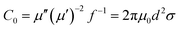
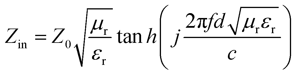
The structural analyses of CSF were carried out by X-ray diffraction (XRD) using a Rigaku X-ray diffractometer with monochromatic Cu Kα radiation (λ = 1.541 Å) at 36 kV. Further evidence for the composition of the product was inferred from X-ray photoelectron spectroscopy (XPS) using the Thermo Scientific ESCALab 250Xi A1440 system. The morphology and size distribution were characterized by sputtering with gold for scanning electron microscopy (SEM, Hitachi S-4800) at an accelerating voltage of 15 kV. Transmission electron microscopy (TEM) and High Resolution-TEM (HRTEM) measurements were carried out using a JEOL-2100 at an accelerating voltage of 200 kV. The electromagnetic parameters of complex relative permeability (μr = μ′ − jμ′′) and permittivity (εr = ε′ − jε′′) in the frequency range of 2–18 GHz for the simulation of the reflection loss (RL) were obtained using a vector network analyzer, Agilent, N5230A. The as-prepared samples were mixed with paraffin (employed as the binder) at a certain mass ratio and pressed into toroidal-shaped samples (inner diameter of 3.04 mm and outer diameter of 7.00 mm). According to the transmission line theory, theoretical RL of heterostructures having different thicknesses can be calculated using the relative complex permittivity and permeability at a given frequency by the following equations:39–41| |
 | (1) |
| |
 | (2) |
Here, Z0 is the impedance of free space, Zin is the normalized input impedance of the absorber, d is the thickness, c is the velocity of electromagnetic wave in free space and f is the frequency of the incident wave; these are the determining factors of the EA materials.42 RL values of −10 and −20 dB correspond to 90% and 99% attenuation, respectively, of the incident electromagnetic wave, and the frequency range where RL is smaller than −10 dB is defined as the effective absorption bandwidth. In general, materials with RL values of less than −10 dB are considered as qualified EA materials.
Results and discussion
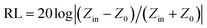
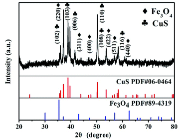
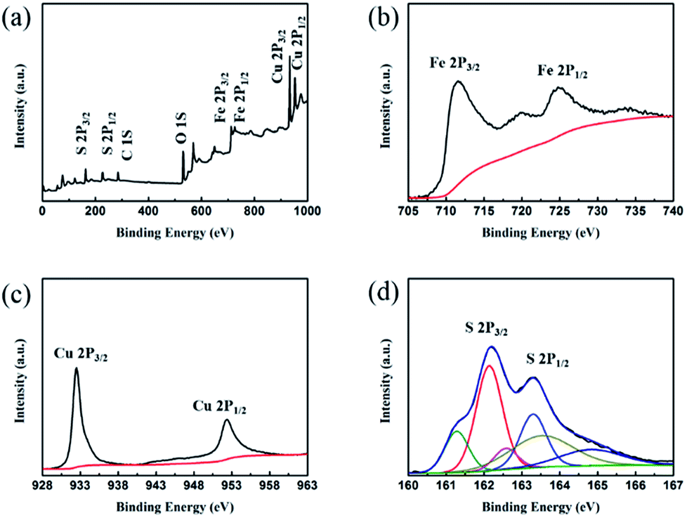
Crystal structures of the synthesized CSF-160 were investigated by XRD, and the phase and purity of the product were determined from the results, as shown in Fig. 1. From the XRD pattern, the main peaks of Fe3O4 were observed at 2θ values of 29.85°, 35.59°, 43.10°, 52.83°, 57.02° and 63.04° corresponding to (220), (311), (400), (422), (511) and (440) Bragg reflections, respectively. Furthermore, these diffraction peaks matched well with those of the standard XRD pattern of Fe3O4 with cubic spinel structure (PDF#89-4319). This result indicated that the crystallinity of Fe3O4 remained unchanged after the introduction of CuS. In addition, the remaining diffraction peaks located at 29.01°, 30.69°, 32.75°, 48.03°, 53.15° and 59.41° were due to (102), (103), (006), (110), (108) and (116) planes, which could be well indexed to the pure hexagonal phase of CuS (PDF#06-0464). The (220) plane of Fe3O4 was very close to the (103) plane of CuS; thus, the two peaks overlapped and could not be easily distinguished. Since no other clear impurity peaks appeared, it was concluded that CSF-160 has good crystallinity. Surface elemental states of CSF-160 were further analysed by XPS to further demonstrate the formation of CSF-160, and the results were consistent with the XRD patterns. From the typical survey spectrum depicted in Fig. 2a, we can find that CSF-160 was mainly composed of Cu, Fe, S and O elements. Fig. 2b shows the Fe 2p spectrum, and the main peaks at 711.6 eV and 725.3 eV corresponded to the band energies of Fe 2p3/2 and Fe 2p1/2, respectively; this indicated the generation of Fe(II) and Fe(III) oxides, which was in good agreement with the literature results and consistent with that of Fe3O4.43 In the high-resolution spectrum of Cu 2p (Fig. 2c), the sharp peaks at 932.5 eV and 952.4 eV could be assigned to Cu 2p3/2 and Cu 2p1/2, respectively. These peaks revealed Cu(II) binding energies and the presence of Cu2+ oxidation state in the product.44,45 Fig. 2d shows the S 2p spectrum with the main peaks at 162.2 eV and 163.3 eV; these results exhibit identical binding energies for S2−, and they are in good agreement with the results of previous studies.46 The O1s peak (Fig. 2a) at 530.6 eV can be assigned to the O element in Fe3O4.
 |
| | Fig. 1 XRD pattern of CSF-160 heterostructure. | |
 |
| | Fig. 2 XPS spectra of CSF-160 heterostructure: survey spectrum (a), Fe 2p binding energy spectrum (b), Cu 2p binding energy spectrum (c) and S 2p binding energy spectrum (d). | |
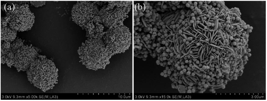
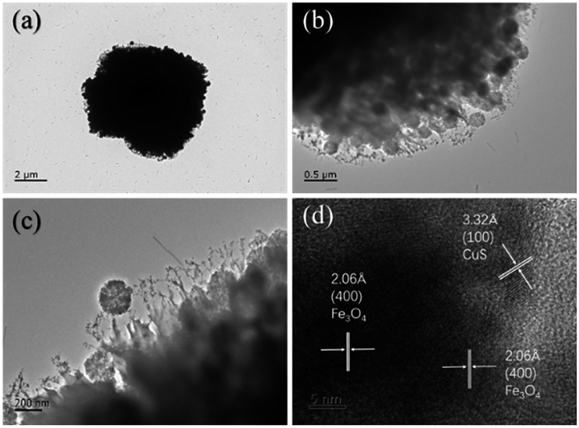
The morphologies and microstructures of the starting Fe3O4 and CuS used in this study were characterized by SEM and TEM. In Fig. S1a–c,† different magnification TEM images of Fe3O4 NPs are displayed. It can be seen that Fe3O4 NPs possessed a relatively uniform spherical shape with diameter distributions in the range of 250–300 nm. The high magnification TEM image (Fig. S1c†) demonstrates that the rough surfaces of Fe3O4 NPs were caused by the formation of many small primary nanocrystals. The morphology of pristine CuS revealed a flower-like structure with a diameter of about 3 μm, and the flower-like structured pristine CuS was composed of thin disordered nanoflakes with an average thickness of about 10 nm. This unique structure endowed CuS with a specific surface area, and it was noticed that the interspace between the nanoflakes could be a suitable position for generating a bond with Fe3O4 NPs. Fig. 3 displays the morphology of the as-synthesized CSF-160. Unlike some reported CuS/Fe3O4 composites, which always possess a core–shell structure, CSF-160 exhibited a sphere-like structure, and its surface architecture looked like popcorn chicken. Each ‘popcorn chicken’ possessed nearly uniform shape with an average size of ∼4 μm, and it was observed that Fe3O4 NPs were embedded in the interface between the nanoflakes. We consider that such a framework plays a significant role in providing suitable positions for Fe3O4 NPs as well as extending the microscopic dimensions. To further confirm the formation of CSF-160, TEM and HRTEM characterizations were carried out (Fig. 4). Fig. 4a–c display different magnification TEM images of CSF-160; the dark particle validates that the CuS crystal is solid, whereas the transparent boundary indicates that CuS has a hierarchical and crumpled surface. The heterostructure is perfectly maintained for the morphology of ‘popcorn chicken’, and there are many NPs located at the interspace of the hierarchical surface, which further demonstrated the existence of the decorated Fe3O4 NPs. The nanoflakes on the edge of CuS and the embedded Fe3O4 NPs could be observed. Such a unique surface endowed CSF-160 with a very complex surface area, thus making the incident electromagnetic wave contact fully with the heterostructure. The HRTEM image, as shown in Fig. 4d, clearly indicated the highly crystalline nature of the crystals. It was found that the lattice fringe was 3.32 Å, corresponding to the (100) plane of CuS. Furthermore, the lattice distance between two adjacent planes was 2.06 Å, corresponding to the spacing between two (400) planes in the spinel-structured Fe3O4. All these results validated that popcorn chicken-like Fe3O4 NP-decorated CuS heterostructure has been successfully synthesized through this method.
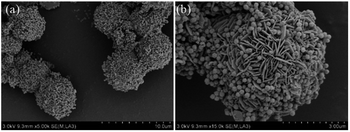 |
| | Fig. 3 Different magnification SEM images (a and b) of CSF-160 heterostructure. | |
 |
| | Fig. 4 Different magnification TEM images (a–c) and HRTEM images (d) of CSF-160 heterostructure. | |
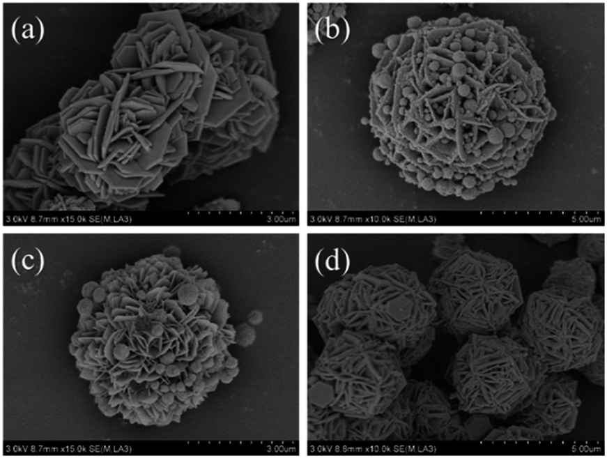
The influences of the concentration of precursor and temperature of the solvothermal reaction on the morphologies as well as EA of CSF were investigated, and the results are shown in Fig. 5. Typical SEM images of the heterostructures prepared with different amounts of Fe3O4 NPs are shown in Fig. 5a–b. It was observed that only CuS existed in the final product when the amount of Fe3O4 was 0.025 g (Fig. 5a), which meant that two kinds of materials could not be grown together. When the amount of Fe3O4 NPs was increased to 0.1 g (Fig. 5b), the flake-like CuS was found to be decorated with more Fe3O4 NPs when compared with CSF-160. These results suggested that the bonds between the two reagents could be effectively tuned by the amount of Fe3O4 NPs; also, the formation of 3-D flake-like CSF can hardly be accomplished if the concentration of Fe3O4 NPs fails to reach a certain threshold. The influences of the solvothermal reaction temperature on the morphologies are investigated in Fig. 5c and d. In detail, when the reaction temperature was adjusted to 140 °C, the amount of Fe3O4 NPs was found to be lesser than that for CSF-160, as shown in Fig. 4. When the reaction temperature increased to 180 °C, no Fe3O4 NPs could be found. Additionally, with an increase in the reaction temperature, the flakes of CuS became thick. This phenomenon indicated that a higher reaction temperature causes a faster crystal growth.32 It can be concluded that the temperature influences the growth of Fe3O4 NPs on CuS. Reaction conditions including solvothermal reaction temperature and concentration of Fe3O4 NPs play significant roles in the formation of CSF and the thickness of the hierarchical flakes.
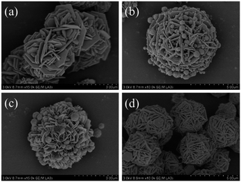 |
| | Fig. 5 SEM images of CSF heterostructures obtained under various concentrations of Fe3O4 NPs: (a) 0.025 g and (b) 0.075 g at 160 °C and SEM images of CSF heterostructures with different reaction temperatures: (c) 140 °C and (d) 180 °C. | |
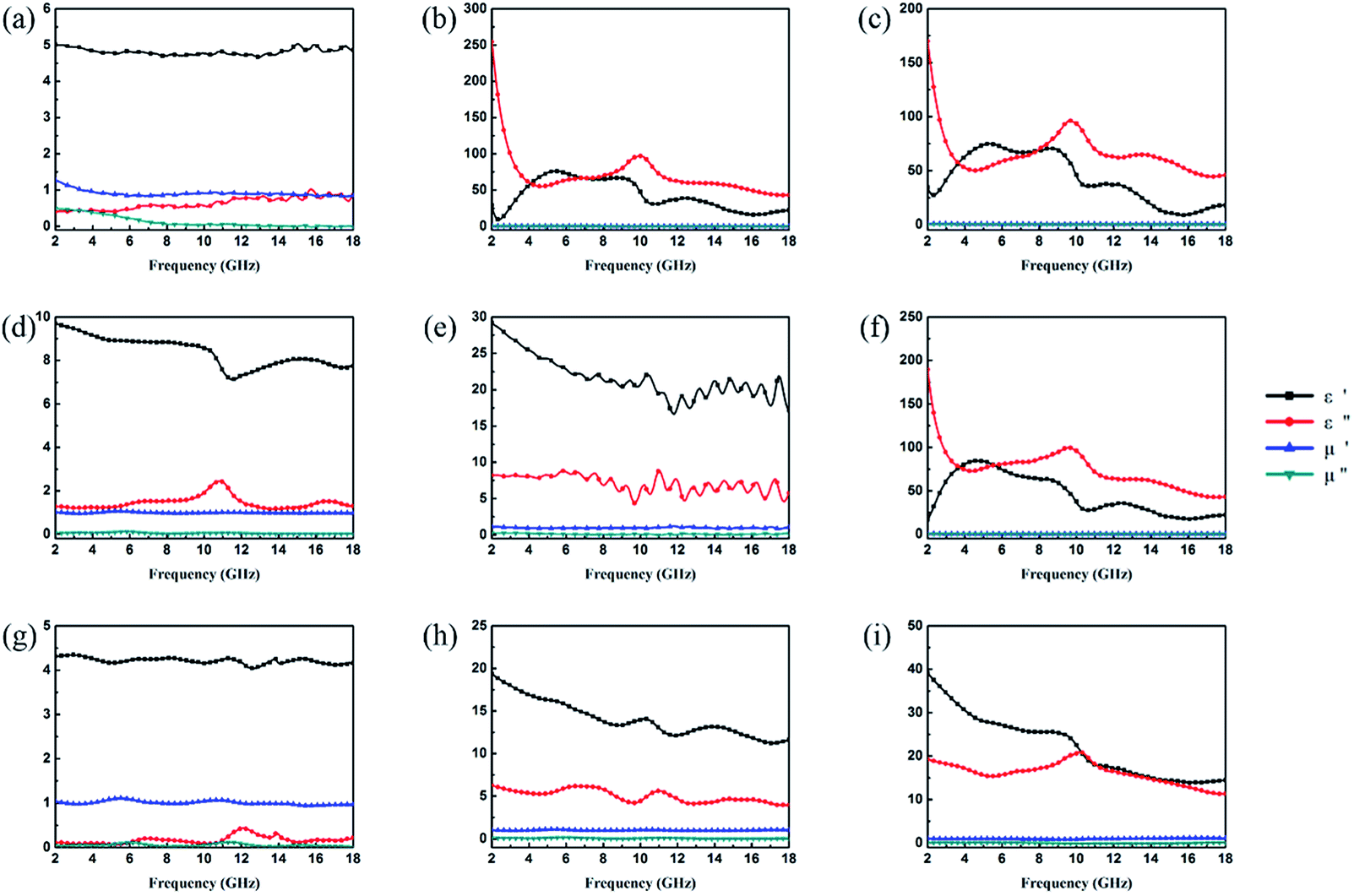
It is well-known that the EA properties are highly associated with relative complex permeability (μr = μ′ − jμ′′) and relative complex permittivity (εr = ε′ − jε′′). The real parts (μ′ and ε′) and imaginary parts (μ′′ and ε′′) of complex permeability and permittivity represent the ability to store energy and the loss of electric and magnetic energy, respectively.47 In this experiment, the electromagnetic parameters of paraffin composites containing 40 wt% pristine CuS, Fe3O4 and various kinds of CSFs were tested with a vector network analyser in the frequency range of 2–18 GHz, and the results are shown in Fig. 6. The EA mechanism of Fe3O4 consists of both dielectric loss and magnetic loss,48 which can also be proved by the values of the electromagnetic parameters shown in Fig. 6a. In addition, it was noticed that the negative values of μ′′ for Fe3O4 NPs occurred at a high frequency, which indicated that in the electromagnetic field, magnetic energy is radiated from the materials by the motion of the charges.49,50 In Fig. 6b, the value of ε′′ for CuS exhibits an abrupt decrease in the frequency range of 2–5 GHz and a fluctuation in the range of 6–18 GHz. Meanwhile, because of the absence of magnetic constituents in the material, the values of μ′ and μ′′ were approximately constant and close to 1 and 0, respectively. For various kinds of CSFs, the values of μr remained nearly unchanged, whereas the values of permittivity increased in a different scale when compared with those of Fe3O4 NPs, which was due to the dielectric property of CuS. It can be observed from Fig. 6f that the values of complex permeabilities and permittivities of CSF-180 and CuS were almost the same; this was because the high temperature destroyed the bonds between Fe3O4 NPs and CuS, and this was also proved by the SEM image (Fig. 5d). Typically, composites possessing high ε′′ values exhibit high conductivities. As shown in Fig. 6g–i, it can be noted that the values of both ε′ and ε′′ increased greatly with an increase in filler loading. When the filler loading was 30 wt%, the values of ε′ and ε′′ were in the range of 4.02–4.35 and 0.06–0.44, respectively. When the filler loading was increased to 40 wt%, the values of ε′ and ε′′ were in the range of 11.63–19.36 and 3.90–6.27, respectively. Meanwhile, the values of μ′ and μ′′ remained nearly unchanged in the whole frequency range.
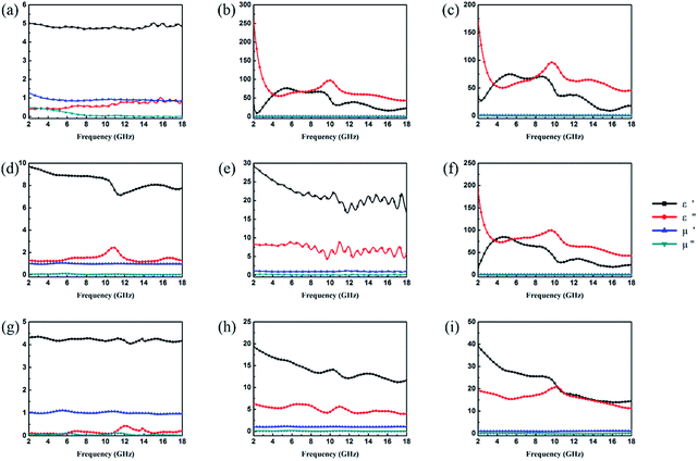 |
| | Fig. 6 Frequency dependence of real and imaginary parts of complex permittivity and permeability of Fe3O4 (a), CuS (b), CSF-0.025 (c), CSF-0.075 (d), CSF-140 (e) and CSF-180 (f) with a filler loading of 50 wt% and those of CSF-160 heterostructure with filler loadings of 30 wt% (g), 40 wt% (h) and 50 wt% (i). | |
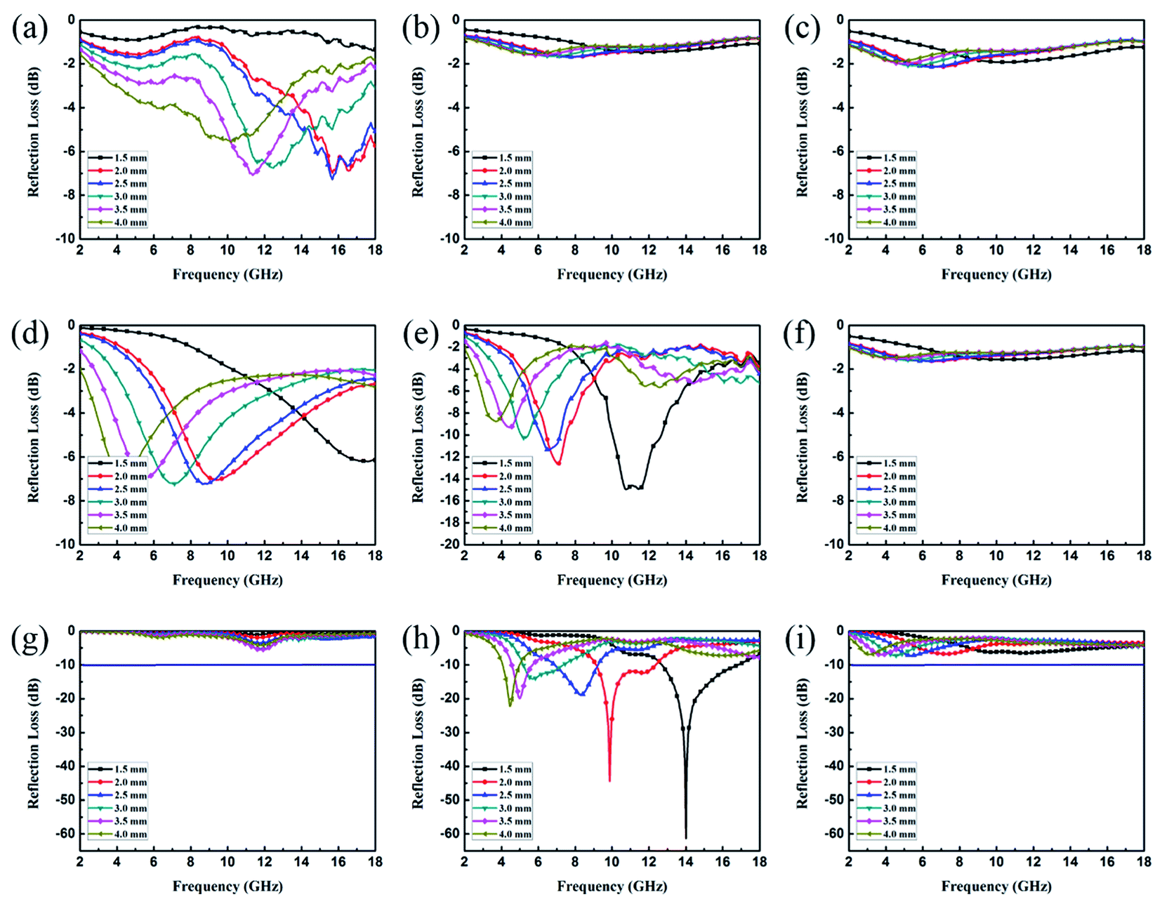
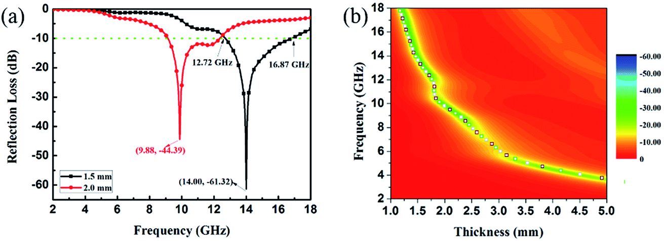
EA performance can be further quantitatively evaluated by the value of RL, which can be calculated according to eqn (1) and (2). Fig. 7 shows the RL values of various composites in the frequency range of 2–18 GHz with different thicknesses. One can see in Fig. 7a and b that the EA properties of both Fe3O4 and CuS are weak, and the minimum RL values are only −5.18 dB and −1.64 dB, respectively. The occurrence of a significant skin effect when the surface is irradiated by electromagnetic waves is a possible reason to explain the poor EA performance of Fe3O4 NPs. As for CuS, the higher permittivity is harmful to the impedance match, which leads to weak EA performance. It is noticed that CSF-160 with a filler loading of 40 wt% exhibits an enhanced EA property compared with other samples (CSF-0.025, CSF-0.075, CSF-140 and CSF-180). Herein, it can be concluded that the as-prepared CSF-160 possesses the characteristics of strong absorption and wide absorption bandwidth when compared with these samples. Specifically, when the thickness is only 1.5 mm, the sample achieves the best EA performance. The minimum RL value is −61.32 dB at 14.00 GHz, corresponding to a bandwidth of 4.15 GHz (12.72–16.87 GHz) (Fig. 8a). Such an enhanced EA property can be due to dielectric loss, magnetic loss and proper impedance matching induced by the interfacial polarization relaxation. The proper amount of Fe3O4 NPs also plays a significant role in maximizing the interface effect. Furthermore, it can be observed from Fig. 7 that the RL peaks all shift toward the lower frequency region with the increasing thickness. To illustrate why the RL peaks appear at these thicknesses, the simulations of the matching thickness versus the achieved peak frequencies based on the equation:  are shown in Fig. 8b. The 2D contour maps of paraffin composites containing 40 wt% CSF-160 as well as the corresponding wavelength under the λ/4 condition are plotted. Based on the results, it can be concluded that the location of RLmin can be adjusted to the application in different frequencies by manipulating the thickness of the composites.
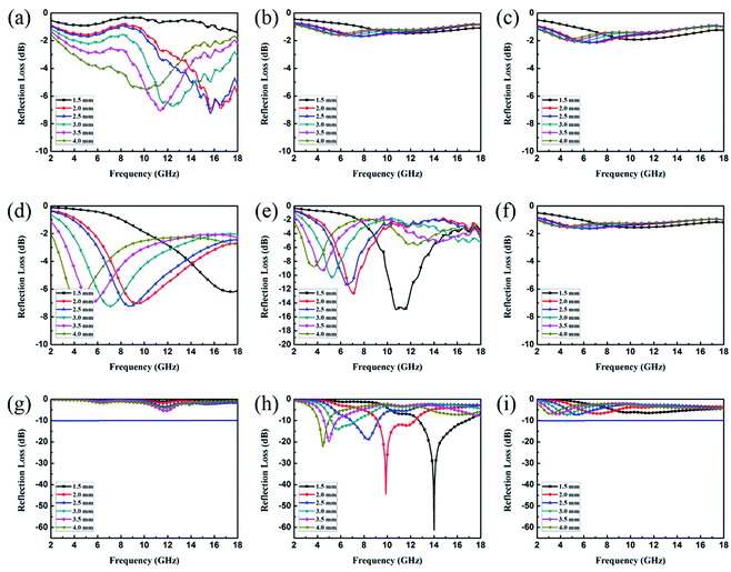 |
| | Fig. 7 RL curves of Fe3O4 (a), CuS (b), CSF-0.025 (c), CSF-0.075 (d), CSF-140 (e) and CSF-180 (f) with a filler loading of 50 wt% and those of CSF-160 heterostructure with filler loadings of 30 wt% (g), 40 wt% (h) and 50 wt% (i); the testing frequency range is 2–18 GHz. | |
 |
| | Fig. 8 RL curves of CSF-160 heterostructure loaded with 40 wt% under thicknesses of 1.5 mm and 2.0 mm (a); 2D RL contour maps of CSF-160 heterostructure loaded with 40 wt% and the calculated matching thickness according to the λ/4 model (b). | |
According to van der Zaag's research achievements, magnetic loss is mainly due to hysteresis, domain wall resonance, natural resonance and eddy current resonance. In general, hysteresis loss is negligible in a weak field, and domain wall resonance loss takes place in a MHz frequency. The following equation is used to discuss whether an eddy current makes a contribution to the magnetic loss:51
| |
 | (3) |
Here,
C0 is the eddy current loss,
d is the thickness of the absorber,
σ is the electrical conductivity, and
μ0 is the permeability in vacuum. If the magnetic loss only stems from the eddy current,
C0 should be constant when the frequency varies; if not, the magnetic loss is ascribed to natural resonance.
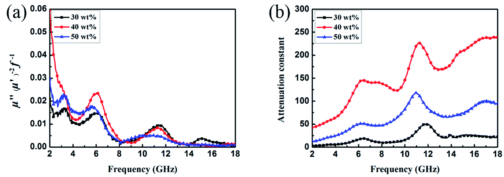
Fig. 9a shows the
C0 curves for CSF-160 with filler loadings of 30 wt%, 40 wt% and 50 wt%. The value curves show a fluctuating trend and vary with the frequency in the range of 2–18 GHz. It can be concluded that eddy current effect is absent, and magnetic loss mainly results from the natural resonance. The attenuation constant,
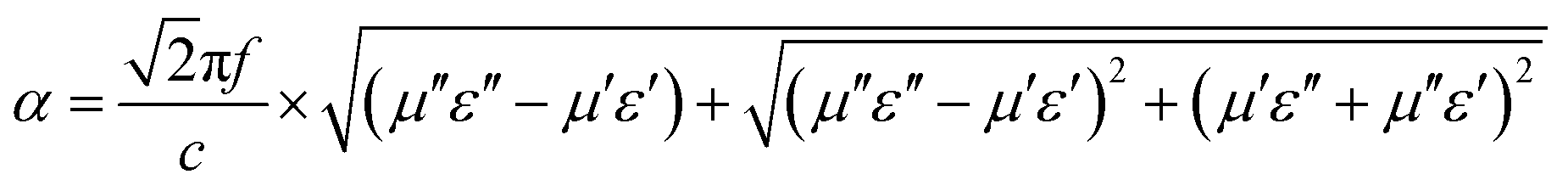
α, evaluates the dissipation ability of the absorber and can be expressed by the following equation:
52| |
 | (4) |
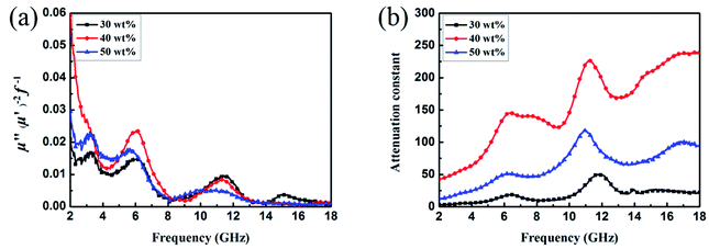 |
| | Fig. 9 Frequency dependence of C0 (a) and values of attenuation constant (b) of CSF-160 heterostructure. | |
Fig. 9b shows the plot of the values of attenuation constant, α, versus frequency. A larger attenuation constant results in more electromagnetic wave attenuation, which is beneficial to the wave absorption performance. It can be seen that CSF-160 with 40 wt% filler loading has the largest value of α, and the curve of α shows an increasing trend with small fluctuation versus frequency. It can be considered that paraffin composites containing 40 wt% CSF-160 possess greater electromagnetic wave attenuation. The loss tangent can be calculated based on the electromagnetic parameters, and the results are shown in Fig. S2.† We obtain the following observations: the frequency dependence of tan![[thin space (1/6-em)]](https://www.rsc.org/images/entities/char_2009.gif) δμ exhibits very similar variation trend, whereas tanδε of 40 wt% CSF filler loading displays a larger value than the other two samples. In this regard, the dielectric loss rather than the magnetic loss contributes mainly to the EA of this sample.
δμ exhibits very similar variation trend, whereas tanδε of 40 wt% CSF filler loading displays a larger value than the other two samples. In this regard, the dielectric loss rather than the magnetic loss contributes mainly to the EA of this sample.
To the best of our knowledge, there are no previous related reports on CuS/Fe3O4-based heterostructures as EA materials. In Table 1,† we have summarized the EA performances of some other CuS-based materials, which have been published in recent years. The result indicates that the as-prepared popcorn chicken-like CSF displays the strongest absorption property and a broader absorption bandwidth with a thin absorber thickness (1.5 mm). It can be concluded that the popcorn chicken-like Fe3O4 NP-decorated CuS heterostructure has the potential to alleviate the electromagnetic pollution problem.
Conclusion
In summary, a popcorn chicken-like Fe3O4 NP-decorated CuS heterostructure has been synthesized by a simple solvothermal method. The morphology of the as-prepared CuS/Fe3O4 heterostructure is controlled by the temperature and the amount of Fe3O4 NPs. By adjusting the reaction conditions, five different types of CuS/Fe3O4 have been obtained. The formation mechanism of the heterostructure has been investigated based on XRD, XPS, SEM and TEM results. Different CuS/Fe3O4 heterostructures show variable EA responses, where the optimum value is obtained at 160 °C with the addition of 0.05 g Fe3O4 NPs, and this heterostructure exhibits the strongest absorbing capability. Specifically, the optimal RL value is −61.32 dB at 14.00 GHz with an absorber thickness of only 1.5 mm, corresponding to a bandwidth of 4.15 GHz (12.72–16.87 GHz). The superior absorption can be ascribed to an appropriate impedance matching, the synergistic effect of the magnetic loss in Fe3O4 NPs and the dielectric loss in CuS as well as interfacial polarization relaxation. The unique microstructure is also considered to be responsible for constructing multiple reflections. As a result, this novel popcorn chicken-like Fe3O4 NP-decorated CuS heterostructure has potential applications in the prevention of electromagnetic wave pollution.
Conflicts of interest
The authors declare no competing financial interest.
Acknowledgements
This study was financially supported by the Natural Science Foundation of Jiangsu Province (BK20161466).
Notes and references
- X. Li, J. Feng, Y. Du, J. Bai, H. Fan, H. Zhang, Y. Peng and F. Li, J. Mater. Chem. A, 2015, 3, 5535 Search PubMed.
- J. Chen, M. Liu, T. Yang, F. Zhai, X. Hou and K. Chou, CrystEngComm, 2017, 19, 519 RSC.
- J. Feng, Y. Wang, Y. Hou and L. Li, Inorg. Chem. Front., 2017, 4, 935 RSC.
- L. Wang, H. Xing, S. Gao, X. Ji and Z. Shen, J. Mater. Chem. C, 2017, 5, 2005 RSC.
- Z. J. Li, Z. L. Hou, W. L. Song, X. D. Liu, W. Q. Cao, X. H. Shao and M. S. Cao, Nanoscale, 2016, 8, 10415 RSC.
- W. Feng, Y. Wang, J. Chen, L. Guo, J. Ouyang, D. Jia and Y. Zhou, Phys. Chem. Chem. Phys., 2017, 19, 14596 RSC.
- C. Hu, Z. Mou, G. Lu, N. Chen, Z. Dong, M. Hu and L. Qu, Phys. Chem. Chem. Phys., 2013, 15, 13038 RSC.
- A. A. Amer, S. M. Reda, M. A. Mousa and M. M. Mohamed, RSC Adv., 2017, 7, 826 RSC.
- G. Wang, Y. Wu, X. Zhang, Y. Li, L. Guo and M. Cao, J. Mater. Chem. A, 2014, 2, 8644 Search PubMed.
- S. Zhang, Q. Jiao, Y. Zhao, H. Li and Q. Wu, J. Mater. Chem. A, 2014, 2, 18033 Search PubMed.
- B. Zhao, B. Fan, Y. Xu, G. Shao, X. Wang, W. Zhao and R. Zhang, ACS Appl. Mater. Interfaces, 2015, 7, 26217 Search PubMed.
- T. Huang, M. He, Y. Zhou, S. Li, B. Ding, W. Pan, S. Huang and Y. Tong, RSC Adv., 2016, 6, 100392–100400 RSC.
- E. Sano and E. Akiba, Carbon, 2014, 78, 463 CrossRef.
- O. V. Sedelnikova, M. A. Kanygin, E. Yu. Korovin, L. G. Bu-lusheva, V. I. Suslyaev and A. V. Okotrub, Compos. Sci. Tech-nol., 2014, 102, 59 CrossRef.
- N. Wang, F. Wu, A. Xie, X. Dai, M. Sun, Y. Qiu, Y. Wang, X. Lv and M. Wang, RSC Adv., 2015, 5, 40531 RSC.
- E. Sano and E. Akiba, Carbon, 2014, 78, 463 CrossRef.
- S. Yun, A. Kirakosyan, S. Surabhi, J.-R. Jeong and J. Choi, J. Mater. Chem. C, 2017, 5, 8436 RSC.
- S. Fang, D. Huang, R. Lv, Y. Bai, Z.-H. Huang, J. Gu and F. Kang, RSC Adv., 2017, 7, 25773 RSC.
- X. Wang, X. Huang, Z. Chen, X. Liao, C. Liu and B. Shi, J. Mater. Chem. C, 2015, 3, 10146 RSC.
- I. Arief, S. Biswas and S. Bose, ACS Appl. Mater. Interfaces, 2017, 9, 19202 Search PubMed.
- P. Yan, J. Miao, J. Cao, H. Zhang, C. Wang, A. Xie and Y. Shen, J. Mater. Sci., 2017, 52, 13078 CrossRef.
- J. Xu, J. Liu, R. Che, C. Liang, M. Cao, Y. Li and Z. Liu, Nanoscale, 2014, 6, 5782 RSC.
- B. Zhao, G. Shao, B. Fan, W. Zhao and R. Zhang, Phys. Chem. Chem. Phys., 2015, 17, 6044 RSC.
- L. Zhu, X. Zeng, M. Chen and R. Yu, RSC Adv., 2017, 7, 26801 RSC.
- X. Zhang, G. Wang, A. Gu, Y. Wei and B. Fang, Chem. Commun., 2008, 45, 5945 RSC.
- L. Wang, RSC Adv., 2016, 6, 82596 RSC.
- A. A. Dubale, A. G. Tamirat, H. Chen, T. A. Berhe, C. Pan, W. Su and B. Hwang, J. Mater. Chem. A, 2016, 4, 2205 Search PubMed.
- X. Li, K. Hu, R. Tang, K. Zhao and Y. Ding, RSC Adv., 2016, 6, 71319 RSC.
- W. Zhang, Y. Sun, Z. Xiao, W. Li, B. Li, X. Huang, X. Liu and J. Hu, J. Mater. Chem. A, 2015, 3, 7304 Search PubMed.
- S. Wang, S. Yang, Z. Rong Dai and Z. L. Wang, Phys. Chem. Chem. Phys., 2001, 3, 3750 RSC.
- W. Fu, M. Liu, F. Xue, X. Wang, Z. Diao and L. Guo, RSC Adv., 2016, 6, 80361 RSC.
- B. Zhao, X. Guo, Y. Zhou, T. Su, C. Ma and R. Zhang, CrystEngComm, 2017, 19, 2178 RSC.
- X. Zhang, G. Wang, Y. Wei, L. Guo and M. Cao, J. Mater. Chem. A, 2013, 1, 12115 Search PubMed.
- X. Guan, P. Qu, X. Guan and G. Wang, RSC Adv., 2014, 4, 15579 RSC.
- B. Zhang, Y. Shan and K. Chen, Mater. Chem. Phys., 2017, 193, 82 CrossRef.
- M. H. Beyki, M. Shirkhodaie and F. Shemirani, Anal. Methods, 2016, 8, 1351 RSC.
- Z. Wu, W. Li, C. Luo, C. Su and C. Yeh, Adv. Funct. Mater., 2015, 25, 6527 CrossRef.
- Y. Pan, G. Wang and Y. Yue, RSC Adv., 2015, 5, 71718 RSC.
- H. Guo, Y. Zhan, Z. Chen, F. Meng, J. Wei and X. Liu, J. Mater. Chem. A, 2013, 1, 2286 Search PubMed.
- W. Li, B. Lv, L. Wang, G. Li and Y. Xu, RSC Adv., 2014, 4, 55738 RSC.
- Y. Lin, L. Xu, Z. Jiang, H. Li, Z. Xie and L. Zheng, RSC Adv., 2015, 5, 70849 RSC.
- B. Lu, X. L. Dong, H. Huang, X. F. Zhang, X. G. Zhu, J. P. Lei and J. P. Sun, J. Magn. Magn. Mater., 2008, 320, 1106 CrossRef.
- Y. Liu, L. Yu, Y. Hu, C. Guo, F. Zhang and X. Lou, Nanoscale, 2012, 4, 183 RSC.
- M. R. Kim, H. A. Hafez, X. Chai, L. V. Besteiro, L. Tan, T. Ozaki, A. O. Govorov, R. Izquierdo and D. Ma, Nanoscale, 2016, 8, 12946 RSC.
- L. Cai, Y. Sun, W. Li, W. Zhang, X. Liu, D. Ding and N. Xu, RSC Adv., 2015, 5, 98136 RSC.
- P. Liu, Y. Huang, J. Yan, Y. Yang and Y. Zhao, ACS Appl. Mater. Interfaces, 2016, 8, 5536 Search PubMed.
- B. Zhong, X. Tang, X. Huang, L. Xia, X. Zhang, G. Wen and Z. Chen, CrystEngComm, 2015, 17, 2806 RSC.
- F. Meng and X. Liu, RSC Adv., 2015, 5, 7018 RSC.
- Z. Wang, L. Wu, J. Zhou, B. Shen and Z. Jiang, RSC Adv., 2013, 3, 3309 RSC.
- J. Liu, R. Che, H. Chen, F. Zhang, F. Xia, Q. Wu and M. Wang, Small, 2012, 8, 1214 CrossRef PubMed.
- Y. Li, T. Wu, K. Jiang, G. Tong, K. Jin, N. Qian, L. Zhao and T. Lv, J. Mater. Chem. C, 2016, 4, 7119 RSC.
- P. Liu, Z. Yao, J. Zhou, Z. Yang and L. B. Kong, J. Mater. Chem. C, 2016, 4, 9738 RSC.
Footnote |
| † Electronic supplementary information (ESI) available. See DOI: 10.1039/c8ra03015d |
|
| This journal is © The Royal Society of Chemistry 2018 |
Click here to see how this site uses Cookies. View our privacy policy here. 
 Open Access Article
 This Open Access Article is licensed under a Creative Commons Attribution-Non Commercial 3.0 Unported Licence
 a,
Mingxu Suia,
Guangzhen Cuia,
Ling Lia,
Xiaopeng Lic,
Xuliang Lv*a,
Fan Wu
a,
Mingxu Suia,
Guangzhen Cuia,
Ling Lia,
Xiaopeng Lic,
Xuliang Lv*a,
Fan Wu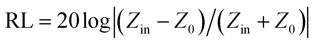

 are shown in Fig. 8b. The 2D contour maps of paraffin composites containing 40 wt% CSF-160 as well as the corresponding wavelength under the λ/4 condition are plotted. Based on the results, it can be concluded that the location of RLmin can be adjusted to the application in different frequencies by manipulating the thickness of the composites.