 Open Access Article
Polarization-independent and angle-insensitive electromagnetically induced transparent (EIT) metamaterial based on bi-air-hole dielectric resonators
Lei Zhu *ab,
Xin Zhao
 a,
Liang Dong*ac,
Jing Guod,
Xun Jun He
 e and
Zhong Min Yaoa
aCommunication and Electronics Engineering Institute, Qiqihar University, China. E-mail: zhuzhubutterfly@163.com
bCollege of Information and Communication Engineering, Harbin Engineering University, China
cSchool of Electronic Engineering, Beijing University of Posts and Telecommunications, China
dScience and Technology on Electronic Test & Measurement Laboratory, North University of China, China
eDepartment of Electronic Science and Technology, Harbin University of Science and Technology, China
First published on 31st July 2018
Abstract
We numerically demonstrate that an electromagnetically induced transparent (EIT) all-dielectric metamaterial with properties of polarization-independence and incident angle insensitivity can be achieved in terahertz regimes. The metamaterial cell is composed of two bi-air-hole cubes (BCs) with different sizes. The two BCs function as superradiant and subradiant resonators, respectively. Based on Mie-type destructive interferences between dielectric resonators, the EIT effect is induced at around 8.25 THz with the transmission peak close to 0.95. Moreover, the “two-particle” model is introduced to describe the EIT effect and the influence of couplings between the two BCs on the transmission spectra. Analytical results are in good agreement with numerical simulation results. Owing to the symmetry and uniformity of the metamaterial structure, polarization-independent and angle-insensitive properties can be achieved. In addition, the slow light characteristic of the metamaterial is also verified. Such an EIT scheme may have potential applications in low-loss slow light devices and bandpass filters.
1. Introduction
Electromagnetically induced transparency (EIT) is a coherent process in three- or multi-level atomic systems,1–3 due to which an originally opaque medium can be converted to a transparent medium over a narrow spectral range.1,4,5 This phenomenon can be explained by quantum interference between the pump and probe beams tuned at different transitions.6–8 This EIT effect is usually accompanied with strong dispersion, leading to a large value of the effective group index, which is important for slow light control.2,8,9 Besides, nonlinear optics, ultrafast switching, optical data storage, signal processing, optical delay lines and many other intriguing applications have been further developed based on the EIT effect.7,9,10 Recently, with the rapid development of metamaterials, the analog of EIT effect in metamaterials has captured significant attention of researchers. This is because the EIT effect can be easily realized in microwave, terahertz, and optical ranges.7,11,12 Moreover, compared with the EIT property in atomic systems, the EIT effect in metamaterials has the advantages of bandwidth broadening, room temperature operation, nanoscale planar devices, and the ability to integrate with nanoplasmonic circuits, which allow the use of the EIT effect in practical applications.13–15Generally, the EIT effect in metamaterials is realized based on two methods: one is the bright-dark model, and the other is the superradiant–subradiant model.13,16 The latter is usually characterized by two substructures with similar resonant frequencies but significantly different quality factors (Q-factors). To be more specific, a broad (low Q-factor) superradiant mode and a narrow (high Q-factor) subradiant mode with similar resonant frequencies need to be excited simultaneously.7,17,18 Thus, the coupling between these two modes can induce the EIT effect. This approach is much easier for the realization of the EIT effect than that of the bright-dark model. This is because both superradiant and subradiant modes can be individually obtained for excitation of incident waves. In this context, many EIT metamaterials have been reported.7,16 In these schemes, the symmetry of the metamaterial structures is broken. As a result, EIT effects in metamaterials highly depend on the polarization states of incident electromagnetic (EM) waves,3 that is, they are merely effective for one linear polarization state.15 When the polarization of incident wave changes, the EIT effect attenuates or even disappears.16 However, in practical applications, it is highly desired that the EIT effect in metamaterials should be insensitive to the polarization states of the incident EM waves.3 Therefore, it is of great significance to design polarization-independent EIT metamaterials.
Recently, it has been reported that high permittivity all-dielectric structures can generate magnetic dipoles, electric dipoles and higher order dipoles with low absorption losses due to Mie resonances.19,20 In contrast to LC resonance of metal structures, the dielectric Mie resonance is accompanied by displacement current oscillation and thus, its loss is mainly determined by dielectric loss instead of ohmic loss.21,22 Therefore, low-loss metamaterials are more easily achieved based on all-dielectric structures. Furthermore, an all-dielectric structure is not involved with the capacitance gap and thus, it is more convenient to realize low-loss metamaterials with properties of polarization-independence and incident angle insensitivity.
On the basis of the above-mentioned reasons, we propose an all-dielectric terahertz EIT metamaterial with properties of polarization independence and incident angle insensitivity. The unit cell of the metamaterial consists of two bi-air-hole cubes (BCs). A clear EIT window is obtained around 8.25 THz based on the electric and magnetic Mie resonances of the two BCs. The physical mechanism of EIT effect generation is also investigated by analysing current distributions at Mie resonances. Moreover, the “two-particle” model is used to describe the EIT effect in metamaterial. Analytical results are consistent with numerical simulation results. In addition, numerical simulation results also indicate that the transmission spectra for the proposed structure are insensitive to polarization states and incident angles of the incident waves, and it possesses the property of slow light. Such EIT metamaterials may open up new opportunities for potential applications in bandpass filters and slow light devices with low losses.
2. Structure design and simulation verification
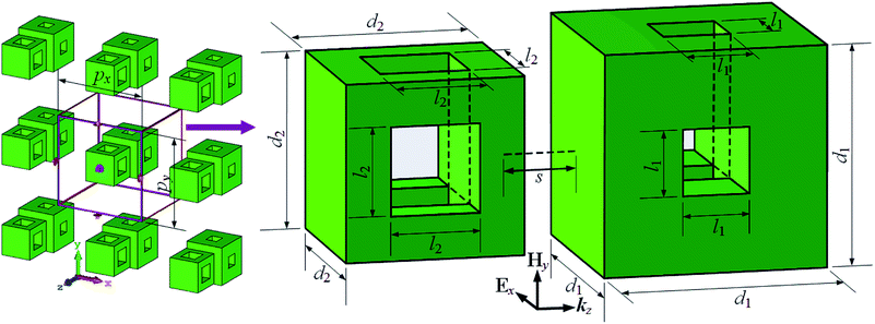
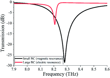
Fig. 1 shows the structure of the proposed EIT metamaterial. The unit cell of the metamaterial consists of two cubes, and each cube contains two square air holes located at the centers of its two adjacent faces. Two cubes are placed along the z-direction with a separation of s. The specific geometrical dimensions of the dielectric cubes, as shown in Fig. 1, are set as d1 = 5 μm, d2 = 4 μm, l1 = 1.5 μm, l2 = 2 μm, s = 1 μm, and px = py = 12 μm. The relative permittivity and loss tangent values of the dielectric material for the two cubes are 100 and 0.0016, respectively.23 For simulations, frequency domain solver CST Microwave Studio is used. Dielectric cubes are illuminated by a normally incident wave along the z-direction, and periodic boundary conditions are applied in x- and y-directions.We first investigate the transmission spectra of two BCs, as manifested in Fig. 2. It is shown that two dips appear around 8.28 THz and 8.21 THz in the transmission spectra of small BC and large BC, corresponding to the Mie magnetic and electric resonances (as shown in the following). To understand the resonance natures of the two dips, the corresponding E-field and H-field distributions are displayed in Fig. 3. It can be seen from Fig. 3(a) and (b) that a circular E-field and a symmetrical H-field occur in the small BC at 8.28 THz. These two features are consistent with that of the first order Mie magnetic resonance.24 Meanwhile, it is also found that a symmetrical E-field and a circular H-field appear at 8.21 THz for the large BC, as shown in Fig. 3(c) and (d), that is, the resonance dip of the large BC corresponds to Mie electric resonance; this resonance is its second resonance mode (the first resonance mode is not shown).24
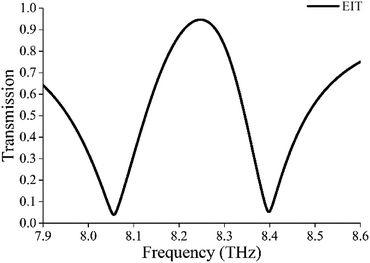
Since both BCs can be directly excited by an incident EM wave around 8.25 THz, their combination results in the EIT effect, according to the superradiant–subradiant model. In our configuration, the small BC operates as the superradiant resonator because of its wider magnetic resonance (Q = 130, calculated by Q = fc/Δf,5,25–27 where fc is the central resonant frequency and Δf is the full width of half maximum bandwidth), whereas the large BC functions as the subradiant resonator due to its narrower electric resonance (Q = 352). As a consequence, when small BC and large BC are assembled as the unit cell, as depicted in Fig. 1, the coupling between superradiant mode and subradiant mode leads to an EIT window appearing at around 8.25 THz, as shown in Fig. 4. It is also observed that the transmission peak of transparent window is about 0.95. Therefore, a low-loss EIT effect is realized using Mie resonators.
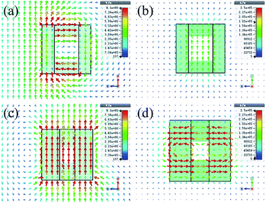
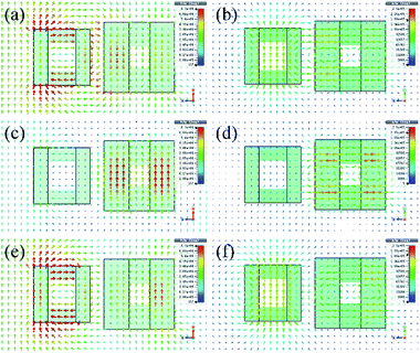
To understand the physical mechanism for the generation of the EIT effect, the E-field and H-field distributions of three key resonances for EIT windows are simulated, and the results are shown in Fig. 5. It can be found that the electric resonance of large BC and the magnetic resonance of small BC are simultaneously excited by incident waves. At the first transmission dip (8.06 THz), there are interactions of scattered EM fields in the adjacent domains of the two resonators (Fig. 5(a) and (b)). In this case, EM energies are mainly concentrated in large BC resonator, but a large part of EM energies in the two resonators is lost to free space. At the transmission peak of 8.25 THz (Fig. 5(c) and (d)), destructive interference between scattering EM fields of the two resonators occurs, and most EM energy is located at subradiant resonator of the large BC. Hence, the radiation loss of metamaterial is reduced significantly and thus, the transmission is enhanced. At the second transmission dip of 8.40 THz, as shown in Fig. 5(e) and (f), it can be seen that EM energies reassemble in the superradiant resonator, and a large amount of E-field energy is lost to free space. Thus, the transmission is decreased.
3. Discussion
In the field of EIT metamaterials, the “two particle” model is a classic model for describing the EIT effect.5,28–31 Liu et al.29 described the EIT effect in optical metamaterial with the “two-particle” model. P. Tassin et al.5 applied the “two-particle” model to investigate the loss mechanism in EIT metamaterial. Meng et al.30 and Zhu et al.31 analyzed the relationship between the coupling of substructures and the EIT effect in metamaterials by using the “two-particle” model. This model can quantitatively analyse the EIT effect in metamaterials. Therefore, the “two-particle” model is also used in our structure to quantitatively describe the EIT effect. In our scheme, the EIT effect is caused due to the coupling between two dielectric BCs. Thus, the two BCs are simulated as two particles, which satisfies the following coupling equation:30,32
 | (1) |
After some algebraic calculations using eqn (1), transmission of the metamaterial can be given by the following transmission equation:30,32
 | (2) |
 | (3) |
Using values calculated by eqn (2) and (3), we draw the fitted analytical results, as shown in Fig. 6. For the fitted analytical curve (red line), we use the following parameters: ω0 = 8.28 THz, λ0 = 36.2 μm, d = 10 μm, γ1 = 0.07 THz, γ2 = 0.015 THz, δ = 0.06 THz, and k = 1.67 THz. For comparison, the simulation result is also displayed in Fig. 6 (black line). It can be seen from this figure that the fitted curve is basically the same as the simulated curve, indicating the validity of the “two-particle” model. In addition, we note that the losses γ1 and γ2 are of different orders of magnitude, which results from significantly different radiation losses for the two BCs, i.e., due to significantly different Q-factors.32 Moreover, it is also found that there is a relation between the position of transmission peak and δ, and the depths of two transmission dips are mainly affected by γ1. Besides, the transmission peak depends on γ2 and k, and k affects the width of the transparent window.
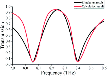 | ||
| Fig. 6 Simulated transmission spectrum (black line) and calculated transmission spectrum (red line) by the “two-particle” model. | ||
The separation between two BCs is a critical parameter that affects the EIT effect in the metamaterial. Therefore, the influence of separation (s) on the EIT window is also investigated, as shown in Fig. 7. Fig. 7 displays the simulated (solid lines) and fitted (dashed lines) transmission spectra for our EIT metamaterial with s varying from 1 μm to 3 μm. It is seen that as s increases, the EIT window becomes narrow, and its transmission peak declines. This is due to the fact that the interaction between scattered EM fields of two BCs becomes weaker with the increase in s. The fitting parameters are listed in Table 1. It can be found that as s changes from 1 μm to 3 μm, γ1 and γ2 values become larger, whereas the k value becomes smaller. In this case, the coupling between two BC resonators becomes weak; as a result, the EIT window becomes narrow, and its strength decreases. It is also noticed that when s = 1 μm, the resonance width of the EIT window is the widest, and its peak is the largest. Therefore, we demonstrate the EIT effect in our metamaterial through numerical simulation and the “two-particle” model, similar to previously reported observations.11,33–35
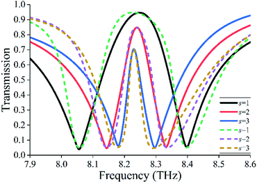 | ||
| Fig. 7 Simulated (solid lines) and fitted (dashed lines) transmission spectra for the proposed EIT metamaterial with s changing from 1 μm to 3 μm. | ||
| s (μm) | d (μm) | γ1 (THz) | γ2 (THz) | δ (THz) | k (THz) |
|---|---|---|---|---|---|
| 1 | 10 | 0.07 | 0.015 | 0.06 | 1.67 |
| 2 | 11 | 0.085 | 0.014 | 0.049 | 1.25 |
| 3 | 12 | 0.1 | 0.01 | 0.055 | 0.95 |
Generally, to achieve polarization-independent property, the structure of the metamaterial should possess characteristics of horizontal and vertical symmetries. This is because an arbitrarily polarized wave can be considered as a vector superposition of x-polarized and y-polarized waves.16 In previously reported studies, the symmetry of a structure is usually based on multiple rotations of the substructure such as four-fold and eight-fold rotational symmetry structures,3,15,16,21,36–40 whereas the symmetry of our structure originates from the structure itself. Owing to the symmetry of our structure, it is predicted that its transmission response is polarization-independent.
To verify polarization independence and angle insensitivity for our proposed structure, the transmission responses of our metamaterial for incident EM waves with different polarization angles (φ) are investigated, and the results are shown in Fig. 8. Here, φ is the angle between the polarization direction of the incident wave and x-axis. It can be seen that the transmission responses are almost invariant regardless of x-polarization (φ = 0°), 45°-polarization (φ = 45°), or y-polarization (φ = 90°), which means that the EIT window is unaffected by the direction of polarization for incident waves. In other words, the proposed metamaterial has good polarization-independent characteristic. The spectral responses of the proposed metamaterial for different incident angles (θ) are also investigated, as displayed in Fig. 9. Here, θ refers to the angle between the direction of incident wave and z-axis. It can be seen that the EIT window is almost stable for incident angles varying from 0° ≤ θ ≤ 30°. These polarization-independent and angle-insensitive properties mainly result from the symmetry and uniformity of the structure itself.
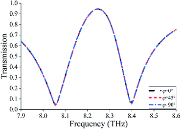 | ||
| Fig. 8 Simulated transmission spectra for the proposed EIT metamaterial with polarization angle φ changing from 0° to 90°. | ||
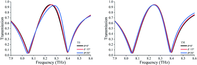 | ||
| Fig. 9 Simulated transmission spectra for the proposed EIT metamaterial with incident angle θ changing from 0° to 30°. | ||
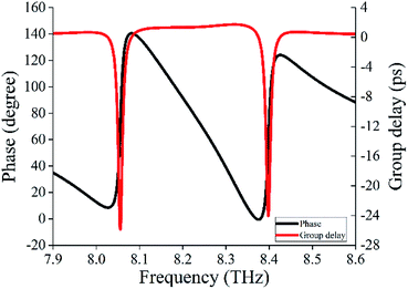
The EIT effect in metamaterials is always accompanied by steep phase dispersion, which leads to slow light effect.10,41 To confirm the slow light property in our structure, the group delay of metamaterial is extracted by the following formula:19,42
 | (4) |
4. Conclusion
In summary, a polarization-independent and angle-insensitive all-dielectric EIT metamaterial has been achieved in terahertz regimes. The EIT window is induced at around 8.25 THz with the transmittance peak of about 0.95. Numerical simulations have demonstrated that the EIT effect results from destructive couplings between Mie electric and magnetic resonances. By using the “two-particle” model, we have quantitatively described the EIT effect, and we have investigated its variations with different couplings between two BCs. The analytical results have indicated that there is relevance between the depths of two transmission dips and the loss of superradiant resonator. The frequency position of the transmission peak is mainly affected by detuning of resonance frequencies for the two resonators, and the width as well as peak intensity of EIT resonance is mainly dependent on the loss of the subradiant resonator and coupling (separation) between two resonators. In addition, we have also verified the polarization-independent and angle-insensitive properties for the EIT metamaterial. Finally, the group delay has been calculated to validate the slow light property in the EIT metamaterial. Such EIT metamaterial has features of polarization independence, incident angle insensitivity, and high transmittance (low loss). Thus, it may be applied in many areas such as low-loss slow light devices and bandpass filters.Conflicts of interest
There are no conflicts to declare.Acknowledgements
This work is supported by the National Natural Science Foundation of China (Grant No. 61501275), the China Postdoctoral Science Special Foundation (2018T110274), the China Postdoctoral Science Foundation (Grant No. 2017M611357), the Science Foundation Project of Heilongjiang Province of China (Grant No. QC2015073), the Postdoctoral Science Foundation of Heilongjiang Province of China (LBH-Z17045), the Young creative talents training plan of general universities of Heilongjiang Province of China (UNPYSCT-2017152), and the technology bureau of Qiqihar city of Heilongjiang Province of China (Grant No. GYGG-201511).Notes and references
- K.-J. Boller, A. Imamoglu and S. E. Harris, Observation of electromagnetically induced transparency, Phys. Rev. Lett., 1991, 66, 2593–2596 CrossRef PubMed.
- N. Papasimakis, V. A. Fedotov, N. I. Zheludev and S. L. Prosvirnin, A metamaterial analog of electromagnetically induced transparency, Phys. Rev. Lett., 2008, 101, 253903 CrossRef PubMed.
- S. Hu, D. Liu, H. Lin, J. Chen, Y. Y. Yi and H. L. Yang, Analogue of ultra-broadband and polarization-independent electromagnetically induced transparency using planar metamaterial, J. Appl. Phys., 2017, 121, 123103 CrossRef.
- S. Zhang, D. A. Genov, Y. Wang, M. Liu and X. Zhang, Plasmon-induced transparency in metamaterials, Phys. Rev. Lett., 2008, 101, 047401 CrossRef PubMed.
- P. Tassin, L. Zhang, T. Koschny, E. N. Economou and C. M. Soukoulis, Low-loss metamaterials based on classical electromagnetically induced transparency, Phys. Rev. Lett., 2009, 102, 053901 CrossRef PubMed.
- S.-Y. Chiam, R. Singh, C. Rockstuhl, F. Lederer, W. L. Zhang and A. A. Bettiol, Analogue of electromagnetically induced transparency in a terahertz metamaterial, Phys. Rev. B: Condens. Matter Mater. Phys., 2009, 80, 153103 CrossRef.
- Z. Y. Li, Y. F. Ma, R. Huang, R. Singh, J. Q. Gu, Z. Tian, J. G. Han and W. L. Zhang, Manipulating the plasmon-induced transparency in terahertz metamaterials, Opt. Express, 2011, 19, 8912–8919 CrossRef PubMed.
- H. Lu, X. Liu and D. Mao, Plasmonic analog of electromagnetically induced transparency in multi-nanoresonator-coupled waveguide systems, Phys. Rev. A: At., Mol., Opt. Phys., 2012, 85, 053803 CrossRef.
- R. W. Boyd and D. J. Gauthier, Photonics: transparency on an optical chip, Nature, 2006, 441, 701–702 CrossRef PubMed.
- N. Papasimakis, Y. H. Fu, V. A. Fedotov, S. L. Prosvirnin, D. P. Tsai and N. I. Zheludev, Metamaterial with polarization and direction insensitive resonant transmission response mimicking electromagnetically induced transparency, Appl. Phys. Lett., 2009, 94, 056613 CrossRef.
- X. J. He, Y. M. Huang, X. Y. Yang, L. Zhu, F. M. Wu and J. X. Jiang, Tunable electromagnetically induced transparency based on terahertz graphene metamaterial, RSC Adv., 2017, 7, 40321–40326 RSC.
- Y. R. Sun, H. Chen, X. J. Li and Z. Hong, Electromagnetically induced transparency in planar metamaterials based on guided mode resonance, Opt. Commun., 2017, 392, 142–146 CrossRef.
- S. Zhang, D. A. Genov, Y. Wang, M. Liu and X. Zhang, Plasmon-induced transparency in metamaterials, Phys. Rev. Lett., 2008, 101, 047401 CrossRef PubMed.
- Z. Vafapour and H. Alaei, Achieving a high Q-factor and tunable slow-light via classical electromagnetically induced transparency (Cl-EIT) in metamaterials, Plasmonics, 2016, 12, 1–10 Search PubMed.
- S. Mun, K. Lee, H. Yun and B. Lee, Polarization-independent plasmon-induced transparency in a symmetric metamaterial, IEEE Photonics Technol. Lett., 2016, 28, 2581–2584 Search PubMed.
- X. Q. Zhang, Q. Li, W. Cao, J. Q. Gu, R. Singh, Z. Tian, J. G. Han and W. L. Zhang, Polarization-independent plasmon-induced transparency in a fourfold symmetric terahertz metamaterial, IEEE J. Sel. Top. Quantum Electron., 2013, 19, 8400707 Search PubMed.
- C. Y. Chen, I. W. Un, N. H. Tai and T. J. Yen, Asymmetric coupling between subradiant and superradiant plasmonic resonances and its enhanced sensing performance, Opt. Express, 2009, 17, 15372 CrossRef PubMed.
- Y. F. Ma, Z. Y. Li, Y. M. Yang, R. Huang, R. Singh, S. Zhang, J. Q. Gu, Z. Tian, J. G. Han and W. L. Zhang, Plasmon-induced transparency in twisted Fano terahertz metamaterials, Opt. Mater. Express, 2011, 1, 391–399 CrossRef.
- Z. C. Wei, X. P. Li, N. F. Zhong, X. P. Tan, X. M. Zhang, H. Z. Liu, H. Y. Meng and R. S. Liang, Analogue electromagnetically induced transparency based on low-loss metamaterial and its application in nanosensor and slow-light device, Plasmonics, 2016, 12, 1–7 Search PubMed.
- C. H. Sui, B. X. Han, T. T. Lang, X. J. Li, X. F. Jing and Z. Hong, Electromagnetically induced transparency in an all-dielectric metamaterial-waveguide with large group index, IEEE Photonics J., 2017, 99, 1 Search PubMed.
- F. L. Zhang, Q. Zhao, J. Zhou and S. X. Wang, Polarization and incidence insensitive dielectric electromagnetically induced transparency metamaterial, Opt. Express, 2013, 21, 19675 CrossRef PubMed.
- F. L. Zhang, Q. Zhao, C. W. Lan, X. He, W. H. Zhang, J. Zhou and K. P. Qiu, Magnetically coupled electromagnetically induced transparency analogy of dielectric metamaterial, Appl. Phys. Lett., 2014, 104, 36 Search PubMed.
- J. Wang, Z. Xu, Z. H. Yu, X. Y. Wei, Y. M. Yang, J. F. Wang and S. B. Qu, Experimental realization of all-dielectric composite cubes/rods left-handed metamaterial, J. Appl. Phys., 2011, 109, 084918 CrossRef.
- Q. Zhao, J. Zhou, F. L. Zhang and D. Lippens, Mie resonance-based dielectric metamaterials, IEEE Photonics J., 2009, 12, 60–69 Search PubMed.
- J. Zhang, K. F. Macdonald and N. I. Zheludev, Near-infrared trapped mode magnetic resonance in an all-dielectric metamaterial, Opt. Express, 2013, 21, 26721 CrossRef PubMed.
- S. Hu, H. L. Yang, S. Han, X. J. Huang and B. X. Xiao, Tailoring dual-band electromagnetically induced transparency in planar metamaterials, J. Appl. Phys., 2015, 117, 4773 Search PubMed.
- P. Ding, J. He, J. Q. Wang, C. Z. Fan and E. Liang, Electromagnetically induced transparency in all-dielectric metamaterial-waveguide system, Appl. Opt., 2015, 54, 3708–3714 CrossRef.
- Z. P. Wang and B. L. Yu, Optical bistability via dual electromagnetically induced transparency in a coupled quantum-well nanostructure, J. Appl. Phys., 2013, 113, 113101–113106 CrossRef.
- N. Liu, L. Langguth, T. Weiss, J. Kästel, M. Fleischhauer, T. Pfau and H. Giessen, Plasmonic analogue of electromagnetically induced transparency at the Drude damping limit, Nat. Mater., 2009, 8, 758–762 CrossRef PubMed.
- F. Y. Meng, Q. Wu, D. Erni, K. Wu and J. Lee, Polarization-Independent Metamaterial Analog of Electromagnetically Induced Transparency for a Refractive-Index-Based Sensor, IEEE Trans. Microwave Theory Tech., 2012, 60, 3013–3022 Search PubMed.
- L. Zhu and L. Dong, Electromagnetically induced transparency with wide band in all-dielectric microstructure based on Mie resonances, J. Opt., 2014, 16, 125105 CrossRef.
- L. Zhu, F. Y. Meng, L. Dong, Q. Wu, B. J. Che, J. Gao, J. H. Fu, K. Zhang and G. H. Yang, Magnetic metamaterial analog of electromagnetically induced transparency and absorption, J. Appl. Phys., 2015, 117, 063901 CrossRef.
- C. Liu, P. Liu, C. Yang, Y. Lin and S. Zha, Dynamic electromagnetically induced transparency based on a metal-graphene hybrid metamaterial, Opt. Mater. Express, 2018, 8, 1132 CrossRef.
- D. C. Liang, H. F. Zhang, J. Q. Gu, Y. F. Li, Z. Tian, C. M. Ouyang, J. G. Han and W. L. Zhang, Plasmonic analogue of electromagnetically induced transparency in stereo metamaterials, IEEE J. Sel. Top. Quantum Electron., 2017, 23, 1–7 Search PubMed.
- S. Xiao, T. Wang, T. Liu, X. Yan, Z. Li and C. Xu, Active modulation of electromagnetically induced transparency analogue in terahertz hybrid metal-graphene metamaterials, Carbon, 2018, 126, 271–278 CrossRef.
- B. Zhu, Z. Wang, C. Huang, Y. Feng, J. Zhao and T. Jiang, Polarization insensitive metamaterial absorber with wide incident angle, Prog. Electromagn. Res., 2011, 115, 231–239 Search PubMed.
- X. Y. Duan, S. Q. Chen, H. F. Yang, H. Cheng, J. J. Li, W. W. Liu, C. Z. Gu and J. G. Tian, Polarization-insensitive and wide-angle plasmonically induced transparency by planar metamaterials, Appl. Phys. Lett., 2012, 101, 047401 Search PubMed.
- F. k. Dincer, M. Karaaslan, E. Unal, K. Delihacioglu and C. Sabah, Design of polarization and incident angle insensitive dual-band metamaterial absorber based on isotropic resonator, Prog. Electromagn. Res., 2014, 144, 123–132 CrossRef.
- J. X. Zhao, S. Han, H. Lin and H. L. Yang, Tailoring the multiple electrically resonant transparency through bi-layered metamaterial-induced coupling oscillators, J. Phys. D: Appl. Phys., 2015, 48, 455502 CrossRef.
- D. J. Lee, J. G. Hwang, D. Lim, T. Hara and S. Lim, Incident angle- and polarization-insensitive metamaterial absorber using circular sectors, Sci. Rep., 2016, 6, 27155 CrossRef PubMed.
- A. Yang, C. C. Yan, J. B. Tian, C. Wang, G. M. Li and D. H. Zhang, An analog of double electromagnetically induced transparency with extremely high group indexes, Chin. Opt. Lett., 2013, 11, 46–48 CrossRef.
- X. G. Yin, T. H. Feng, S. Yip, Z. X. Liang, A. Hui, J. C. Ho and J. Li, Tailoring electromagnetically induced transparency for terahertz metamaterials: From diatomic to triatomic structural molecules, Appl. Phys. Lett., 2013, 103, 021115 CrossRef.
| This journal is © The Royal Society of Chemistry 2018 |

