
 Open Access Article
 This Open Access Article is licensed under a Creative Commons Attribution-Non Commercial 3.0 Unported Licence
Ionic-liquid-assisted one-pot synthesis of Cu2O nanoparticles/multi-walled carbon nanotube nanocomposite for high-performance asymmetric supercapacitors†
Ying Lu,
Jian-Long Xu *,
Shan Ren,
Ya-Nan Zhong,
Xu Gao and
Sui-Dong Wang*
*,
Shan Ren,
Ya-Nan Zhong,
Xu Gao and
Sui-Dong Wang*
Institute of Functional Nano & Soft Materials (FUNSOM), Jiangsu Key Laboratory for Carbon-Based Functional Materials & Devices, Soochow University, Suzhou, Jiangsu 215123, P. R. China. E-mail: xujianlong@suda.edu.cn; wangsd@suda.edu.cn
First published on 1st June 2018
Abstract
Finding earth-abundant and high-performance electrode materials for supercapacitors is a demanding challenge in the energy storage field. Cuprous oxide (Cu2O) has attracted increasing attention due to its theoretically high specific capacitance, however, the development of Cu2O-based electrodes with superior capacitive performance is still challenging. We herein report a simple and effective ionic-liquid-assisted sputtering approach to synthesizing the Cu2O nanoparticles/multi-walled carbon nanotubes (Cu2O/MWCNTs) nanocomposite for high-performance asymmetric supercapacitors. The Cu2O/MWCNTs nanocomposite delivers a high specific capacitance of 357 F g−1, good rate capability and excellent capacitance retention of about 89% after 20![[thin space (1/6-em)]](https://www.rsc.org/images/entities/char_2009.gif) 000 cycles at a current density of 10 A g−1. The high performance is attributed to the uniform dispersion of small-sized Cu2O nanoparticles on conductive MWCNTs, which offers plenty of redox active sites and thus improve the electron transfer efficiency. Oxygen vacancies are further introduced into Cu2O by the NaBH4 treatment, providing the oxygen-deficient Cu2O/MWCNTs (r-Cu2O/MWCNTs) nanocomposite with significantly improved specific capacitance (790 F g−1) and cycling stability (∼93% after 20000 cycles). The assembled asymmetric supercapacitor based on the r-Cu2O/MWCNTs//activated carbon (AC) structure achieves a high energy density of 64.2 W h kg−1 at 825.3 W kg−1, and long cycling life. This work may form a foundation for the development of both high capacity and high energy density supercapacitors by showcasing the great potential of earth-abundant Cu-based electrode materials.
000 cycles at a current density of 10 A g−1. The high performance is attributed to the uniform dispersion of small-sized Cu2O nanoparticles on conductive MWCNTs, which offers plenty of redox active sites and thus improve the electron transfer efficiency. Oxygen vacancies are further introduced into Cu2O by the NaBH4 treatment, providing the oxygen-deficient Cu2O/MWCNTs (r-Cu2O/MWCNTs) nanocomposite with significantly improved specific capacitance (790 F g−1) and cycling stability (∼93% after 20000 cycles). The assembled asymmetric supercapacitor based on the r-Cu2O/MWCNTs//activated carbon (AC) structure achieves a high energy density of 64.2 W h kg−1 at 825.3 W kg−1, and long cycling life. This work may form a foundation for the development of both high capacity and high energy density supercapacitors by showcasing the great potential of earth-abundant Cu-based electrode materials.
Introduction
Nowadays, with great demand for renewable energy systems, supercapacitors have attracted immense attention as an important class of energy storage devices.1–4 Compared with batteries, supercapacitors exhibit significantly high power density and long cycling life, and are expected to have more practical applications if their energy density can be further boosted to a higher level.5,6 This motivation has driven extensive research efforts to enhance the energy density and overall performance of supercapacitors in order to broaden their application spectrum.5–8 Rational design and synthesis of high-performance and low-cost electrode materials are one of the keys to realize the target. In general, based on the charge storage mechanism, supercapacitors can be classified into electric double-layer capacitors (EDLCs) and pseudocapacitors. In contrast to EDLCs in which capacitance originates from the electrode/electrolyte interface charge accumulation effect, pseudocapacitors can offer much larger specific capacitance due to the fast and reversible redox reactions on the electrodes and thus show higher energy density.9,10 Transition metal oxides often possess higher specific capacitance and electrochemical cycling stability than most conductive polymers, and are preferred as electrode materials for supercapacitors.11–14 Among various pseudocapacitive oxides, nanostructured Cu oxides and hydroxides are promising ones owing to their high specific capacitance, elemental abundance and friendliness to environment.10,15–18 Especially, cuprous oxide (Cu2O) stands out because of its theoretical specific capacitance as large as about 2248 F g−1, predicting the potential application of Cu2O as supercapacitor electrodes.19 Moreover, Cu2O often exhibits better cycling stability than CuO in alkaline electrolyte.20 For example, Chen et al. synthesized the Cu2O microspheres with a specific capacitance of 144 F g−1 at a current density of 0.1 A g−1,21 and Wang et al. prepared the Cu2O/CuO/rGO nanocomposite with a specific capacitance of 173.4 F g−1 at a current density of 1 A g−1 and high cycling stability.20 Recently, Zhang et al. also reported the nanocomposite of rose-rock-shaped Cu2O anchored graphene composite by a solvothermal method with a favorable electrochemical capacitance of 416 F g−1 at 1 A g−1.22Despite the notable progress of Cu2O-based supercapacitor electrodes, how to achieve Cu2O-based electrodes simultaneously with large specific capacitance, high cycling stability and high energy density by a simple method still remains challenging. The effective strategy lies in increasing the electronic conductivity, improving the active site availability for pseudocapacitive reactions, and providing short electron transport pathways for fast electrode kinetics.9,10,23 Hybridizing one dimensional (1D) or two dimensional (2D) conductive carbon materials with oxide nanoparticles is an effective way.12,20,24–27 In such nanocomposites, conductive carbon nanosupports enable fast electron transport and facilitate the kinetics of electrochemical reactions, while nano-sized metal oxides can increase the effective surface area and shorten the ion/electron diffusion paths, thus leading to high pseudocapacitive performance. Till now, most reported synthesis approaches of Cu2O nanocomposites are wet-chemical processes, which are often complex and require a high-temperature treatment process.17,20–22,28–30 During the processes, the precise control of the Cu valence is challenging, and it is inevitable that the employment of additive agents or stabilizers may damage the carbon material surface or induce some adverse functional groups. Therefore, attempts toward simple synthesis of small-sized and bare Cu2O nanoparticles decorated on carbon nanosupports with high electrochemical performance are still needed.
We have recently developed an alternative physical way to prepare metal nanoparticles/carbon hybrids by directly sputtering metal onto room-temperature ionic liquid (RTIL).31,32 This process is a one-step and environmental-friendly approach totally free of additive agent, stabilizer and by-product. In this report, utilizing the RTIL-assisted method, Cu2O nanoparticles anchored on multi-walled carbon nanotubes (abbreviated as Cu2O/MWCNTs) with small size and high uniformity are obtained by directly sputtering metal Cu into a typical RTIL, 1-butyl-3-methylimidazoliumtetrafluoro borate ([BMIm][BF4]). The prepared Cu2O/MWCNTs nanocomposite possesses excellent electrochemical properties including high specific capacitance, high cycling stability and good rate capability. Furthermore, oxygen vacancies are introduced into the Cu2O/MWCNTs nanocomposite by the NaBH4 treatment, which further enhances the specific capacitance and rate capability of the nanocomposite (abbreviated as r-Cu2O/MWCNTs). An asymmetric supercapacitor using the r-Cu2O/MWCNTs nanocomposite as positive electrode and active carbon (AC) as negative electrode is assembled, which features a high energy density of 64.2 W h kg−1 at a power density of 855.3 W kg−1, as well as high cycling stability with capacitance retention of 93% after 20000 cycling times. The results indicate the great potential of the r-Cu2O/MWCNTs nanocomposite as positive electrodes for high-performance supercapacitors.
Experimental
Materials
[BMIm][BF4] (purity > 99%) was purchased from Shanghai Cheng-Jie Chemical. Purified MWCNTs with –OH surface functional groups were purchased from Nanjing XFNANO Materials Tech. NaBH4, KOH, Nafion solution and ethanol were purchased from Sigma Aldrich. Deionized water (18 MΩ cm) was produced with a Milli-Q system. All chemicals were used as received without further purification.Nanocomposite preparation
The Cu2O/MWCNTs nanocomposite was prepared by the RTILs-assisted sputtering process, as illustrated in Scheme 1. Firstly, 3 mg MWCNTs was fully dispersed into 1.5 mL [BMIm][BF4] by ultrasonication for 10 min to obtain a black suspension. Then, the suspension was placed in a clean stainless steel pot, and Cu was sputtered into the suspension for 800 s with a desktop sputtering system (Quorum Technologies). The working pressure and deposition rate were kept at 0.01 mbar and 0.2 Å s−1, respectively. Thirdly, the sample after sputtering was stirred and heated at 250 °C for 2 h and then cooled down to room temperature naturally. Finally, the Cu2O/MWCNTs nanocomposite was separated from [BMIm][BF4] by high-speed centrifugation, followed by multiple washing in acetone and deionized water. The final product was a dry black powder and employed as the supercapacitor electrode material. | ||
| Scheme 1 Schematic illustration of preparation process of Cu2O/MWCNTs nanocomposite by RTIL-assisted Cu sputtering. | ||
Material characterization
The morphological characteristics of the Cu2O/MWCNTs nanocomposite were characterized using high-resolution transmission electron microscopy (HRTEM, FEI Tecnai G2) and high-angle annular dark field scanning TEM (HAADF-STEM). The crystalline structures of pristine MWCNTs and the Cu2O/MWCNTs nanocomposite were measured by X-ray diffraction (XRD, PANalytical Empyrean) with Cu Kα radiation. The electronic structures of the nanocomposite were studied by X-ray photoelectron spectroscopy (XPS, Kratos Axis Ultra DLD) and X-ray absorption spectroscopy (XAS) at the Taiwan Light Source (TLS).Electrochemical measurements
For the electrode tests, the working electrodes were prepared as follows: firstly, the active material (80 wt%) and carbon black (10 wt%) were mixed to form a homogeneous powder. Then, Nafion solution (10 wt%) and a few drops of ethanol were added to get a slurry. After that, the slurry was coated onto a Ni foam (1 cm × 1 cm). Finally, the electrodes were dried in air at 60 °C for 12 h. The mass loading of the active material on Ni foam is 1 mg cm−2.The electrochemical measurements were carried out with an electrochemical workstation (CHI660D, Shanghai, China) in a 6 M KOH aqueous electrolyte solution using a three-electrode system, with a Pt wire and a saturated calomel electrode (SCE) as the counter and reference electrodes, respectively. The cyclic voltammetry (CV) and galvanostatic charge/discharge (GCD) measurements were performed in the potential range from 0 to 0.4 V versus SCE. The electrochemical impedance spectroscopy (EIS) test was carried out in the frequency range from 0.01 Hz to 100 kHz. The mass normalized specific capacitance (Cm), specific energy density (Em) and power density (Pm) are calculated from the CV or GCD curves according to the following equations:
 | (1) |
 | (2) |
 | (3) |
 | (4) |
The asymmetric supercapacitor was assembled using the r-Cu2O/MWCNTs nanocomposite as positive electrode and commercial activated carbon (AC) as negative electrode, and performed in a two-electrode cell in 6 M KOH aqueous solution. The electrochemical parameters of the asymmetric supercapacitor are calculated based on the total mass of the coated active material.
Results and discussions
Morphological and structural characterization
The TEM and HRTEM images of the Cu2O/MWCNTs nanocomposite are shown in Fig. 1. As seen in Fig. 1a and b, the 1D structure of MWCNTs is well kept after the decoration of Cu2O nanoparticles, which have an average diameter of about 9 nm and are uniformly dispersed on the MWCNTs surface. In the nanocomposite, the heavy loading of Cu2O nanoparticles on MWCNTs can prevent the MWCNTs from stacking after drying, resulting in the abundant active surface area that is beneficial for supercapacitors. The HRTEM image in Fig. 1c clearly shows the lattice fringes with an interplanar spacing of 0.24 nm matching with the (111) planes of Cu2O. Moreover, HAADF-STEM is utilized to map the elemental spatial distribution in the Cu2O/MWCNTs nanocomposite. Fig. 1d shows the mapping images, which indicate the uniform distribution of nanoparticles on the MWCNT surface. The overlapping of the spatial distribution for Cu and O suggests the presence of Cu2O.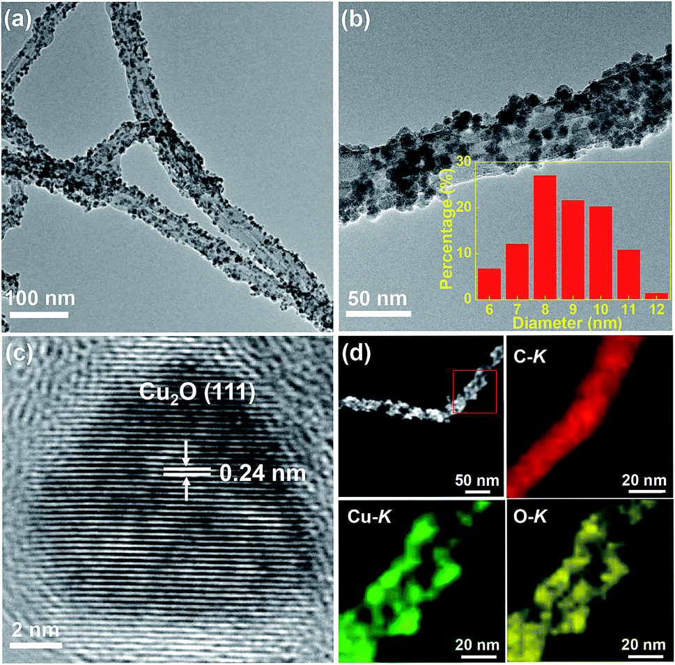 | ||
| Fig. 1 (a) and (b) TEM images of Cu2O/MWCNTs nanocomposite, inset in (b) presents diameter distribution of the Cu2O nanoparticles. (c) HRTEM image of a typical Cu2O nanoparticle on MWCNTs. (d) HAADF-STEM images of Cu2O/MWCNTs nanocomposite. | ||
The crystalline structure of the Cu2O nanoparticles is probed by the XRD patterns as illustrated in Fig. 2a. All the diffraction peaks can be assigned to MWCNTs and Cu2O. Except one peak (2θ = 26°) arising from the (002) plane of MWCNTs, there are four diffraction peaks at 2θ of 36.5°, 42.3°, 61.5° and 73.5° for the Cu2O/MWCNTs composite, corresponding to the (111), (200), (220) and (311) planes of crystalline Cu2O, respectively (JCPDS no. 78-2076).33,34 The unshifted MWCNTs (002) peak indicates that the Cu2O decoration does not affect the MWCNTs structure. Besides, Raman spectroscopy was also used to characterize pristine MWCNTs and the Cu2O/MWCNTs nanocomposite, as shown in Fig. 2b. The characteristic D, G and 2D peaks are observed in the Raman spectra, and there is no obvious peak shift after the loading of Cu2O nanoparticles. The G peak originates from the vibrational modes of the graphitic structure, while the D peak is associated with structural defects.35 The intensity ratio of the D peak to the G one (ID/IG) is 1.35 for the Cu2O/MWCNTs nanocomposite, similar to that for pristine MWCNTs (1.44). It implies that the Cu2O decoration does not induce additional defects in MWCNTs.
 | ||
| Fig. 2 Spectroscopic characterization of Cu2O/MWCNTs nanocomposite. (a) XRD patterns and (b) Raman spectra of Cu2O/MWCNTs nanocomposite compared with pristine MWCNTs. (c) XPS Cu 2p spectrum and (d) XAS Cu L-edge spectrum of Cu2O/MWCNTs nanocomposite. | ||
Fig. 2c shows the XPS Cu 2p spectrum of the Cu2O/MWCNTs nanocomposite. The peaks at 932.4 and 952.2 eV, corresponding to Cu 2p3/2 and Cu 2p1/2 of Cu+ respectively, confirming the existence of Cu2O in the nanocomposite.36 On the other hand, two broad peaks at 935.3 and 955.1 eV can be assigned to Cu 2p3/2 and Cu 2p1/2 of Cu2+ respectively,37 which suggest the presence of amorphous CuO on the Cu2O nanoparticles presumably due to the surface oxidation. Meanwhile, no metallic Cu signal can be observed in the XPS spectrum. Further information on the electronic structure of the Cu2O/MWCNTs nanocomposite is obtained from the XAS measurements.
Fig. 2d presents the XAS Cu L-edge spectrum of the nanocomposite, in which the Cu absorption edges around 930.5 and 933.5 eV are observed. The XAS data match with the reported L-edges of CuO and Cu2O,38 indicating the oxidized states of Cu in good agreement with the XPS results.
Electrochemical performance
The electrochemical properties of the Cu2O/MWCNTs electrode are firstly evaluated by CV characterization with a standard three-electrode configuration. Fig. 3a shows the CV curves of the Cu2O/MWCNTs electrode in a potential window of 0–0.4 V versus SCE at different scan rates. The CV curve shapes are quite different from the ideal rectangular shape dominated by the electric double-layer capacitance, suggesting that the pseudocapacitance of Cu2O is dominant in the present case. A couple of strong anodic and cathodic redox peaks are observed in the CV curves, which can be attributed to the faradaic redox reactions of the Cu+/Cu2+ transition. The shape of CV curves does not show significant change with the increase of scan rate, indicating the excellent electric conductivity of Cu2O/MWCNTs composite. The conductivity of the Cu2O/MWCNTs electrode was measured by a constant current four-electrode method,39 and the calculated conductivity of the electrode is 585 S cm−1, confirming the high conductivity of the Cu2O/MWCNTs electrode. In addition, the current response increases when the scan rate increases, accompanied by a shift of the redox peaks at high scan rates. These features indicate the good rate performance and further confirm the pseudocapacitive characteristics of the Cu2O/MWCNTs nanocomposite. | ||
| Fig. 3 Electrochemical characterization of Cu2O/MWCNTs nanocomposite electrode in aqueous KOH electrolyte: (a) CV curves at various scan rates ranging from 5 to 200 mV s−1. (b) GCD curves at various current densities ranging from 1 to 50 A g−1. (c) Specific capacitance versus scan rate of pristine MWCNTs and Cu2O/MWCNTs nanocomposite calculated from the GCD curves. (d) Imaginary impedance Z′′ versus real impedance Z′ in the frequency range from 0.01 Hz to 100 kHz, where inset shows a magnified section in the high frequency range. (e) Cycling stability performance of Cu2O/MWCNTs nanocomposite electrode, where insets show GCD curves recorded at different cycling stages. | ||
Moreover, except for CV characterizations, the galvanostatic charge–discharge (GCD) curves at different current densities ranging from 1 to 50 A g−1 in a potential range of 0–0.4 V (versus SCE) are also characterized, as shown in Fig. 3b. Obviously, the nonlinear GCD curves verify the deduction from the CV results, i.e., the charge storage in the Cu2O/MWCNTs nanocomposite is dominated by the faradaic redox reactions of Cu+/Cu2+ transition. As calculated from Fig. 3b based on eqn (2), the Cu2O/MWCNTs nanocomposite exhibits a large specific capacitance of 357 F g−1 at 1 A g−1, better than previously reported Cu-based electrode materials.12,15,20,21,28 As a comparison, the GCD curves of pristine MWCNTs are shown in Fig. S1a.† Fig. 3c shows the dependence of specific capacitance as a function of the charge/discharge current density for pristine MWCNTs and the Cu2O/MWCNTs nanocomposite. Apparently, the specific capacitances of pristine MWCNTs are much smaller than those of the nanocomposite, demonstrating the major contribution of Cu2O on the large specific capacitance. The Cu2O/MWCNTs nanocomposite remains excellent electrochemical performance at high charge/discharge rates, e.g., the specific capacitance at 50 A g−1 still has 36% of that at 1 A g−1. It demonstrates the good rate capability of the Cu2O/MWCNTs nanocomposite. The frequency response of the Cu2O/MWCNTs nanocomposite in a frequency range from 0.01 Hz to 100 kHz with an amplitude of 5 mV at an open-circuit potential is also examined by the EIS measurements, as depicted in Fig. 3d. The Nyquist plot shows a nearly straight line especially in the low frequency range, revealing an ideal capacitive behavior of the nanocomposite.40 Inset in Fig. 3d shows a magnified section of the Nyquist plot in the high frequency range, from which the equivalent series resistance (Rs) of the nanocomposite is extracted to be only 0.43 Ω. The low Rs value shows excellent ionic responses in the high-frequency range and proves the high conductivity of nanocomposite, which contributes to the negligible voltage drop in the GCD curves. Remarkably, the Cu2O/MWCNTs nanocomposite electrode exhibits excellent cycling stability at 10 A g−1 in a KOH electrolyte solution (Fig. 3e). The specific capacitance of the Cu2O/MWCNTs nanocomposite electrode can retain about 89% of the initial value after 20000 charge/discharge cycles. Insets in Fig. 3e show the GCD data of the first five cycles, and of the five cycles after 10000 and 20000 charge/discharge cycles, respectively. No significant change is observed in these GCD curves, and thus the pseudocapacitive performance is highly stable. The superior performance of the Cu2O/MWCNTs nanocomposite including large specific capacitance, good reversibility, high cycling stability, etc. may be ascribed to the synergistic effects between MWCNTs and the Cu2O nanoparticles: (1) MWCNTs can not only provide a steady loading of Cu2O nanoparticles with high dispersion, but also avoid serious agglomeration and volume variation of the Cu2O nanoparticles during the cycling process.41 (2) The multiplexed and highly conductive pathways provided by MWCNTs ensure the high electrical conductivity of the nanocomposite, and accordingly improve the charge transport and transfer efficiency. (3) The small-sized Cu2O nanoparticles stabilized on MWCNTs offer a large number of redox active sites to facilitate the redox reactions, which is the key to achieve the large specific capacitance. Moreover, the small size of Cu2O nanoparticles can shorten the charge transfer paths between Cu2O and MWCNTs and thus promoting the electron transport efficiency, leading to the excellent rate capability.9,42,43
In order to further improve the specific capacitance of the Cu2O/MWCNTs nanocomposite electrode, a reduction treatment in NaBH4 solution is carried out. Upon the reduction treatment, oxygen vacancies can be introduced into the Cu2O nanoparticles to form the r-Cu2O/MWCNTs nanocomposite, evidenced by the O 1s XPS spectra of Cu2O/MWCNTs before and after NaBH4 treatment (Fig. S2†). Notably, both O 1s curves are asymmetric and can be decomposed into four components, lattice oxygen species of Cu2O (∼530.4 eV for O2− in Cu2O), oxygen vacancies (∼531.3 eV), hydroxyl groups or the surface-adsorbed oxygen (∼531.8 eV for –OH and O2) and the adsorbed molecular water (∼532.5 eV for H2O).44–46 The ratio of various oxygen species estimated from the relative area of the fitted subpeaks is listed in Table S1.† It is clearly seen that the oxygen vacancy content in r-Cu2O/MWCNTs (43.9%) is higher than that in Cu2O/MWCNTs (20.7%), confirming the introduction of oxygen vacancies by NaBH4 treatment. Fig. 4a shows the CV curves of the r-Cu2O/MWCNTs nanocomposite measured under the same conditions for the Cu2O–MWCNTs one, and the calculated capacitance values are given in Fig. 4b. It is clear that the specific capacitance of the nanocomposite is greatly increased after the reduction treatment. As a comparison, the specific capacitances at a scan rate of 5 mV s−1 are 790 F g−1, 400 F g−1 and 244 F g−1 for the r-Cu2O/MWCNTs, Cu2O/MWCNTs nanocomposites and pristine MWCNTs (Fig. S1b†), respectively. The performance improvement is attributed to the generated oxygen vacancies in the r-Cu2O nanoparticles after the reduction treatment, which can offer more active sites, higher local conductivity and thus faster charge transfer.47 Fig. 4c depicts the GCD curves of the r-Cu2O/MWCNTs nanocomposite electrode at different current densities, and the corresponding Nyquist plots are shown in Fig. 4d. After the reduction treatment, the r-Cu2O/MWCNTs nanocomposite electrode exhibits much longer discharge time and thus much higher specific capacity value. Moreover, Rs of the r-Cu2O/MWCNTs nanocomposite is decreased to be 0.38 Ω compared with that of the Cu2O/MWCNTs one (0.43 Ω), providing more efficient pathways for charge transport in the electrode. The cycling stability of the r-Cu2O/MWCNTs nanocomposite is also investigated, as shown in Fig. 4e. After 20000 charge/discharge cycles at a high current density of 10 A g−1, the specific capacitance (309 F g−1) of the r-Cu2O/MWCNTs nanocomposite retains about 93% of the initial value (334 F g−1), demonstrating its high cycling stability and promise for applications in energy storage devices. It is worthy noting that the cycling stability is improved after the NaBH4 reduction treatment, which is consistent with the cases of other oxides such as Bi2O3, MoO3, etc.47,48
 | ||
| Fig. 4 Electrochemical characterization of r-Cu2O/MWCNTs electrode in aqueous KOH electrolyte: (a) CV curves at various scan rates ranging from 5 to 200 mV s−1. (b) Specific capacitance versus scan rate of pristine MWCNTs, Cu2O/MWCNTs and r-Cu2O/MWCNTs nanocomposites calculated from the CV curves. (c) GCD curves at various current densities ranging from 2 to 50 A g−1. (d) Imaginary impedance Z′′ versus real impedance Z′ in a frequency range from 0.01 Hz to 100 kHz, where inset shows a magnified section at low impedance. (e) Cycling stability performance of r-Cu2O/MWCNTs nanocomposite electrode, where insets show GCD curves recorded at different cycling stages. | ||
By adopting the r-Cu2O/MWCNTs nanocomposite and AC as positive and negative electrodes, respectively, a high-performance asymmetric supercapacitor is constructed and performed in aqueous solution of 6 M KOH. As shown in Fig. 5a, the r-Cu2O/MWCNTs nanocomposite electrode shows a stable potential window of 0–0.4 V, while the AC electrode exhibits stable operation in the range from −1.0 to 0 V, and thus this electrode configuration could extend the operation voltage window to 1.4 V. Fig. 5b depicts the CV curves of the asymmetric supercapacitor with a large operation window of 1.4 V at various scan rates. The pseudocapacitance shape of the CV curves does not change with increasing the scan rate, and the redox peaks are still present at high scan rate of 200 mV s−1, indicating the high rate capability and good reversibility of the asymmetric supercapacitor. Based on the total masses of active materials of the two electrodes, the calculated capacitances of the device were calculated as can be seen in Fig. S3.† The capacitance of the asymmetric supercapacitor device reaches 235.8 F g−1 at 5 mV s−1 and 94.3 F g−1 at 100 mV s−1, indicating the high rate performances of the device. The GCD curves of the asymmetric supercapacitor at different current densities ranging from 0.5 to 20 A g−1 are also measured and shown in Fig. 5c, and their nonlinear profile is consistent with the CV curves and indicates the dominant contribution of pseudocapacitance. The Rs value of the device is derived to be 0.55 Ω from the EIS results (Fig. S4†), which is quite small for asymmetric pseudocapacitors. In addition, the electrochemical stability of the asymmetric supercapacitor is evaluated by the repeated GCD cycling tests at a current density of 10 A g−1, as shown in Fig. 5d. The device can maintain over 93% of the initial capacitance value even after 20000 charge/discharge cycles at 10 A g−1, and it should benefit from the excellent electrochemical stability of the r-Cu2O/MWCNTs electrode, as confirmed above.
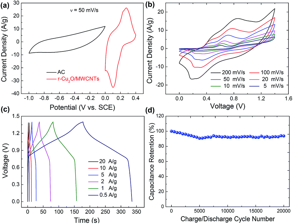 | ||
| Fig. 5 Electrochemical characterization of a r-Cu2O/MWCNTs//AC asymmetric supercapacitor: (a) CV curves of r-Cu2O/MWCNTs nanocomposite and AC electrodes at a scan rate of 50 mV s−1. (b) CV curves of the device at various scan rates ranging from 5 to 200 mV s−1. (c) GCD curves of the device at various current densities ranging from 0.5 to 20 A g−1. (d) Cycling stability performance of the device. | ||
To evaluate its operational performance/efficiency characteristics of the ASC device in practical applications, the power and energy density at different current densities are calculated according to eqn (3) and (4). Fig. 6 shows the Ragone plot to compare the energy density versus power density performance of the present asymmetric supercapacitor with the reported state-of-the-art pseudocapacitive asymmetric supercapacitors. The present device possesses a high energy density of 64.2 W h kg−1 with high power density of 825.3 W kg−1. Furthermore, the maximal power density can reach 10.04 kW kg−1 with energy density as high as 19.5 W h kg−1, demonstrating the outstanding rate capability of the present device. Therefore, the performance of the asymmetric supercapacitor herein is superior to many previously reported oxide-based asymmetric supercapacitors such as CuO//AC,10 Cu2O@Cu//AC,17 MnCo2O4@Ni(OH)2//AC,49 MnO2/graphene//VOS@C,50 CuO@MnO2//AG,51 where VOS and AG refer to the sulfur-doped VOx and activated graphene, respectively. The present device could be further improved by enlarging its operation voltage window, e.g., using ionic liquid electrolytes or further optimizing the electrochemical performance of both positive and negative electrodes.
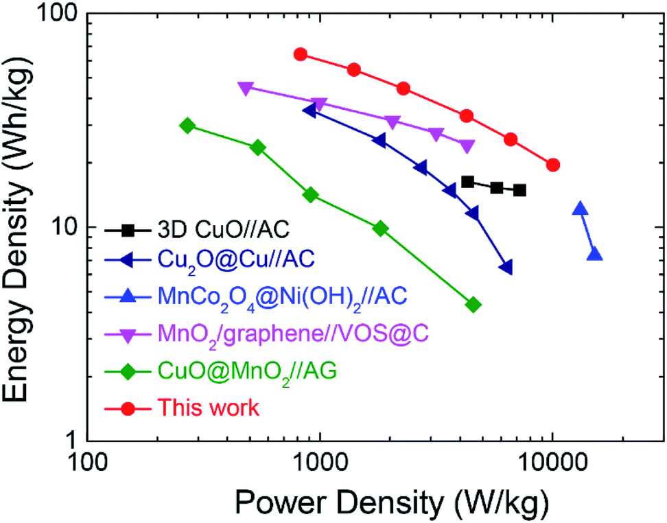 | ||
| Fig. 6 Ragone plots of present r-Cu2O/MWCNTs//AC asymmetric supercapacitor and reported oxide-based asymmetric supercapacitors for comparison. | ||
Conclusions
In conclusion, the oxygen-deficient r-Cu2O/MWCNTs nanocomposite for high-performance asymmetric supercapacitors is designed and successfully synthesized by a simple RTIL-assisted sputtering approach and a subsequent reduction treatment. The synthesizing process is one-pot, environmental-friendly, and free of additive agent, stabilizer and byproduct. The as-prepared Cu2O/MWCNTs nanocomposite delivers high specific capacitance of 357 F g−1, good rate capability and capacitance retention of 89% after 20000 cycles at 10 A g−1. The high performance results from the uniform dispersion of small-sized Cu2O nanoparticles on conductive MWCNTs, which provides plenty of redox active sites and facilitates charge transfer and electrolyte diffusion. After the reduction treatment in NaBH4 solution, oxygen vacancies are introduced into Cu2O and induce richer active sites and faster charge transfer, resulting in the oxygen-deficient r-Cu2O/MWCNTs nanocomposite with greatly improved specific capacitance (790 F g−1) and cycling stability (93% after 20000 cycles). Furthermore, the r-Cu2O/MWCNTs//AC asymmetric supercapacitor is fabricated, which shows high energy density of 64.2 W h kg−1 at 825.3 W kg−1 and long cycling life. The present RTIL-assisted synthesis strategy is simple and effective, and can be extended to synthesize other oxide-based supercapacitor electrode materials.
Conflicts of interest
There are no conflicts to declare.Acknowledgements
This work was supported by the National Natural Science Foundation of China (No. 61675143, 61705152, 61505132, 11661131002), the Natural Science Foundation of Jiangsu Province (No. BK20160328), the Collaborative Innovation Center of Suzhou Nano Science & Technology, and the Priority Academic Program Development of Jiangsu Higher Education Institutions.Notes and references
- P. Simon, Y. Gogotsi and B. Dunn, Science, 2014, 343, 1210 CrossRef PubMed.
- W. Li, J. Liu and D. Y. Zhao, Nat. Rev. Mater., 2016, 23, 16023 CrossRef.
- Y. H. Liu, J. L. Xu, X. Gao, Y. L. Sun, J. J. Lv, S. Shen, L. S. Chen and S. D. Wang, Energy Environ. Sci., 2017, 10, 2534 Search PubMed.
- W. Liu, M. S. Song, B. Kong and Y. Cui, Adv. Mater., 2017, 29, 1603436 CrossRef PubMed.
- H. Xiao, Z. S. Wu, L. Chen, F. Zhou, S. Zheng, W. C. Ren, H. M. Cheng and X. H. Bao, ACS Nano, 2017, 11, 7284 CrossRef PubMed.
- B. G. Choi, M. Yang, W. H. Hong, J. W. Choi and Y. S. Huh, ACS Nano, 2012, 6, 4020 CrossRef PubMed.
- W. Wang, W. Y. Liu, Y. X. Zeng, Y. Han, M. H. Yu, X. H. Lu and Y. X. Tong, Adv. Mater., 2015, 6, 3572 CrossRef PubMed.
- Q. C. Zhang, X. N. Wang, Z. H. Pan, J. Sun, J. X. Zhao, J. Zhang, C. X. Zhang, L. Tang, J. Luo, B. Song, Z. X. Zhang, W. B. Lu, Q. W. Li, Y. G. Zhang and Y. G. Yao, Nano Lett., 2017, 17, 2719 CrossRef PubMed.
- L. Liu, J. W. Lang, P. Zhang, B. Hu and X. B. Yan, ACS Appl. Mater. Interfaces, 2016, 8, 9335 Search PubMed.
- S. E. Moosavifard, M. F. El-Kady, M. S. Rahmanifar, R. B. Kaner and M. F. Mousavi, ACS Appl. Mater. Interfaces, 2015, 7, 4851 Search PubMed.
- B. Yao, L. Huang, J. Zhang, X. Gao, J. B. Wu, Y. L. Cheng, X. Xiao, B. Wang, Y. Li and J. Zhou, Adv. Mater., 2016, 28, 6353 CrossRef PubMed.
- A. Pendashteh, M. F. Mousavi and M. S. Rahmanifar, Electrochim. Acta, 2013, 88, 347 CrossRef.
- L. B. Dong, C. J. Xu, Y. Li, Z. H. Huang, F. Y. Kang, Q. H. Yang and X. Zhao, J. Mater. Chem. A, 2016, 4, 4659 Search PubMed.
- P. P. Shi, L. Li, L. Hua, Q. Q. Qian, P. F. Wang, J. Y. Zhou, G. Z. Sun and W. Huang, ACS Nano, 2017, 11, 444 CrossRef PubMed.
- X. J. Zhang, W. H. Shi, J. X. Zhu, D. J. Kharistal, W. Y. Zhao, B. S. Lalia, H. H. Hng and Q. Y. Yan, ACS Nano, 2011, 5, 2013 CrossRef PubMed.
- M. J. Deng, C. C. Wang, P. J. Ho, C. M. Lin, J. M. Chen and K. T. Lu, J. Mater. Chem. A, 2014, 2, 12857 Search PubMed.
- C. Q. Dong, Y. Wang, J. L. Xu, G. H. Cheng, W. F. Yang, T. Y. Kou, Z. H. Zhang and Y. Ding, J. Mater. Chem. A, 2014, 2, 18229 Search PubMed.
- J. Z. Chen, J. L. Xu, S. Zhou, N. Zhao and C. P. Wong, J. Mater. Chem. A, 2015, 3, 17385 Search PubMed.
- B. Vidhyadharan, I. I. Misnon, R. A. Aziz, K. P. Padmasree, M. M. Yusoff and R. Jose, J. Mater. Chem. A, 2014, 2, 6578–6588 Search PubMed.
- K. Wang, X. M. Dong, C. J. Zhao, X. Z. Qian and Y. L. Xu, Electrochim. Acta, 2015, 152, 433 CrossRef.
- L. Chen, Y. Zhang, P. L. Zhu, F. R. Zhou, W. J. Zeng, D. Q. D. Lu, R. Sun and C. P. Wong, Sci. Rep., 2015, 5, 9672 CrossRef PubMed.
- W. Zhang, Z. X. Yin, A. Chun, J. Yoo, G. W. Diao, Y. S. Kim and Y. Z. Piao, J. Power Sources, 2016, 318, 66 CrossRef.
- D. Cai, D. Wang, B. Liu, L. Wang, Y. Liu, H. Li, Y. Wang, Q. Li and T. Wang, ACS Appl. Mater. Interfaces, 2014, 6, 5050 Search PubMed.
- R. Raccichini, A. Varzi, S. Passerini and B. Scrosati, Nat. Mater., 2015, 14, 271 CrossRef PubMed.
- Q. Y. Liao, N. Li, S. X. Jin, G. W. Yang and C. X. Wang, ACS Nano, 2015, 9, 5310 CrossRef PubMed.
- F. Zhang, T. F. Zhang, X. Yang, L. Zhang, K. Leng, Y. Huang and Y. S. Chen, Energy Environ. Sci., 2013, 6, 1623 Search PubMed.
- J. Q. Liu, M. B. Zheng, X. Q. Shi, H. B. Zeng and H. Xia, Adv. Funct. Mater., 2016, 26, 919 CrossRef.
- B. J. Li, H. Q. Cao, G. Yin, Y. X. Lu and J. F. Yin, J. Mater. Chem., 2011, 21, 10645 RSC.
- M. J. Deng, C. Z. Song, P. J. Ho, C. C. Wang, J. M. Chen and K. T. Lu, Phys. Chem. Chem. Phys., 2013, 15, 7479 RSC.
- P. P. Xu, J. J. Liu, T. Liu, K. Ye, K. Cheng, J. L. Yin, D. X. Cao, G. L. Wang and Q. Li, RSC Adv., 2016, 6, 28270 RSC.
- C. H. Liu, X. Q. Chen, Y. F. Hu, T. K. Sham, Q. J. Sun, J. B. Chang, X. Gao, X. H. Sun and S. D. Wang, ACS Appl. Mater. Interfaces, 2013, 5, 5072 Search PubMed.
- C. H. Liu, J. Liu, Y. Y. Zhou, X. L. Cai, Y. Lu, X. Gao and S. D. Wang, Carbon, 2015, 94, 295 CrossRef.
- Joint Committee on Powder Diffraction Standards, JCPDS International Center for Diffraction Data, JCPDS no. 78-2076, Pennsylvania, USA, 1991.
- S. F. Zheng, J. S. Hu, L. S. Zhong, L. J. Wan, Y. Lu and W. G. Song, J. Phys. Chem. C, 2007, 111, 11174 Search PubMed.
- X. H. Xia, D. L. Chao, Y. Q. Zhang, J. Y. Zhan, Y. Zhong, X. L. Wang, Y. D. Wang, Z. X. Shen, J. P. Tu and H. J. Fan, Small, 2016, 12, 3048 CrossRef PubMed.
- D. W. Kim, K. Y. Rhee and S. J. Park, J. Alloys Compd., 2012, 530, 6 CrossRef.
- M. Yin, C. K. Wu, Y. Lou, C. Burda, J. T. Koberstein, Y. Zhu and S. O'Brien, J. Am. Chem. Soc., 2005, 127, 9506 CrossRef PubMed.
- P. Jiang, D. Prendergast, F. Borondics, S. Porsgaard, L. Giovanetti, E. Pach, J. Newberg, H. Bluhm, F. Besenbacher and M. Salmeron, J. Chem. Phys., 2013, 138, 024704 CrossRef PubMed.
- C. Q. Dong, Q. G. Bai, G. H. Cheng, B. G. Zhao, H. Wang, Y. L. Gao and Z. H. Zhang, RSC Adv., 2015, 5, 6207 RSC.
- J. L. Xu, Y. H. Liu, X. Gao, Y. L. Sun, S. Shen, X. L. Cai, L. S. Chen and S. D. Wang, ACS Appl. Mater. Interfaces, 2017, 9, 27649 Search PubMed.
- C. X. Peng, B. D. Chen, Y. Qin, S. H. Yang, C. Z. Li, Y. H. Zuo, S. Y. Liu and J. H. Yang, ACS Nano, 2012, 6, 1074 CrossRef PubMed.
- S. Cong, Y. Tian, Q. Li, Z. Zhao and F. Geng, Adv. Mater., 2014, 26, 4260 CrossRef PubMed.
- H. M. Jeong, K. M. Choi, T. Cheng, D. K. Lee, R. Zhou, I. W. Ock, D. J. Milliron, W. A. Goddard and J. K. Kang, Proc. Natl. Acad. Sci. U. S. A., 2015, 112, 7914 CrossRef PubMed.
- Y. T. Wang, Y. Y. Lu, W. W. Zhan, Z. X. Xie, Q. Kuang and L. S. Zheng, J. Mater. Chem. A, 2015, 3, 12796 Search PubMed.
- G. H. Cheng, T. Y. Kou, J. Zhang, C. H. Si, H. Gao and Z. H. Zhang, Nano Energy, 2017, 38, 155 CrossRef.
- Y. G. Wang, J. W. Ren, Y. Q. Wang, F. Y. Zhang, X. H. Liu, Y. Guo and G. Z. Lu, J. Phys. Chem. C, 2008, 112, 15293 Search PubMed.
- R. Liu, L. N. Ma, G. D. Niu, X. L. Li, E. Y. Li, Y. Bai and G. H. Yuan, Adv. Funct. Mater., 2017, 27, 1701635 CrossRef.
- L. Huang, B. Yao, J. Y. Sun, X. Gao, J. B. Wu, J. Wan, T. Q. Li, Z. M. Hu and J. Zhou, J. Mater. Chem. A, 2017, 5, 2897 Search PubMed.
- Y. Zhao, L. F. Hu, S. Y. Zhao and L. M. Wu, Adv. Funct. Mater., 2016, 26, 4085 CrossRef.
- T. Zhai, X. H. Lu, Y. C. Ling, M. H. Yu, G. M. Wang, T. Y. Liu, C. L. Liang, Y. X. Tong and Y. Li, Adv. Mater., 2014, 26, 5869 CrossRef PubMed.
- H. Chen, M. Zhou, T. Wang, F. Li and Y. X. Zhang, J. Mater. Chem. A, 2016, 4, 10786 Search PubMed.
Footnote |
| † Electronic supplementary information (ESI) available. See DOI: 10.1039/c8ra02951b |
| This journal is © The Royal Society of Chemistry 2018 |