 Open Access Article
A novel binary flooding system of a biobased surfactant and hydrophobically associating polymer with ultralow interfacial tensions†
Na Li a,
Xin-Ning Baoab,
Yong-Jun Guoc,
Shi-Zhong Yanga,
Ying-Cheng Li*b and
Bo-Zhong Mu
 *a
*a
aState Key Laboratory of Bioreactor Engineering, School of Chemistry and Molecular Engineering, East China University of Science and Technology, Shanghai 200237, P. R. China. E-mail: bzmu@ecust.edu.cn; Fax: +86 21 64252485; Tel: +86 21 64252063
bSinopec Key Lab of Surfactants for EOR, Sinopec Shanghai Research Institute of Petrochemical Technology, Shanghai 201208, P. R. China. E-mail: liyc.sshy@sinopec.com
cState Key Laboratory of Oil and Gas Reservoir Geology and Exploitation, Southwest Petroleum University, Chengdu 610500, P. R. China
First published on 22nd June 2018
Abstract
The alkali free surfactant–polymer flooding system with ultralow interfacial tension is a challenge in enhanced oil recovery at present. A novel alkali free binary flooding system of a biobased zwitterionic surfactant and hydrophobically associating polymer with ultralow interfacial tension at a low surfactant dosage was studied in this paper.
Ternary alkali-surfactant–polymer (ASP) flooding, as one of the representative chemical methods, has been successfully applied in enhanced oil recovery (EOR) in last few decades.1–4 However, the alkali in the ASP system simultaneously resulted in the reduction of reservoir permeability due to the dispersion and migration of clay and the alkaline scaling in formation.5 Alkali-free binary surfactant–polymer (SP) flooding with ultralow interfacial tension (≤10−3 mN m−1) is a promising approach among tertiary oil recovery methods. It has received much attention from both the scientific and industrial communities since two-thirds of crude oil were still trapped in oil reservoirs after primary and secondary oil recovery.1,6 Over the past few years, SP flooding has been conducted on modest scales and significantly improved EOR efficiency in Daqing Oilfield7 and Shengli Oilfield,8 China. In the absence of alkali, however, the most traditional surfactant–polymer flooding systems could not reach the required ultralow interfacial tension, and may consequently fail in EOR.2,9,10
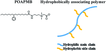
In the present work, we developed an alkali free binary flooding system consisting of the biobased zwitterionic surfactant and hydrophobically associating polymer with ultralow interfacial tension. Zwitterionic surfactants usually have lower critical micelle concentration (CMC),11 better water solubility12 and satisfied interfacial tensions.13 The biobased zwitterionic surfactant (N-phenyloctade-canoicamidopropyl-N,N-dimethyl-carboxylbetaine, POAPMB) synthesized using renewable feedstock in our laboratory demonstrated excellent surface/interfacial activity and environmental biodegradability, and its CMC was 5.58 × 10⁻⁶ mol L−1.14 The hydrophobically associating polymer (AP-P3) was synthesized in the laboratory as described in published literature.5 The structures of POAPMB and hydrophobically associating polymer were illustrated in Fig. 1. The interfacial tension (IFT), viscosity and phase behavior of the biobased zwitterionic surfactant/hydrophobically associating polymer binary system were investigated, which is, to the best of our knowledge, the first report about the SP flooding of alkali free biobased zwitterionic surfactant and hydrophobically associating polymer flooding system.
Unless otherwise specified, the POAPMB/AP-P3 system configured by Daqing simulated formation water (downhole temperature 45 °C) consisted of 0.50 g L−1 POAPMB (∼0.95 mM) and 1.50 g L−1 AP-P3 in the experiment. The interfacial tensions were measured by a spinning drop interfacial tensiometer at 45 °C. The IFT between simulated formation water and Daqing crude oil (the acid value: 0.06 mg KOH per g) was 9.9 mN m−1 at 45 °C. The viscosity of POAPMB/AP-P3 system was measured by a rheometer at 45 °C.
Dynamic interfacial tensions between Daqing crude oil and different concentrations of surfactant solutions alone and in the presence of 1.50 g L−1 AP-P3 were showed in Fig. 2a and b (ESI Fig. 1a and b†). The ultralow IFT could be achieved at a concentration as low as 0.05 g L−1 (Fig. 2a and ESI Fig. 1a†), which is fifty times lower than that of the sugar-based anionic-nonionic surfactant15 (ESI Table 11†). Most of alkylbenzene sulfonates16 and propyl sulfobetaine17 can not achieve ultralow IFT without alkali.
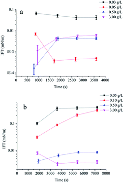 | ||
| Fig. 2 The IFT between crude oil and different concentrations of POAPMB solutions (a) and in the presence of 1.50 g L−1 AP-P3 (b) (n = 3). | ||
For the binary system POAPMB/AP-P3 (1.50 g L−1) solution, the ultralow IFT was reached when the POAPMB concentrations ranged from 0.50 g L−1 to 3.00 g L−1 (Fig. 2b and ESI Fig. 1b†), which implies that the POAPMB/AP-P3 system is promisingly applicable in tertiary oil recovery. The addition of the polymer increased minimum transient IFT (IFTmin), and it is possibly due to the formation of mixed micelle-like associations on the interface led to decline of interfacial free surfactant molecules and the lose adsorption.6,9 In addition, it took more time to achieve the balance of IFT in the presence of the polymer. Compared with nonionic surfactant10 (ESI Table 11†), POAPMB/AP-P3 binary system can effectively reduce interfacial tensions.
In addition to the ultralow IFT, the performances of anti-dilution, stability, adsorption resistance, temperature adaptability, and salt tolerance also play an important role in SP flooding technology. For the anti-dilution, POAPMB/AP-P3 system achieved ultralow IFT when the solution was diluted to one eighth (Table 1). In this case, the viscosity retention rate was 8% (ESI Table 4†). For 3.00 g L−1 POAPMB solution with 1.50 g L−1 AP-P3, ultralow IFT could be achieved even if it was diluted to one fortieth (ESI Table 2†).
| Dilution multiple | 0.5 g L−1 POAPMB + 1.5 g L−1 AP-P3 IFTmin (mN m−1) | 0.5 g L−1 POAPMB + 1.5 g L−1 AP-P3 IFTequ (mN m−1) |
|---|---|---|
| 1 | (4.1 ± 0.3) × 10−3 | (8.7 ± 0.3) × 10−3 |
| 2 | (5.9 ± 0.4) × 10−4 | (1.6 ± 0.1) × 10−3 |
| 3 | (6.4 ± 0.5) × 10−4 | (1.5 ± 0.1) × 10−3 |
| 4 | (1.6 ± 0.3) × 10−4 | (2.6 ± 0.2) × 10−3 |
| 5 | (2.9 ± 0.2) × 10−5 | (4.1 ± 0.3) × 10−3 |
| 6 | (9.7 ± 0.6) × 10−5 | (8.0 ± 0.4) × 10−4 |
| 7 | (1.2 ± 0.2) × 10−4 | (6.7 ± 0.5) × 10−3 |
| 8 | (2.4 ± 0.3) × 10−4 | (2.4 ± 0.3) × 10−4 |
| 9 | (5.1 ± 0.3) × 10−1 | (9.9 ± 0.4) × 10−1 |
Table 2 showed that the IFTmin and equilibrium interfacial tension (IFTequ) of the binary system after aging. It could be seen that the IFTmin was below 0.01 mN m−1 after aging for 100 days. The POAPMB/AP-P3 system stability of ultralow IFTequ can last for 60 days. It was reported Gemini-non-ionic mixed surfactant and polymer stability of ultralow IFT can last for 90 days5 (ESI Table 11†).
| Days | 0.50 g L−1 POAPMB + 1.50 g L−1 AP-P3 IFTmin (mN m−1) | 0.50 g L−1 POAPMB + 1.50 g L−1 AP-P3 IFTequ (mN m−1) |
|---|---|---|
| 0 | (4.1 ± 0.3) × 10−3 | (8.7 ± 0.3) × 10−3 |
| 2 | (3.1 ± 0.2) × 10−3 | (6.6 ± 0.4) × 10−3 |
| 4 | (2.0 ± 0.2) × 10−4 | (3.3 ± 0.3) × 10−3 |
| 7 | (1.5 ± 0.1) × 10−4 | (3.0 ± 0.1) × 10−3 |
| 10 | (2.3 ± 0.3) × 10−4 | (3.7 ± 0.2) × 10−3 |
| 15 | (2.0 ± 0.4) × 10−4 | (3.4 ± 0.3) × 10−3 |
| 30 | (7.2 ± 0.5) × 10−5 | (8.0 ± 0.5) × 10−4 |
| 60 | (3.5 ± 0.3) × 10−3 | (9.2 ± 0.6) × 10−3 |
| 100 | (4.8 ± 0.3) × 10−3 | (3.7 ± 0.3) × 10−2 |
The binary system and Daqing oil sands were mixed at the weight fraction ratio of 9/1. The mixture was shook at 45 °C for 24 h by shaking water bath. The IFT between Daqing crude oil and the supernatants was then measured. If the value of IFT was below 0.01 mN m−1, fresh sands were added to the remaining supernatants at the same weight fraction. Repeat the above operation until the IFT of the solution was above 0.01 mN m−1. The total number of times that an ultralow IFT achieved were taken as the measurement for evaluating the resistance of a surfactant formulation against adsorption by sandstone.2 For the binary system, ultralow IFT was achieved after two cycles (Table 3). At this time, the viscosity retention rate of the binary system was 93% (ESI Table 5†). Ultralow IFT was achieved after three cycles for the solution of 3.00 g L−1 (about 5.71 mM) POAPMB with 1.50 g L−1 AP-P3 (ESI Table 3†). It is recognized that the Daqing oil sands are negatively charged. Due to electrostatic attraction, hydrogen bonding, ion-exchange, chain–chain interaction, covalent bonding, and hydrophobic bonding, as well as solvation of various species,18,19 the saturated adsorption of different types of surfactants followed an order of anionic < nonionic < zwitterionic < cationic surfactants.2,9,10,20 Yan et al.2 reported that a nonionic/zwitterionic formulation with polyacrylamide achieved four times the ultralow IFT (ESI Table 11†).
| Times | 0.5 g L−1 POAPMB + 1.5 g L−1 AP-P3 IFTmin (mN m−1) | 0.5 g L−1 POAPMB + 1.5 g L−1 AP-P3 IFTequ (mN m−1) |
|---|---|---|
| 1 | (4.4 ± 0.4) × 10−4 | (4.4 ± 0.3) × 10−4 |
| 2 | (3.5 ± 0.3) × 10−3 | (3.9 ± 0.2) × 10−3 |
| 3 | (8.8 ± 0.4) × 10−1 | (9.7 ± 0.2) × 10−1 |
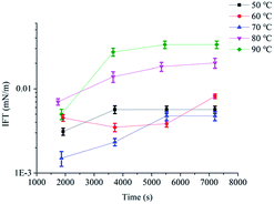
Fig. 3 showed IFTs of POAPMB/AP-P3 system at different temperatures. The IFTmin of POAPMB/AP-P3 system was below 0.01 mN m−1 at 50 °C to 90 °C (Fig. 3 and ESI Fig. 2†). But the IFTequ showed an upward trend and roughly increased for both systems with increasing temperature. The IFTequ at 80 °C and 90 °C were above 0.01 mN m−1 (Fig. 3 and ESI Fig. 2†). Probably because the hydrophobic interactions among surfactant molecules became weaker with the temperature increase,21 making the array of the interfacial surfactant molecule looser.18,22 Moreover, when the temperature of the system increased and the molecular motion speeds up accordingly, the solvent molecules in the interface layer may be increased.21 The viscosity of the binary system was 32.8 mPa s at 70 °C (ESI Table 6†).
The effects of NaCl and Ca2+ concentration (CaCl2 was added in the solution) on IFT were showed in Fig. 4 and 5 (ESI Fig. 3 and 4†). Ultralow IFTequ was achieved when the concentration of NaCl below 15.00 g L−1 and the concentration of Ca2+ below 400 mg L−1. The excessive electrolyte ions destroy the hydration film around the hydrophilic head, promoting the surfactants on the oil/water interface to transfer to the oil phase and the interface tension increases with a reduction of aggregation degree.15,23 The salinities of most oil fields are normally below 16.00 g L−1 and the concentrations of Ca2+ are below 300 mg L−1![[thin space (1/6-em)]](https://www.rsc.org/images/entities/char_2009.gif) 14,24 in Chinese oilfields. The present results suggested that POAPMB/AP-P3 system had strong electrolyte tolerance, and it could remain good interfacial properties in a wide range of salinity. The viscosity retention rates of POAPMB/AP-P3 system were 55% and 77% at the conditions of 12.50 g L−1 NaCl and 200 mg L−1 Ca2+, respectively (ESI Table 7 and 8†), which implied a possibility for its application in most oil fields in China.
14,24 in Chinese oilfields. The present results suggested that POAPMB/AP-P3 system had strong electrolyte tolerance, and it could remain good interfacial properties in a wide range of salinity. The viscosity retention rates of POAPMB/AP-P3 system were 55% and 77% at the conditions of 12.50 g L−1 NaCl and 200 mg L−1 Ca2+, respectively (ESI Table 7 and 8†), which implied a possibility for its application in most oil fields in China.
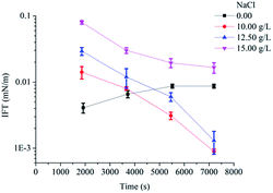 | ||
| Fig. 4 Effects of concentrations of NaCl on the IFTs between crude oil and POAPMB/AP-P3 system (n = 3). | ||
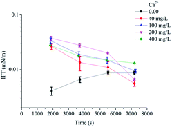 | ||
| Fig. 5 Effects of concentrations of Ca2+ on the IFTs between crude oil and POAPMB/AP-P3 system (n = 3). | ||
Table 4 showed the viscosity of AP-P3 simulated formation water solution and POAPMB/AP-P3 system with aging time. The initial viscosity retention rate of POAPMB/AP-P3 system was 80%. Guo et al.5 reported that the initial viscosity retention rate of fatty acid disulfonate with hydrophobically associating polyacrylamide was 67% (ESI Table 11†). The addition of POAPMB lowered the viscosity of polymer. Biggs et al. found that with the concentration of sodium dodecyl sulfate increased the viscosity of hydrophobically modified polyacrylamide solution rose first and felled later and accordingly proposed a three-stage model.25 The same phenomenon was observed in cation surfactant,26 zwitterionic surfactant27 and nonionic28–30 surfactants and hydrophobically associating polymer systems. The surfactant may incorporate to the polymer molecules in the form of spherical micelles.31 When the concentration of surfactant was high, hydrophobic region of hydrophobically associating polymer became solubilized by a single micelle. As a result, intermolecular association effects weakened and polymer network was destroyed (Region III),25 and the viscosity decreased. The viscosity of both solutions decreased over time. The viscosity retention rate after 30 days was 72% for POAPMB/AP-P3 system, which implied a good viscosity stability.
| Days | 1.5 g L−1 AP-P3 viscosity (mPa s) | 0.5 g L−1 POAPMB + 1.5 g L−1 AP-P3 viscosity (mPa s) |
|---|---|---|
| 0 | 58.4 ± 0.5 | 46.8 ± 0.4 |
| 2 | 51.6 ± 0.4 | 44.9 ± 0.3 |
| 4 | 52.4 ± 0.4 | 40.9 ± 0.3 |
| 7 | 51.6 ± 0.5 | 42.0 ± 0.4 |
| 10 | 50.6 ± 0.4 | 38.2 ± 0.2 |
| 15 | 50.2 ± 0.4 | 37.1 ± 0.3 |
| 30 | 43.0 ± 0.3 | 33.8 ± 0.2 |
| 60 | 35.1 ± 0.3 | 26.2 ± 0.2 |
| 100 | 32.7 ± 0.2 | 22.4 ± 0.1 |
Microemulsions are thermodynamically stable, macroscopically homogeneous mixtures of water, oil and one or more amphiphilic compounds. Microscopically, the surfactant molecules may form a film separating the two incompatible solvents into two domains.32 An O/W middle phase microemulsion can been observed in the tube. “Solubilization ratio for oil (water) is defined as the ratio of the solubilized oil (water) volume to the surfactant volume in the microemulsion phase”.33 Solubilization ratio for oil need to be higher than 10 as an effective surfactant flooding.33 According to observation and calculation, the solubilization ratio for oil was 40 for POAPMB/AP-P3 system (Fig. 6). The particle size measurement (ESI Table 9†) showed that the polymer aggregates were formed in the bottom phase, and the surfactant molecules stayed in the middle phase as reported.33 The zeta potential of middle phase microemulsion was −50.4 mV (ESI Table 10†), which implied the surfactant molecules formed an electrical double layer at the oil-aqueous interface.34 In general, values greater than ±30 mV suggested a good stability of the emulsions.34,35 In addition, emulsification of the crude oil to form the O/W emulsion is beneficial for high recovery.2
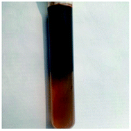 | ||
| Fig. 6 Photograph of crude-oil-in-simulated formation water middle phase microemulsion taken after 3 weeks of settling 45 °C. | ||
Conclusions
The ultralow interfacial tension can be achieved in a low dosage of the biobased zwitterionic surfactant in the binary surfactant–polymer flooding system. The binary system exhibited a good anti-dilution and adsorption resistance, and it can keep ultralow IFTequ after 60 days; meanwhile, it showed an excellent salt resistance and good temperature adaptability. When mixed with crude oil, the O/W middle phase microemulsion was formed and effective solubilization of crude oil was achieved, which implies that the binary flooding system is a kind of novel and cost-effective alkali free surfactant–polymer flooding system and is potential application in EOR.Conflicts of interest
There are no conflicts of interest to declare.Acknowledgements
This research was supported by the National Key Research and Development Program of China (No. 2017YFB0308900), and National Natural Science Foundation of China (No. 51574125).Notes and references
- G. J. Hirasaki, C. A. Miller and M. Puerto, SPE J., 2011, 16, 889–907 CrossRef.
- L. M. Yan, Y. L. Li, Z. G. Cui, B. L. Song, X. M. Pei and J. Z. Jiang, Energy Fuels, 2017, 31, 9319–9327 CrossRef.
- H. Clara, L. J. Chacon, A. Lorenzo, B. Abel, Q. Jie, C. Phillip and M. J. Pitts, SPE Reservoir Eval. Eng., 2003, 6, 147–156 CrossRef.
- K. Zhang and J. S. Qin, Pet. Sci. Technol., 2011, 29, 183–191 CrossRef.
- Y. J. Guo, J. X. Liu, X. M. Zhang, R. S. Feng, H. B. Li, J. Zhang, X. Lv and P. Y. Luo, Energy Fuels, 2012, 26, 2116–2123 CrossRef.
- W. X. Situ, H. M. Lu, C. Y. Ruan, L. Zhang, Y. Zhu and L. Zhang, Colloids Surf., A, 2017, 533, 231–240 CrossRef.
- P. Q. Gao, B. F. Towler, Y. Li and X. F. Zhang, SPE EOR Conference at Oil & Gas West Asia, Muscat, Oman, 2010 Search PubMed.
- Y. Zhu, G. Jian, W. Liu, L. Cheng, Q. Hou and J. Li, SPE Enhanced Oil Recovery Conference, Kuala Lumpur, Malaysia, 2013 Search PubMed.
- Z. G. Cui, D. Qi, B. L. Song, X. M. Pei and X. Hu, Energy Fuels, 2016, 30, 2043–2051 CrossRef.
- L. M. Yan, Z. G. Cui, B. L. Song, X. M. Pei and J. Z. Jiang, Energy Fuels, 2017, 31, 3821–3829 CrossRef.
- A. Bera, S. Kissmathulla, K. Ojha, T. Kumar and A. Mandal, Energy Fuels, 2012, 26, 3634–3643 CrossRef.
- A. Kumar and A. Mandal, Colloids Surf., A, 2018, 549, 1–12 CrossRef.
- N. Li, G. Zhang, J. Ge, J. Luchao, Z. Jianqiang, D. Baodong and H. Pei, Energy Fuels, 2011, 25, 4430–4437 CrossRef.
- Q. Q. Zhang, B. X. Cai, H. Z. Gang, S. Z. Yang and B. Z. Mu, RSC Adv., 2014, 4, 38393–38399 RSC.
- T. H. Zhao, J. Y. Gu, W. F. Pu, Z. M. Dong and R. Liu, RSC Adv., 2016, 6, 70165–70173 RSC.
- C. Zhao, Y. Jiang, M. Li, T. Cheng, W. Yang and G. Zhou, RSC Adv., 2018, 8, 6169–6177 RSC.
- J. Zhao, C. Dai, Q. Ding, M. Du, H. Feng, Z. Wei, A. Chen and M. Zhao, RSC Adv., 2015, 5, 13993–14001 RSC.
- S. Paria and K. C. Khilar, Adv. Colloid Interface Sci., 2004, 110, 75–95 CrossRef PubMed.
- R. Zhang and P. Somasundaran, Adv. Colloid Interface Sci., 2006, 123–126, 213–229 CrossRef PubMed.
- Z. G. Cui, W. Li, J. J. Qi and H. J. Wang, Colloids Surf., A, 2012, 414, 180–189 CrossRef.
- Y. Cao, R. H. Zhao, L. Zhang, Z. C. Xu, Z. Q. Jin, L. Luo, L. Zhang and S. Zhao, Energy Fuels, 2012, 26, 2175–2181 CrossRef.
- H. Zhou, H. Wu, Y. Yang, X. Leng, Y. Liang, P. Lian, Y. Song, Z. Yi, J. Liu and H. Jia, RSC Adv., 2017, 7, 32413–32418 RSC.
- A. Bera, A. Mandal and B. Guha, J. Chem. Eng. Data, 2013, 59, 89–96 CrossRef.
- L. Y. Wang, R. Y. Duan, J. F. Liu, S. Z. Yang, J. D. Gu and B. Z. Mu, Biogeosciences, 2012, 9, 4645–4659 CrossRef.
- S. Biggs, J. Selb and F. Candau, Langmuir, 1992, 8, 838–847 CrossRef.
- R. E. Jimenez, J. Selb and F. Candau, Langmuir, 2000, 16, 8611–8621 CrossRef.
- S. Feng, H. Chen, Z. Hong, L. Xiao and J. Xian, Appl. Chem. Ind., 2015, 44, 87–91 Search PubMed.
- S. Talwar, J. Harding, K. R. Oleson and S. A. Khan, Langmuir, 2009, 25, 794–802 CrossRef PubMed.
- S. Talwar, L. Scanu, S. R. Raghavan and S. A. Khan, Langmuir, 2008, 24, 7797–7802 CrossRef PubMed.
- R. Liu, W. Pu, L. Wang, Q. Chen, Z. Li, Y. Li and B. Li, RSC Adv., 2015, 5, 69980–69989 RSC.
- R. D. W. And, T. Cosgrove and L. Thompson, Langmuir, 2012, 15, 8376–8382 Search PubMed.
- S. Nave, F. Testard, H. Coulombeau, K. Baczko, C. Larpent and T. Zemb, Phys. Chem. Chem. Phys., 2009, 11, 2700–2707 RSC.
- J. J. Sheng, Modern Chemical Enhanced Oil Recovery Theory and Practice, Elsevier, USA, 2011 Search PubMed.
- N. Kumar and A. Mandal, Energy Fuels, 2018 DOI:10.1021/acs.energyfuels.8b00043.
- A. Bera, S. Kumar and A. Mandal, J. Chem. Eng. Data, 2012, 57, 3617–3623 CrossRef.
Footnote |
| † Electronic supplementary information (ESI) available. See DOI: 10.1039/c8ra02901f |
| This journal is © The Royal Society of Chemistry 2018 |

