 Open Access Article
Creative Commons Attribution 3.0 Unported Licence
Construction of g-C3N4 and FeWO4 Z-scheme photocatalyst: effect of contact ways on the photocatalytic performance†
Cong Wang‡
,
Guanlong Wang‡,
Xiufang Zhang *,
Xiaoli Dong,
Chun Ma,
Xinxin Zhang,
Hongchao Ma and
Mang Xue
School of Light Industry and Chemical Engineering, Dalian Polytechnic University, Dalian, China 116034. E-mail: zhangxf010807@163.com; Fax: +86 411 86323736; Tel: +86 411 86323508
First published on 21st May 2018
Abstract
Photocatalysis has been regarded as an attractive strategy for the elimination of contaminants, but its performance is usually limited by the fast recombination of photogenerated electron–holes. A heterojunction photocatalyst could achieve the effective separation of electron–holes. However, the electrons migrate to the less negative band while holes move to the less positive band, leading to a weakened redox ability. Z-scheme photocatalysis is a feasible way to realize the efficient separation of photogenerated electron–holes without sacrificing the reductive ability of electrons and oxidative ability of holes. In this work, a new Z-scheme photocatalyst, composed of g-C3N4 (photocatalyst I), FeWO4 (photocatalyst II) and RGO (electron mediator), was fabricated through a facile hydrothermal and mixing method. The effect of contact ways (the electron mediator firstly combined with photocatalyst I or with photocatalyst II) on the Z-scheme photocatalytic performance was investigated. The photocatalytic removal rate of rhodamine B (RhB) was largely enhanced by the construction of a Z-scheme photocatalyst, compared with the g-C3N4/FeWO4 composite without RGO. The contact ways could affect the photocatalytic ability of a Z-scheme photocatalyst. The enhanced photocatalytic performance was attributed to the Z-scheme induced efficient separation of photogenerated charge carriers. Furthermore, remaining holes (on the VB of FeWO4) or remaining electrons (on the CB of g-C3N4) with powerful oxidation or reduction ability would promote the photocatalytic degradation of RhB.
1. Introduction
Over the past few decades, semiconductor photocatalysis has been widely applied in the destruction of organic pollutants in air or water.1,2 Various semiconductor materials, such as oxides,3 sulfides,4 nitrides,5 or solid solutions,6 have been exploited as single-phase photocatalysts. However, rapid recombination of the photoexcited electron–hole pairs usually occurs in single-phase photocatalysis, which will restrict the photocatalytic activity. To address this issue, composite photocatalysts are commonly used to make efficient charge carrier separation.7–10 Nevertheless, photogenerated electrons in a composite photocatalysts migrate to and accumulate in less negative conduction bands, while holes migrate to and accumulate in less positive valence bands. Thus, from the point of view of thermodynamics, the oxidation performance of holes or the reduction ability of electrons is weakened compared with single-component photocatalysts. The Z-scheme photocatalytic system, which proceeds through a two-step photoexcitation (PS II of a photocatalytic oxidation system and PS I of a photocatalytic reduction system), is deemed to be an ideal approach to overcome this drawback.11–13 The Z-scheme photocatalytic system employs two photocatalysts (photocatalyst I for PS I and photocatalyst II for PS II) and a suitable electron transfer mediator. Photogenerated electrons within PS II combine with holes within PS I via the electron mediator. Thus, electrons with a high reduction ability in PS I and holes with a high oxidation ability in PS II are preserved and participate in the subsequent surface reaction. This unique advantage of powerful redox ability makes the Z-scheme system superior for water splitting and pollutant degradation. However, very limited progress in the construction of a Z-scheme system has been achieved, as it is difficult to control the desirable combination of holes and electrons via an electron mediator. The key point is that intimate interaction between the two photocatalysts must occur to allow the charge transfer. Up to now, some Z-scheme photocatalytic systems have been constructed for water splitting or pollutant decomposition.14–19 However, the effect of contact ways (the electron mediator firstly combined with photocatalyst I or with photocatalyst II) on the Z-scheme photocatalytic performance has not been thoroughly explored.It has been proved that bulk g-C3N4, as a metal-free photocatalyst with a band gap of about 2.8 eV, can eliminate organic pollutants in water and split water under visible light irradiation.20,21 In 2009, Wang et al. first reported the use of g-C3N4 for hydrogen or oxygen production from water splitting under visible light irradiation.22,23 It is usually synthesized via a series of heating treatments from a simple precursor such as low-cost melamine.24 The CB and VB levels of g-C3N4 are −1.4 eV and 1.4 eV vs. NHE, respectively.25 So it is a promising candidate for photocatalyst I due to its relatively negative conduction band level. FeWO4 is also a visible-light-driven photocatalyst, which can decompose some pollutants via photocatalysis. In previous work, Kovacs et al. first prepared FeWO4 through a general hydrothermal method.26 Gao et al. also reported the synthesis of FeWO4 microplates in a general low-temperature hydrothermal route.27 The prepared three-dimensional FeWO4 materials displayed excellent photocatalytic activity. It is chosen as photocatalyst II because of its relatively positive valence band potential (3.2 eV vs. NHE). Furthermore, the band potential matching is another point to be considered for the construction of a Z-scheme photocatalytic system. That is, the conduction band potential of photocatalyst II should be more negative than that of the valence band of photocatalyst I. The conduction band potential of FeWO4 is 0.4 eV vs. NHE, which is more negative than that of the valence band of g-C3N4. RGO, a solid electron transfer medium for a Z-scheme photocatalytic system, is commonly employed for the combination of photogenerated carriers.28 It is known that RGO possesses good electron transfer ability and a large surface area.29,30 RGO could form tight contacts with two semiconductors and form an electron transfer bridge for Z-scheme induced charge recombination.
In this study, a new Z-scheme photocatalyst, with g-C3N4 as photocatalyst I, FeWO4 as photocatalyst II and RGO as electron mediator was fabricated for enhanced photocatalytic ability. RGO/g-C3N4–FeWO4 (RGO firstly combined with g-C3N4) and RGO/FeWO4–g-C3N4 (RGO firstly combined with FeWO4) were prepared to investigate the effect of the contact ways of the two photocatalysts and the electron mediator on the Z-scheme photocatalytic performance. The photocatalytic ability was evaluated by degradation of rhodamine B (RhB) under visible light.
2. Experimental
2.1 Preparation of photocatalysts
GO was synthesized from natural graphite flakes by a modified Hummers' method.31 GO was dispersed in water by ultrasonication and the GO concentration was 2 mg mL−1.The g-C3N4 was synthesized by calcination. A certain amount of melamine was put into an alumina crucible which was first heated at 550 °C for 4 h with a temperature rise rate of 10 °C min−1. To obtain thin g-C3N4, the above powder was further heated at 550 °C for 4 h with a temperature rise rate of 5 °C min−1. The resultant g-C3N4 was collected for further use.
RGO/FeWO4 was synthesized by a hydrothermal method. In the process, 0.811 g of FeCl3·6H2O (3 mmol) and 0.990 g of Na2WO4·2H2O (3 mmol) were dissolved in 36 mL of deionized water. The solution was kept stirring for 2 h. Then, the prepared GO suspension (14 mL) was dropped into the solution, and the mixture was put into an ultrasonic vibration generator for 30 min. The above mixture was then poured into a 50 mL Teflon-sealed autoclave and heated to 180 °C for 8 h. After that, the precipitate was rinsed with distilled water and alcohol and collected by centrifugation. The above precipitate was dried in an oven at 120 °C for 12 h. In addition, RGO or FeWO4 were fabricated by the same method without an Fe or W source or GO to serve as a control.
RGO/g-C3N4 was fabricated by a hydrothermal process. In detail, the ultra-thin g-C3N4 (95 mg) was dispersed in 45 mL of deionized water by ultrasonication, and then a GO suspension (5 mL) was dispersed in the solution. The pH value of the above mixture was adjusted to 3.5. The above mixture was then added into a 50 mL Teflon-sealed autoclave and heated to 180 °C for 8 h. After that, the precipitate was rinsed with distilled water and alcohol and collected by centrifugation. The obtained precipitate was dried in an oven at 80 °C for 12 h.
FeWO4/g-C3N4 was synthesized by a hydrothermal method. In the process, 0.811 g of FeCl3·6H2O (3 mmol) and 0.990 g of Na2WO4·2H2O (3 mmol) were dissolved in 36 mL of deionized water. The solution was kept stirring for 2 h. Then, the prepared g-C3N4 suspension was added into the solution, and the mixture was put into an ultrasonic vibration generator for 30 min. The above mixture was then poured into a 50 mL Teflon-sealed autoclave and heated to 180 °C for 8 h. After that, the precipitate was rinsed with distilled water and alcohol and collected by centrifugation. The above precipitate was dried in an oven at 120 °C for 12 h.
The Z-scheme photocatalyst, RGO/FeWO4–g-C3N4 was prepared by the following process, g-C3N4 (100 mg) and RGO/FeWO4 (100 mg) were suspended in 50 mL of water, and then the mixture was stirred for 2 h. The precipitate was washed and dried for 5 h under the condition of 80 °C. To prepare composites with identical structures (the photocatalyst combined firstly with RGO will perhaps occupy the “surface active sites” of RGO), FeWO4-RGO/g-C3N4 (FeWO4 and RGO/g-C3N4) were prepared by the same process. And also, FeWO4–g-C3N4 and RGO-FeWO4/g-C3N4 (RGO and FeWO4/g-C3N4) were prepared by the same process as a reference.
2.2 Characterization
The crystal type of a sample was investigated by XRD (Rigaku, Japan) with Cu Kα radiation, an accelerating voltage of 40 kV, and current of 30 mA. A DRS spectrum was recorded using a UV-visible diffuse reflector (UV-2450, Shimadzu, Japan), and the wavelength range was from 200 to 800 nm. The specific surface areas (BET) of the powders were analyzed by the nitrogen adsorption–desorption method using a Micromeritics ASAP 2020 nitrogen adsorption apparatus (USA) at 77 K. PL spectra were obtained on a Fluorescence Spectrometer (LS 55, PerkinElmer, America). The morphology of the photocatalysts was observed using an optical microscope (LEICA; DM 2500M). The surface chemical bonds of the photocatalysts were investigated by XPS. The elemental composition of the synthesized materials was examined by Energy Dispersive X-ray Spectroscopy (EDX).2.3 Measurement of the photocatalytic activity
Photocatalytic activity was evaluated by the degradation of RhB under visible light irradiation. A 300 W Xe lamp was employed as the light source, and the light was passed through a glass filter which could shield any light with a wavelength below 400 nm. Experiments were carried out as follows: the photocatalyst (0.08 g) was suspended in RhB solution (5 mg L−1, 80 mL). Before illumination, the suspension was stirred for 40 min in the dark to ensure the establishment of an adsorption–desorption equilibrium. A specified volume of suspension (5 mL) was collected every 20 min, and the photocatalyst was removed by centrifugation (9500 rpm, 10 min). Then, the residual RhB concentration was calculated by the absorbance of the solution at 554 nm, measured by a UV-vis spectrophotometer (Shimadzu, UV-2450). To clarify the possible oxidizing species in the photocatalytic system, EDTA, p-benzoquinone (BQ), and tert-butyl alcohol (t-BuOH) were employed as scavengers for holes, O2˙−, and ·OH, respectively. The concentration of the scavenger was 1 mM.3. Results and discussion
3.1 XRD characterization
To determine the phase structure, XRD patterns were recorded. Fig. 1(a) shows the XRD patterns of GO and RGO, in which a peak was found at 9.9° in the GO pattern, which corresponds to (001) (d = 0.90 nm),32 and no obvious peak was identified in the RGO pattern, indicating that the regular stacking of GO has been destroyed during the hydrothermal process. Fig. 1(b) shows the XRD patterns of g-C3N4, FeWO4, RGO/g-C3N4, RGO/FeWO4, FeWO4–g-C3N4, RGO/FeWO4–g-C3N4 and FeWO4-RGO/g-C3N4. The XRD pattern of g-C3N4 exhibited a weak peak at 13.01° (d = 0.681 nm) and a strong peak at 27.5° (d = 0.326 nm), which can be indexed to the (002) and (100) diffraction planes of the graphite-like carbon nitride. The (002) diffraction and (100) diffraction relate to the characteristic interlayer stacking structure and the interplanar structural packing. The weak (100) diffraction indicated that the obtained g-C3N4 was thin,33 which could be attributed to the repeated exfoliation by calcination. The main reflection peaks in the FeWO4 pattern could be indexed to a monoclinic structure, according to the standard card (JCPDS-PDF, no. 27-0256).34 When compositing RGO, there were no new peaks in the pattern of RGO/g-C3N4 and RGO/FeWO4, indicating that the introduction of RGO could not change the phase structure of g-C3N4 or FeWO4. A similar conclusion could be drawn based on there being no new founding peaks in the patterns of the other three compounds (FeWO4–g-C3N4, FeWO4-RGO/g-C3N4 and RGO/FeWO4-g-C3N4) compared with the original materials (FeWO4 and g-C3N4, FeWO4 and RGO/g-C3N4, RGO/FeWO4 and g-C3N4). According to Scherrer's equation: D = kλ/β![[thin space (1/6-em)]](https://www.rsc.org/images/entities/char_2009.gif) cos
cos![[thin space (1/6-em)]](https://www.rsc.org/images/entities/char_2009.gif) θ, where D is the average crystal diameter, k is a constant of value 0.89, λ is the radiation wavelength of 0.154 nm, β is the full width at half maximum of the diffraction peak, and θ is the Bragg angle, the crystal size of RGO/FeWO4–g-C3N4 was 45.33 nm. Moreover, the main peaks of the original materials were all observed in the patterns of the compounds, showing that Z-scheme photocatalysts had been successfully prepared.
θ, where D is the average crystal diameter, k is a constant of value 0.89, λ is the radiation wavelength of 0.154 nm, β is the full width at half maximum of the diffraction peak, and θ is the Bragg angle, the crystal size of RGO/FeWO4–g-C3N4 was 45.33 nm. Moreover, the main peaks of the original materials were all observed in the patterns of the compounds, showing that Z-scheme photocatalysts had been successfully prepared.
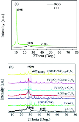 | ||
| Fig. 1 XRD patterns of (a) GO and RGO, and (b) g-C3N4, FeWO4, RGO/FeWO4, RGO/g-C3N4, FeWO4–g-C3N4, FeWO4-RGO/g-C3N4 and RGO/FeWO4–g-C3N4. | ||
3.2 Microscope images
Fig. 2 displays the optical microscope images. In Fig. 2(a), FeWO4 shows a bone-like shape, and its size was 20–30 μm in length and 5 μm in width. In Fig. 2(b), some small black points were found. RGO loading on FeWO4 made the particle image darker. Compared with single FeWO4, the particle size of FeWO4 in RGO/FeWO4 (below 10 μm) was obviously reduced. The exact reason was not clear, but it can be speculated that RGO was a model which restricted the growth of FeWO4 particles. As shown in Fig. 2(c), g-C3N4 was flaky. The image becomes lighter, which could be attributed to good light transmission by thin C3N4. A darker image was found in Fig. 2(d), indicating that RGO and g-C3N4 were successfully hybridized. In Fig. 2(e), it was found that RGO/g-C3N4 was successfully and uniformly loaded onto FeWO4 particles. From Fig. 2(f), g-C3N4 was successfully loaded onto RGO/FeWO4 particles, and maintained a uniformity of distribution, which could promote charge transfer between the materials. The elemental composition of the different synthesized materials was examined by EDX. As shown in Table S1,† RGO/FeWO4–g-C3N4 and FeWO4-RGO/g-C3N4 are composed of C, N, O, Fe and W. Compared with the weight ratio of C/N in g-C3N4 (0.64), the weight ratios of C/N in RGO/FeWO4–g-C3N4 (0.76) and FeWO4-RGO/g-C3N4 (0.81) are higher. This means that RGO has been successfully introduced.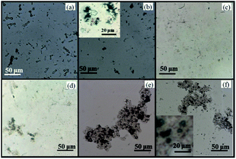 | ||
| Fig. 2 Optical microscope images of FeWO4 (a), RGO/FeWO4 (b), g-C3N4 (c), RGO/g-C3N4 (d), FeWO4-RGO/g-C3N4 (e) and RGO/FeWO4–g-C3N4 (f). | ||
3.3 BET
The specific surface area is an important parameter for photocatalysts, because photocatalysis mainly occurs on and near the surface of photocatalysts. The specific surface area was determined by N2 adsorption/desorption, and the calculated values are displayed in Table 1. It can be seen from Table 1 that the specific surface area of FeWO4 was 24.8 m2 g−1. After coupling with RGO, the BET value of FeWO4/RGO increased (38.4 m2 g−1), which could be ascribed to the large specific surface area of RGO and the deceased particle size of FeWO4. Due to its thin layer structure, g-C3N4 possessed a large surface area (86.7 m2 g−1). Compared with that of g-C3N4, the specific surface area of RGO/g-C3N4 (83.9 m2 g−1) did not obviously change because of the similar specific surface areas of RGO and g-C3N4. Table 1 also shows that RGO/FeWO4–g-C3N4 and FeWO4-RGO/g-C3N4 had similar specific surface areas.| Sample | RGO | FeWO4 | RGO/FeWO4 | g-C3N4 | RGO/g-C3N4 | FeWO4–g-C3N4 | FeWO4-RGO/g-C3N4 | RGO/FeWO4–g-C3N4 |
| BET (m2 g−1) | 178.5 | 24.8 | 38.4 | 86.7 | 83.9 | 75.6 | 75.3 | 75.3 |
3.4 XPS
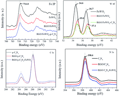
To discover the surface chemical bonds of the photocatalysts, XPS was recorded and the results are shown in Fig. 3. The Fe 2p spectrum of FeWO4 exhibited one peak (710.0 eV), and no obvious shift in peaks was found in the spectra of RGO/FeWO4 or RGO/FeWO4–C3N4. However, in the W 4f spectra, higher binding energies of RGO/FeWO4 and RGO/FeWO4–C3N4 (35.0 eV and 37.1 eV) were determined compared with those of FeWO4 (34.6 and 36.7 eV). The XPS results first revealed that the chemical environment of W was changed after RGO coupling, which could be attributed to the generation of chemical bonds between RGO and FeWO4 during the hydrothermal process. A similar result was also found in other literature.34 Furthermore, no new chemical bonds were generated during C3N4 loading onto RGO/FeWO4 by physical mixing. The peak found in the C 1s spectrum of C3N4 centered at 284.6 eV was attributed to the C–C bond of contaminated carbon. The peak at 288.0 eV corresponds to the tertiary carbon C–N3.35 There was no obvious shift in the peaks of RGO/C3N4 and RGO/C3N4–FeWO4, indicating there was no new generation of chemical bonds between RGO and C3N4 in RGO/C3N4 or RGO/C3N4–FeWO4.3.5 DRS
DRS and band gap calculations are illustrated in Fig. 4. Both samples of g-C3N4 and FeWO4 exhibited significant absorption in the visible light region. The band gaps calculated by the Kubelka–Munk function of g-C3N4 and FeWO4 were 2.85 and 2.81 eV, respectively, which were similar to the reported values.27,29 RGO/FeWO4–g-C3N4 and FeWO4-RGO/g-C3N4 showed enhanced absorption intensity compared with C3N4 and FeWO4, especially in the range of 400-800 nm. It was speculated that the dark color of the powders made them absorb more photons.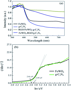 | ||
| Fig. 4 (a) DRS and (b) band gap calculation by the Kubelka–Munk function of FeWO4, g-C3N4, FeWO4-RGO/g-C3N4 and RGO/FeWO4–g-C3N4. | ||
3.6 PL spectra
PL spectra analysis was used to discover the separation efficiency of photogenerated charge carriers in semiconductors. A larger PL intensity means more recombination of photogenerated charge pairs. In the detected PL spectra (Fig. 5), the intensity of RGO/g-C3N4–FeWO4 was lower than that of RGO/g-C3N4, and the intensity of RGO/g-C3N4 was smaller than that of g-C3N4. The result indicated that loading RGO onto g-C3N4 could improve the separation performance of photogenerated charge carriers, caused by the migration of photogenerated electrons from g-C3N4 to RGO. The lowest PL intensity of RGO/g-C3N4–FeWO4 indicated that the separation of photogenerated charge carriers could be improved through the construction of a Z-scheme system. A similar conclusion could be reached by comparing the PL intensity with FeWO4, RGO/FeWO4 and RGO/FeWO4–g-C3N4, which further confirmed the enhanced separation of photogenerated charge carriers in the Z-scheme photocatalyst. With respect to a comparison of RGO/g-C3N4–FeWO4 and RGO/FeWO4–g-C3N4, the PL intensity of RGO/FeWO4–g-C3N4 was slightly lower, indicating that the separation of photogenerated charge carriers on it was more effective. Since less recombination of photogenerated charge carriers leads to better photocatalytic efficiency, it could be expected that the Z-scheme photocatalyst would have high photocatalytic ability, and RGO/FeWO4–g-C3N4 would have the highest photocatalytic performance.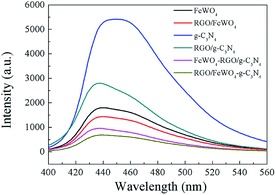 | ||
| Fig. 5 PL spectra of FeWO4, RGO/FeWO4, g-C3N4, RGO/g-C3N4, g-C3N4–FeWO4, FeWO4-RGO/g-C3N4 and RGO/FeWO4–g-C3N4. | ||
3.7 Photocatalytic activity
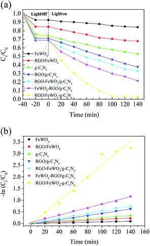
The photocatalytic performances of the photocatalysts were evaluated through RhB degradation under visible light irradiation, and the results are shown in Fig. 6. From Fig. 6(a), before light irradiation, only 7.4% of RhB was removed on FeWO4 after 20 min, meaning that the adsorption of RhB on FeWO4 was poor. After RGO loading, 23.9% of RhB with g-C3N4 was removed, which could be attributed to the large specific surface area of RGO. RhB removal on RGO/g-C3N4 was slightly improved compared with that on g-C3N4, which is possibly attributed to the small difference between the specific surface areas of g-C3N4 and RGO/g-C3N4. The RhB removals on FeWO4–g-C3N4, FeWO4-RGO/g-C3N4 and RGO/FeWO4–g-C3N4 were similar to that of RGO/g-C3N4. After visible light illumination for 120 min, about 15.0% of RhB was removed in the presence of FeWO4, and the removal on g-C3N4 was 31.2%, indicating that FeWO4 and g-C3N4 could be excited by visible light and could degrade RhB in a photocatalytic process. After RGO hybridisation, under the same reaction conditions, the removals of RhB on RGO/FeWO4 and RGO/g-C3N4 were 32.1% and 58.4%, respectively. The enhanced photocatalytic ability could be attributed to the improved separation of photogenerated charge carriers of RGO/FeWO4 and RGO/g-C3N4.RhB removals by FeWO4-RGO/g-C3N4 and RGO/FeWO4–g-C3N4 were 73.5% and 92.3%, respectively, which were higher than those of previously mentioned photocatalysts, certifying that a Z-scheme structure could boost the photocatalytic efficiency. To further confirm the Z-scheme effect, the photocatalytic ability of FeWO4–g-C3N4 and RGO/FeWO4–g-C3N4, which had the same amounts of g-C3N4, FeWO4 and RGO to those of FeWO4-RGO/g-C3N4 and RGO/FeWO4–g-C3N4 was evaluated as a reference. Under the same conditions, the RhB removal rates were significantly lower than those of FeWO4-RGO/g-C3N4 and RGO/FeWO4–g-C3N4, confirming that the enhanced photocatalytic performance of FeWO4-RGO/g-C3N4 and RGO/FeWO4–g-C3N4 was owing to the Z-scheme effect. The photocatalytic ability of RGO/FeWO4–g-C3N4 was higher than that of FeWO4-RGO/g-C3N4, suggesting that the contact ways (the electron mediator firstly combined with photocatalyst I or with photocatalyst II) could affect the Z-scheme photocatalytic performance. The photocatalytic process is fitted well with a pseudo-first-order reaction, and the kinetic curves of RhB degradation are depicted in Fig. 6(b). The kinetic constants of RhB degradation on FeWO4, RGO/FeWO4, g-C3N4, RGO/g-C3N4, RGO-FeWO4/g-C3N4, FeWO4-RGO/g-C3N4 and RGO/FeWO4–g-C3N4 were calculated to be 0.00069, 0.0016, 0.0024, 0.0046, 0.0053, 0.0080 and 0.025 min−1, respectively. To elucidate the influence of RGO on the photocatalytic performance of RGO/FeWO4–g-C3N4, the RGO content in RGO/FeWO4–g-C3N4 was regulated. The results showed that RGO/FeWO4–g-C3N4 with the addition of 14 mg of RGO showed the best performance. The detailed information is displayed in Fig. S1.† The stability of g-C3N4-RGO/FeWO4 for the photocatalytic degradation of RhB was tested, as shown in Fig. 7. The photocatalytic activity of g-C3N4-RGO/FeWO4 shows almost no change after 5 recycling runs, and the RhB removal was maintained at above 90%. This result suggests that g-C3N4-RGO/FeWO4 possesses good stability and recyclability, which are significant for practical applications.
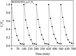 | ||
| Fig. 7 The stability of RGO/FeWO4–g-C3N4 for photocatalytic degradation of RhB under visible light illumination. | ||
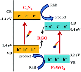
The reason for the improved photocatalytic performance was not exactly clear. It may be caused by the decreased FeWO4 particle size in RGO/FeWO4–g-C3N4, or the force deference of chemical bond (RGO and FeWO4 in RGO/FeWO4–g-C3N4) and physical contact (RGO and g-C3N4 in FeWO4-RGO/g-C3N4). A possible mechanism for RhB degradation with RGO/FeWO4–g-C3N4 as the photocatalyst was proposed and is shown in Scheme 1. When irradiated, the g-C3N4 and FeWO4 particles were excited and generated electrons and holes. Due to the match of the band positions, photogenerated electrons in FeWO4 would combine with holes in g-C3N4 through RGO (the electron mediator). The photogenerated holes in FeWO4 and photogenerated electrons in g-C3N4 were spatially separated. Thus, the separation of photogenerated holes and electrons was enhanced, and more electrons and holes would participate in the oxidation reaction. Meanwhile, remaining holes (on the VB of FeWO4) and electrons (on the CB of the g-C3N4) would promote the photocatalytic degradation of RhB because of its powerful oxidation ability and excellent reduction performance.
To further clarify the possible oxidizing species in the photocatalytic system, a radical quenching experiment was performed. In this experiment, EDTA, p-benzoquinone (BQ), and tert-butyl alcohol (t-BuOH) were employed as scavengers for holes, O2˙−, and ·OH, respectively. Fig. S2a† shows that the photocatalytic efficiency decreased after introducing EDTA and BQ, with the kinetic constant of RhB degradation decreasing from 0.025 min−1 to 0.020 min−1 and 0.017 min−1, respectively (Fig. S2b†), meaning the holes and O2˙− participated in the RhB oxidation. When t-BuOH was added, the decrease in performance was more significant. The kinetic constant of RhB degradation decreased to 0.0084 min−1, suggesting that ·OH was the major oxidant in the photocatalytic system.
4. Conclusions
Z-scheme photocatalysts, in which g-C3N4, FeWO4 and RGO served as photocatalyst I, photocatalyst II and electron mediator, respectively, were successfully fabricated. The photocatalytic degradation rate of RhB was largely enhanced by the construction of a Z-scheme photocatalyst. The contact ways (the electron mediator firstly combined with photocatalyst I or with photocatalyst II) could influence the photocatalytic ability of the Z-scheme photocatalyst. The enhanced photocatalytic performance was attributed to the Z-scheme effect induced efficient separation of photogenerated electrons and holes. Furthermore, accumulated holes (on the VB of FeWO4) with powerful oxidation ability and remaining electrons (on the CB of the g-C3N4) with excellent reduction ability would promote the photocatalytic degradation of RhB. It was rationally confirmed that constructing a Z-scheme photocatalyst was a versatile method to explore a high performance photocatalyst, and the Z-scheme photocatalytic performance could be controlled by the contact ways.Conflicts of interest
There are no conflicts to declare.Acknowledgements
This work was supported by the National Science Fund of China (Project No. 21577008) and Fundamental Research Funds for Central Universities (Project No. 2016J004).References
- M. Li, C. Feng, W. Hu, Z. Zhang and N. Sugiur, Electrochemical degradation of phenol using electrodes of Ti/RuO2-Pt and Ti/IrO2-Pt, J. Hazard. Mater., 2009, 162, 455–462 CrossRef PubMed.
- S. Girish Kumar and K. S. R. Koteswara Rao, Tungsten-based nanomaterials (WO3 & Bi2WO6): modifications related to charge carrier transfer mechanisms and photocatalytic applications, Appl. Surf. Sci., 2015, 355, 939–958 CrossRef.
- X. Quan, S. Yang, X. Ruan and H. Zhao, Preparation of titania nanotubes and their environmental applications as electrode, Environ. Sci. Technol., 2005, 39, 3770–3775 CrossRef PubMed.
- J. Hu, L. Ren, Y. Guo, H. Liang, A. Cao, L. Wan and C. Bai, Mass production and high photocatalytic activity of ZnS nanoporous nanoparticles, Angew. Chem., Int. Ed., 2005, 44, 1269–1273 CrossRef PubMed.
- M. Tabata, K. Maeda, M. Higashi, D. Lu, T. Takata, R. Abe and K. Domen, Modified Ta3N5 powder as a photocatalyst for O2 evolution in a two-Step water splitting system with an iodate/iodide shuttle redox mediator under visible light, Langmuir, 2010, 26, 9161–9165 CrossRef PubMed.
- D. Wang, T. Kako and J. Ye, Efficient photocatalytic decomposition of acetaldehyde over a solid-solution perovskite (Ag0.75Sr0.25)(Nb0.75Ti0.25)O3 under visible-light irradiation, J. Am. Chem. Soc., 2008, 130, 2724–2725 CrossRef PubMed.
- P. Madhusudan, J. Ran, J. Zhang, J. Yu and G. Liu, Novel urea assisted hydrothermal synthesis of hierarchical BiVO4/Bi2O2CO3 nanocomposites with enhanced visible-light photocatalytic activity, Appl. Catal., B, 2011, 110, 286–295 CrossRef.
- L. Konga, Z. Jiang, H. H. Lai, R. J. Nicholls, T. Xiao, M. O. Jones and P. P. Edwards, Unusual reactivity of visible-light-responsive AgBr–BiOBr heterojunction photocatalysts, J. Catal., 2012, 293, 116–125 CrossRef.
- W. Zhang, Y. Li, C. Wang and P. Wang, Kinetics of heterogeneous photocatalytic degradation of rhodamine B by TiO2-coated activated carbon: Roles of TiO2 content and light intensity, Desalination, 2011, 266, 40–45 CrossRef.
- J. Luo, Y. Wang, D. Cao, K. Xiao, T. Guo and X. Zhao, Enhanced photoelectrocatalytic degradation of 2, 4-dichlorophenol by TiO2/Ru-IrO2 bifacial electrode, Chem. Eng. J., 2018, 343, 69–77 CrossRef.
- K. Iwashina, A. Iwase, Y. H. Ng, R. Amal and A. Kudo, Z-Schematic water splitting into H2 and O2 using metal sulfide as a hydrogen-evolving photocatalyst and reduced graphene oxide as a solid-state electron mediator, J. Am. Chem. Soc., 2015, 137, 604–607 CrossRef PubMed.
- Q. Jia, A. Iwase and A. Kudo, BiVO4-Ru/SrTiO3: Rh composite Z-scheme photocatalyst for solar water splitting, Chem. Sci., 2014, 5, 1513 RSC.
- H. Katsumata, Y. Tachi, T. Suzuki and S. Kaneco, Z-scheme photocatalytic hydrogen production over WO3/g-C3N4 composite photocatalysts, RSC Adv., 2014, 4, 21405 RSC.
- H. Li, X. Quan, S. Chen and H. Yu, Ferroelectric-enhanced Z-schematic electron transfer in BiVO4-BiFeO3-CuInS2 for efficient photocatalytic pollutant degradation, Appl. Catal., B, 2017, 209, 591–599 CrossRef.
- Y. Gong, X. Quan, H. Yu and S. Chen, Synthesis of Z-scheme Ag2CrO4/Ag/g-C3N4 composite with enhanced visible-light photocatalytic activity for 2,4-dichlorophenol, Appl. Catal., B, 2017, 219, 439–449 CrossRef.
- H. Tada, T. Mitsui, T. Kiyonaga, T. Akita and K. Tanaka, All-solid-state Z-scheme is CdS-Au-TiO2 three-component nanojunction system, Nat. Mater., 2006, 5, 782–786 CrossRef PubMed.
- W. K. Jo, T. Adinaveen, J. J. Vijaya and N. C. S. Selvam, Synthesis of MoS2 nanosheet supported Z-scheme TiO2/g-C3N4 photocatalysts for the enhanced photocatalytic degradation of organic water pollutants, RSC Adv., 2016, 6, 10487–10497 RSC.
- F. Wu, X. Li, W. Liu and S. Zhang, Highly enhanced photocatalytic degradation of methylene blue over the indirect all-solid-state Z-scheme g-C3N4-RGO-TiO2 nanoheterojunctions, Appl. Surf. Sci., 2017, 405, 60–70 CrossRef.
- W. Jo and N. C. S. Selvam, Z-scheme CdS/g-C3N4 composites with RGO as an electron mediator for efficient photocatalytic H2 production and pollutant degradation, Chem. Eng. J., 2017, 317, 913–924 CrossRef.
- M. Ye, Z. Zhao, Z. Hu, L. Liu, H. Ji, Z. Shen and T. Ma, 0D/2D Heterojunctions of vanadate quantum dots/graphitic carbon nitride nanosheets for enhanced visible-light-driven photocatalysis, Angew. Chem., 2017, 56, 8407–8411 CrossRef PubMed.
- H. Li, Y. Sun, Z. Y. Yuan, Y. Zhu and T. Ma, Titanium Phosphonate Based Metal-Organic Frameworks with Hierarchical Porosity for Enhanced Photocatalytic Hydrogen Evolution, Angew. Chem., 2018, 57, 3222–3227 CrossRef PubMed.
- X. Wang, K. Maeda, A. Thomas, K. Takanabe, G. Xin, J. M. Carlsson, K. Domen and M. Antonietti, A metal-free polymeric photocatalyst for hydrogen production from water under visible light, Nat. Mater., 2009, 8, 76–80 CrossRef PubMed.
- K. Maeda, X. Wang, Y. Nishihara, D. Lu, M. Antonietti and K. Domen, Photocatalytic activities of graphitic carbon nitride powder for water reduction and oxidation under visible light, J. Phys. Chem. C, 2009, 113, 4940–4947 Search PubMed.
- S. C. Yan, Z. S. Li and Z. G. Zou, Photodegradation performance of g-C3N4 fabricated by directly heating melamine, Langmuir, 2009, 25, 10397–10401 CrossRef PubMed.
- S. Chu, Y. Wang, Y. Guo, J. Feng, C. Wang, W. Luo, X. Fan and Z. Zou, Band structure engineering of carbon nitride: In search of a polymer photocatalyst with high photooxidation property, ACS Catal., 2013, 3, 912–919 CrossRef.
- T. N. Kovacs, G. Pokol, F. Gaber, D. Nagy, T. Igricz, I. E. Lukacs, Z. Fogarassy, K. Balazsi and I. M. Szilagyi, Preparation of iron tungstate (FeWO4) nanosheets by hydrothermal method, Mater. Res. Bull., 2017, 95, 563–569 CrossRef.
- Q. Gao and Z. Liu, FeWO4 nanorods with excellent UV-visible light photocatalysis, Prog. Nat. Sci.: Mater. Int., 2017, 27, 556–560 CrossRef.
- A. Iwase, Y. H. Ng, Y. Ishiguro, A. Kudo and R. Amal, Reduced graphene oxide as a solid-state electron mediator in Z-scheme photocatalytic water splitting under visible light, J. Am. Chem. Soc., 2011, 133, 11054–11057 CrossRef PubMed.
- A. Iwase, Y. H. Ng, Y. Ishiguro, A. Kudo and R. Amal, Reduced graphene oxide as a solid-state electron mediator in Z-scheme photocatalytic water splitting under visible light, J. Am. Chem. Soc., 2011, 133, 11054–11057 CrossRef PubMed.
- F. Wu, X. Li, W. Liu and S. Zhang, Highly enhanced photocatalytic degradation of methylene blue over the indirect all-solid-state Z-scheme g-C3N4-RGO-TiO2 nanoheterojunctions, Appl. Surf. Sci., 2017, 405, 60–70 CrossRef.
- W. S. Hummels Jr and R. E. Offeman, Preparation of Graphitic oxide, J. Am. Chem. Soc., 1958, 80, 1339 CrossRef.
- Q. Xiang, J. Yu and M. Jaroniec, Preparation and enhanced visible-light photocatalytic H2-production activity of graphene/C3N4 composites, J. Phys. Chem. C, 2011, 115, 7355–7363 Search PubMed.
- J. Xu, L. W. Zhang, R. Shi and Y. F. Zhu, Chemical exfoliation of graphitic carbon nitride for efficient heterogeneous photocatalysis, J. Mater. Chem. A, 2013, 1, 14766–14772 Search PubMed.
- S. Li, G. Dong, R. Hailili, L. Yang, Y. Li, F. Wang, Y. Zeng and C. Wang, Effective photocatalytic H2O2 production under visible light irradiation at g-C3N4 modulated by carbon vacancies, Appl. Catal., B, 2016, 190, 26–35 CrossRef.
- G. He, M. Chen, Y. Liu, X. Li and Y. Ju, Hydrothermal synthesis of FeWO4-graphene composites and their photocatalytic activities under visible light, Appl. Surf. Sci., 2015, 351, 474–479 CrossRef.
Footnotes |
| † Electronic supplementary information (ESI) available. See DOI: 10.1039/c8ra02882f |
| ‡ These two authors contributed equally to this work. |
| This journal is © The Royal Society of Chemistry 2018 |

