
 Open Access Article
 This Open Access Article is licensed under a Creative Commons Attribution-Non Commercial 3.0 Unported Licence
Entry and passage behavior of biological cells in a constricted compliant microchannel†
A. Raj and
A. K. Sen *
*
Department of Mechanical Engineering, Indian Institute of Technology Madras, Chennai-600036, India. E-mail: ashis@iitm.ac.in
First published on 7th June 2018
Abstract
We report an experimental and theoretical investigation of the entry and passage behaviour of biological cells (HeLa and MDA-MB-231) in a constricted compliant microchannel. Entry of a cell into a micro-constriction takes place in three successive regimes: protrusion and contact (cell protrudes its leading edge and makes a contact with the channel wall), squeeze (cell deforms to enter into the constriction) and release (cell starts moving forward). While the protrusion and contact regime is insensitive to the flexibility of the channel, the squeeze zone is significantly smaller in the case of a more compliant channel. Similarly, in the release zone, the acceleration of the cells into the microconstriction is higher in the case of a more compliant channel. The results showed that for a fixed size ratio ρ and Ec, the extension ratio λ decreases and transit velocity Uc increases with increase in the compliance parameter fp. The variation in the cell velocity is governed by force due to the cell stiffness Fs as well as that due to the viscous dampening Fd, explained using the Kelvin–Voigt viscoelastic model. The entry time te = m(ρ)k1(1 + fp)k2(Ec)k3 and induced hydrodynamic resistance of a cell ΔRc/R = k(ρ)a(1 + kffp)b(kEEc)c were correlated with cell size ratio ρ, Young's modulus Ec and compliance parameter fp, which showed that both entry time te and the induced hydrodynamic resistance ΔRc are most sensitive to the change in the compliance parameter fp. This study provides understanding of the passage of cells in compliant micro-confinements that can have significant impact on mechanophenotyping of single cells.
1. Introduction
Cell migration plays an important role in various biological processes such as early embryo development, angiogenesis, immune response and cancer metastasis.1 Migration of monocytes and smooth muscle cells to the intimal spaces in the blood vessels results in the development of atherosclerotic and restenosis lesions.2 In vitro investigation and therapy development for diseases related to cell migration requires a thorough understanding of the mechanism of cell migration.3 Further, mimicking of the native environment and modelling of the cell migration are also necessary for such in vitro investigations.Poly(dimethylsiloxane) (PDMS) is proven to be a suitable material for engineering compliant microchannel environments to mimic blood vessels and other organs due to its low cost, transparency, durability, biocompatibility, compliance and ease of fabrication.4–6 Also, the literature reports that by varying the curing agent to elastomer ratio, the flexibility of the PDMS material can be controlled according to the requirements.7 Further, PDMS has been used extensively for the microfabrication of organ on chip devices.4,8–15 Huh et al. (2010) developed a multifunctional microdevice which can mimic the key-structural, functional and mechanical properties of the alveolar–capillary interface of the human lung by utilizing thin (10 μm), porous, compliant PDMS membranes.4 Also, in several other studies, researchers have used PDMS based microchannels to create artificial vasculature networks.8,15 Further, utility of artificially created micropores and micro-capillaries as micro-constrictions using PDMS materials is well proven in studies involving cell mechanophenotyping.16–18
Passage of cells through rigid constricted microchannels have been widely investigated in the literature.16,17,19–21 Shelby et al. (2003) investigated the passage of healthy and malaria infected red blood cells (RBCs) through micro-constriction channels which showed a clear contrast.16 Hou et al. (2009) have shown the differences in the passage behavior of cancerous and healthy breast cell lines MCF-7 and MCF-10A respectively as an indirect measure of the state of the disease.17 In our previous work Raj et al. (2017) we have demonstrated the utility of spherical cell passage through the rigid micro-constrictions towards cell mechanophenotyping.21 Although the microchannels utilized in the above studies mimic the native micropores and micro-capillaries in terms of size, there is significant difference in terms of the flexibility (since the channels were rigid), which is addressed in the present work. Towards this, we reported a compliant microchannel infrastructure whose deformability can be engineered.22
The mechanical property of cells and the capillary walls and their mutual interactions are crucial for healthy functioning of our body. The mechanical property of the capillary walls gets altered in case of diseases such as atherosclerosis results in the stiffening of the arterial walls.23,24 Also, the abnormal narrowing of the arteries in stenosis changes the hydrodynamic resistance encountered by the cells while migrating through the affected areas of the canal. Similarly, in case of cancer, the higher deformability of cells enables them to squeeze through the available pores in the vessel wall to enter into the blood stream and migrate to different locations.25 Understanding of the interaction between deformable objects such as cells with deformable boundaries such as capillary wall or tissue could provide valuable insights to such diseases.
Walter et al. (2011) have studied the interaction of a single-cell with a thin PDMS cantilever, while flowing through a confined microchannel and have characterized the deformation of the cantilever induced by the cell.26 Zheng et al. (2009) have utilized a compliant microchannel as an airway model and investigated the deformation profile of the compliant wall with the progression of a liquid plug inside the channel.27 Lighthill et al. (1968) have analytically investigated the motion of tightly fitted pellets through fluid-filled elastic tubes by incorporating the lubrication film theory.28 Later, Fitz-gerald et al. (1969) demonstrated the relevance of the analytical model developed by Lighthill et al. (1968) towards passage of red blood cells through capillaries.29 In spite of the above developments, the passage of cells inside compliant microchannels has not been studied, which is the focus of the present work.
Previously, we reported generation of microdroplets in a compliant microchannel.30 Here, we report experimental and theoretical studies of the passage behavior of cells in compliant micro-constrictions. The entry and transit behavior of different cell lines in compliant microchannels of different values of flexibility parameter are studied. A theoretical model is developed to predict the hydrodynamic resistance21,31–33 of individual cells of different size and stiffness in compliant channels. First, we provide a brief description of the device used in the experimental and theoretical analysis. Then, we present a theoretical model to predict induced hydrodynamic resistance of a cell migrating through a compliant micro-constriction. Further, materials and methods are enumerated. Finally, results of the experiments and theoretical predictions are presented and discussed.
2. Device description
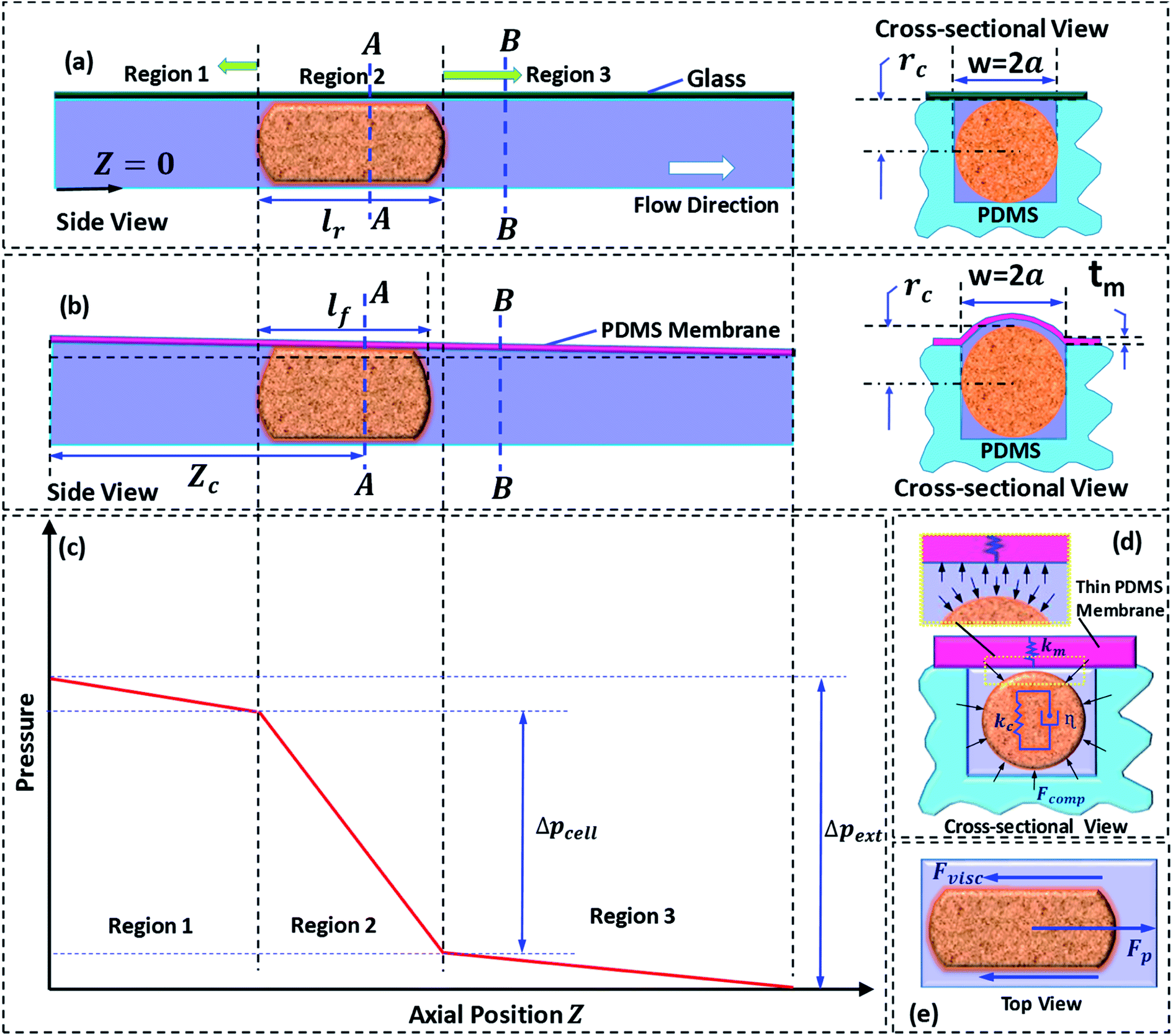
A detailed schematic of the micro-constriction device used in the present study is depicted in Fig. 1. The device has three different zones (Fig. 1a): zone I is the entry zone where the cells enter into the constricted channel, zone II is the constricted channel whose cross-sectional size is smaller than the nominal cell size, zone III is the exit zone in which the cells exit the constricted channel. In this work, we study the behavior of cells during entry into the constricted channel and passage inside the constricted channel. We have utilized two types of micro-constriction devices in our studies. The first device is a rigid micro-constriction (with four rigid walls) which is obtained by bonding a thick PDMS channel layer with a planar glass slide (Fig. 1b). The second device is a compliant micro-constriction prepared by bonding a thick PDMS channel layer with a thin PDMS membrane (of thickness ∼20 μm) (Fig. 1c). The flexibility of the micro-constriction is characterized in terms of compliance parameter fp, which is explained in the Theoretical section (Section 3). | ||
| Fig. 1 Schematic of the micro-constriction device (a) different zones in the micro-constriction device (b) rigid micro-constriction device (c) compliant micro-constriction device (d) entry time te of a cell (e) top-view of a deformed cell. | ||
The entry and transit behavior of cells in the rigid and compliant micro-constrictions are studied under pressure driven condition. The entry behavior is characterized in terms of entry time te and the transit behavior is characterized by the transit velocity Uc. Entry time te of a cell (Fig. 1d) is defined as the time duration from the time instant the leading edge of a cell starts entering the micro-constriction (i.e. Lp = 0) till the time instant the rear end of the cell completely enters into the constriction (i.e. Lp = l), where l is the length of the deformed cell inside the micro-constriction. Similarly, passage time tp of a cell is defined as the time taken by the cell to migrate from Z = 0 to z = Lc. So the average transit velocity Uc is calculated as the ratio of the micro-constriction length Lc and the passage time tp. Fig. 1e shows a zoomed top-view of a deformed cell migrating through the micro-constriction, rc is the radius of the deformed cell, w and ho are the width and the nominal height of the micro-constriction and 2a is the effective hydraulic diameter of the micro-constriction. The induced hydrodynamic resistance31–33 of a cell ΔRc flowing through a constricted microchannel is defined as ΔRc = (ΔRwc − ΔRwoc), where ΔRwc and ΔRwoc are respectively the hydrodynamic resistance of the micro-constriction with and without presence of the cell.
The induced hydrodynamic resistance offered by cells in a microchannel can be used as a parameter to characterize cells on the basis of their size and deformability.34,35 In our previous works,31,32 we have demonstrated sorting of cells of two distinct sizes and deformability by utilizing the differences in the induced hydrodynamic resistances offered. In another work, we have demonstrated the utility of induced hydrodynamic resistance offered by cells in mechanical property characterization of cells.21 Thus, induced hydrodynamic resistance can play an important role in various applications in cell biology.
3. Theoretical model
3.1 Induced hydrodynamic resistance of a cell
We present a theoretical model to predict induced hydrodynamic resistance of a cell flowing through a constricted microchannel (of size smaller than the nominal cell size). Once a cell completely enters into a micro-constriction by adjusting its cytoskeletal structure, there is insignificant change in the deformation of the cell during further passage.36 The state of the cell can be approximated as a cylindrical pellet moving through a micro-constriction (which is confirmed using microscopic images from our experiments). So, we proceed with the theoretical modeling by considering a physical domain in which a cylindrical pellet is moving through a microchannel of hydraulic diameter 2a. The hydraulic diameter 2a is different for the rigid and compliant micro-constrictions. In case of a compliant micro-constriction, 2a is found out by considering the deformed shape of the micro-constriction, which is illustrated later in the section. Previously,22 we had studied pressure-flow characteristics of a compliant microchannel in which the channel flexibility was characterized in terms of compliance parameter fp = (1/72)(w4(1 − νm)/h30tmEm), which is a function of undeformed channel width w and height h0, membrane thickness tm, Young's modulus Em and Poisson's ratio νm. Here, fp = 0 corresponds to a rigid micro-constriction and the value of fp is higher in case of a more compliant channel. This is explained in more details below.In case of one glass and three PDMS walls, thickness of PDMS wall was taken to be ≥6 mm, which does not deform in the range of pressure applied (as shown in our previous work,30 Raj et al. 2016). Moreover, Young's modulus of glass, Em ∼ 100 GPa, is approximately 105-times higher than the Young's modulus of PDMS, Em ∼ 1 MPa, which gives rise to (fp)rigid ∼ 10−5(fp)flexible. Since (fp)rigid is negligible compared to (fp)flexible it is valid to consider (fp)rigid = 0.
Next, we discuss the approach taken for the theoretical modelling. Fig. 2a and b show the side and cross-sectional views of the rigid and compliant micro-constriction respectively for a given flow rate. In case of the rigid micro-constriction, the cross-sectional area of the micro-constriction remains unchanged whereas in case of the compliant micro-constriction, the cross-sectional area is maximum at z = 0 and minimum (undeformed) at z = Lc (as shown in our previous work22). If we divide the micro-constriction containing a cell into three regions (as shown in Fig. 2c), the region II containing the cell will have maximum hydrodynamic resistance. In the present study, the cells are infused into the device under a constant inlet pressure. The applied pressure is distributed across the three regions and the pressure gradient is maximum across the region II as illustrated in Fig. 2c. Although the pressure gradient is maximum across the cell, deflection of the thin membrane in region II will not be more than that in the region I since the pressure in the region II will always be lesser than that in the region I. The pressure distribution along the channel may evolve dynamically as the cell migrates through the channel. We estimated that the maximum deflection of the membrane wall is ∼0.5 μm, which is quite small compared to the nominal channel height 10 μm. Hence, for the theoretical modelling, a steady tapered microchannel of maximum height at z = 0 and minimum (undeformed) height at z = Lc is considered and any dynamic change in the deflection profile is neglected.
 | ||
| Fig. 2 (a) Side view (left) and cross-sectional view (right) of cell passage through a rigid micro-constriction (b) side view (left) and cross-sectional view (right) of cell passage through compliant micro-constriction (c) schematic of pressure variation along the micro-constriction length (d) cross-sectional view of the cell and representation of Kelvin–Voigt viscoelastic model (e) forces acting on the cell during its passage through the micro-constriction. | ||
In case of the rigid micro-constriction, the hydraulic diameter at section A-A (Fig. 2a) can be easily calculated. However, in case of the compliant micro-constriction (Fig. 2b), the hydraulic diameter can be calculated by considering the effective height h of the deformed channel as follows,22
 | (1) |
A detailed derivation of eqn (1) can be found in our previous work.22 The above equation relates the effective height h of the deformed micro-constriction at section A-A with compliance parameter fp and total flow rate Qt, which is currently unknown (since we use constant pressure condition at the device inlet). The hydraulic diameter 2a of the compliant micro-constriction at section A-A (Fig. 2b) can be obtained by utilizing the effective channel height h(z = Zc) as follows,
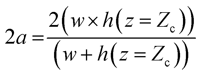 | (2) |
The total flow rate Qt in the micro-constriction (with a cell migrating through micro-constriction), is obtained from first principle by considering the transport of the cell and the leak flow in the annular region around the cell and as follows,
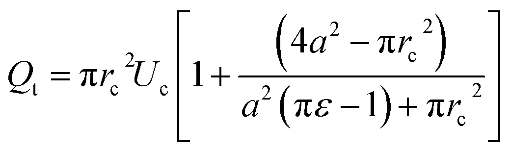 | (3) |
A detailed derivation of the above equation is provided in the ESI Section S.1†. Here, rc is the radius of the deformed cell while migrating through the constriction channel (see Fig. 1e), Uc is the average cell velocity in the micro-constriction, ε is the void fraction which is defined as ε = (Vr − Vc)/Vr, where Vr is the volume of the region II of the micro-constriction and Vc is the volume of the cell.
Applying volume conservation between sections A-A and B-B, we can relate radius of the deformed cell rc with cell velocity Uc and void fraction ε as follows,
 | (4) |
A detailed derivation of the above equation can be found in the ESI Section S.1†. Here, cell velocity Uc and void fraction ε are obtained from experiments using high-resolution and high-speed imaging (see ESI Section S.5†) as a cell migrates through the micro-constriction. Now, we have four equations (i.e. eqn (1)–(4)) which are simultaneously solved using MATLAB to determine the four unknowns (i.e. rc, a, h and Qt).
The pressure drop Δpcell across the region II (in which a cell is present) can be determined as Δpcell = kl, where k is pressure gradient in region II and l is the deformed length of the cell. The pressure drop Δpwc across the region II without presence of a cell can be found out using Hagen–Poiseuille law. Thus, excess pressure drop due to the presence of cell (Δpcell − Δpwc) can yield the induced hydrodynamic resistance offered by a cell as follows, ΔRc = (Δpcell − Δpwc)/Qt. By incorporating the expressions for Δpc, Δpwc, and Qt, the ratio of induced hydrodynamics resistance ΔRc to the nominal resistance of the flow without cell R is given as follows,
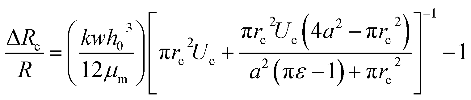 | (5) |
In the above equation, the induced hydrodynamic resistance ΔRc of a cell depends on the effective hydraulic diameter of the micro-constriction 2a which in turn depends on the channel height h(z = Zc). Further, the effective channel height h(z = Zc) depends on the compliance parameter fp (eqn. (1)). Thus, the above equation can be used for predicting hydrodynamic resistance of a cell migrating through compliant (fp ≠ 0) as well as rigid (fp = 0) micro-constriction.
Also, pressure gradient across the cell k can be represented in terms of extension ratio (λ = l/Dcell) as =Δpcell/(Dcell)l; where Dcell is undeformed diameter of the cell. Thus, from eqn (4), it is clear that rc is a function of transit velocity Uc and the extension ratio λ. Hence, eqn (5) relates the induced hydrodynamic resistance offered by the cell (while flowing though the micro-constrictions) with the experimental parameters such as undeformed cell diameter Dcell, transit velocity Uc, hydraulic diameter of the micro-constriction 2a, extension ratio λ and the compliance parameter fp of the channel. We have used eqn (5) to predict the induced hydrodynamic resistance offered by the cell by utilizing the data from experiments for Dcell, Uc, λ, a and fp as will be discussed in Section 5.3.
3.2 Cell deformation and forces acting on a cell
In order to explain the experimental results, we utilize the Kelvin–Voigt viscoelastic solid model.37,38 It is known that most biological cells behave as viscoelastic material. The Kelvin–Voigt viscoelastic model considers a cell to be a combination of mechanical spring with stiffness Kc and damper element with dampening coefficient η connected in parallel, as shown in Fig. 2d. When an external force is applied, the total force response of a cell is the summation of the force responses due to the spring element Fs and the damper element Fd. While migrating through the micro-constriction, a cell must deform to give rise to a change in its diameter as δ = D − 2rc, where D is the undeformed diameter of the cell and rc is the deformed radius of the cell. The force response due to spring element is given by Fs = kcδ and the force response due to the damper element is given by Fd = ηdδ/dt. Thus, it is evident that Fs and Fd have their origin in the deformation δ and the rate of change of deformation respectively. This indicates that if δ ≠ 0, the force response due to stiffness plays a role in the motion of a cell. However, Fd can affect the passage behavior of the cell only if the rate of change of deformation![[small delta, Greek, dot above]](https://www.rsc.org/images/entities/i_char_e14e.gif) exists, which is the case during the entry of a cell into the micro-constriction. Fig. 2e shows the various forces acting on a cell during its passage through the micro-constriction: compressive force due to the pressure in the lubrication layer between the cell and channel wall, viscous drag force and the force due to the pressure gradient driving the flow. In contrast to the rigid channel, in the compliant channel, the wall flexibility dampens the force response of the cell thus can reduce the viscous drag force acting on the cell surface.
exists, which is the case during the entry of a cell into the micro-constriction. Fig. 2e shows the various forces acting on a cell during its passage through the micro-constriction: compressive force due to the pressure in the lubrication layer between the cell and channel wall, viscous drag force and the force due to the pressure gradient driving the flow. In contrast to the rigid channel, in the compliant channel, the wall flexibility dampens the force response of the cell thus can reduce the viscous drag force acting on the cell surface.
4. Materials and methods
We followed photolithography and soft lithography techniques to fabricate the polydimethyl siloxane (PDMS) based micro-constriction device. First, a silicon (Si) master was fabricated using standard lithography process. Further, PDMS containing 10![[thin space (1/6-em)]](https://www.rsc.org/images/entities/char_2009.gif) :1 mixture of elastomer and curing agent was molded using the Si-master to obtain the microchannel layer. The resulting PDMS layer was bonded either to glass or with thin PDMS membrane by using oxygen plasma bonding (Harrick Plasma, Brindley St., USA) to fabricate rigid and flexible micro-constriction devices respectively. A detailed description of the device fabrication procedure is provided in the ESI Section S.2†. Two different kinds of cell lines, human breast cancer cell line MDA-MB-231 and cervical cancer cell line HeLa, that have different stiffness values21,32 were used in our experiments. The MFCS-EZ pressure based flow-controller system along with MAESFLO software (Fluigent, Paris, France) was used to infuse the cell sample (2 × 10⁵ cells per mL of media with 1% pluronic, BASF) into the device. In order to capture the cell passage videos and images in the experiments, we have used Inverted microscope (Carl Zeiss Axiovert A1) coupled with a high-speed camera (FASTCAM SA3 model, Photron USA, Inc.) interfaced with PC via Photron Fastcam Viewer 3 software. For image analysis, Photon FASTCAM Analysis (PFA) software (Motion Analysis Software Version 1.3.2.0, Photron USA Inc.) was used. A detailed description of the cell culture protocol, experimental setup and procedure, and image analysis for data extraction are reported in the ESI in Sections S.3, S.4 and S.5,† respectively.
:1 mixture of elastomer and curing agent was molded using the Si-master to obtain the microchannel layer. The resulting PDMS layer was bonded either to glass or with thin PDMS membrane by using oxygen plasma bonding (Harrick Plasma, Brindley St., USA) to fabricate rigid and flexible micro-constriction devices respectively. A detailed description of the device fabrication procedure is provided in the ESI Section S.2†. Two different kinds of cell lines, human breast cancer cell line MDA-MB-231 and cervical cancer cell line HeLa, that have different stiffness values21,32 were used in our experiments. The MFCS-EZ pressure based flow-controller system along with MAESFLO software (Fluigent, Paris, France) was used to infuse the cell sample (2 × 10⁵ cells per mL of media with 1% pluronic, BASF) into the device. In order to capture the cell passage videos and images in the experiments, we have used Inverted microscope (Carl Zeiss Axiovert A1) coupled with a high-speed camera (FASTCAM SA3 model, Photron USA, Inc.) interfaced with PC via Photron Fastcam Viewer 3 software. For image analysis, Photon FASTCAM Analysis (PFA) software (Motion Analysis Software Version 1.3.2.0, Photron USA Inc.) was used. A detailed description of the cell culture protocol, experimental setup and procedure, and image analysis for data extraction are reported in the ESI in Sections S.3, S.4 and S.5,† respectively.
5. Results and discussions
5.1 Cell entry into the micro-constriction
We study the entry of HeLa and MDA-MB-231 cell lines of varying size ratio ρ (i.e. ratio of cell diameter to the hydraulic diameter of the constriction channel) in rigid (fp0 = 0) and compliant channels of different compliance parameters (fp1 = 2.22 × 10⁻⁹ Pa−1 and fp2 = 2.64 × 10⁻⁹ Pa−1). Fig. 3a and b respectively shows the microscopic images of a HeLa cell of diameter 18 ± 0.5 μm entering rigid (fp0) and compliant (of compliance parameter fp1) micro-constrictions of hydraulic diameter 10.5 ± 0.25 μm. As observed, it takes approximately te = 24.0 ms for the cell to enter the rigid micro-constriction whereas the entry time reduces to te = 9.0 ms in case of the compliant micro-constriction (fp1) (see ESI Video†).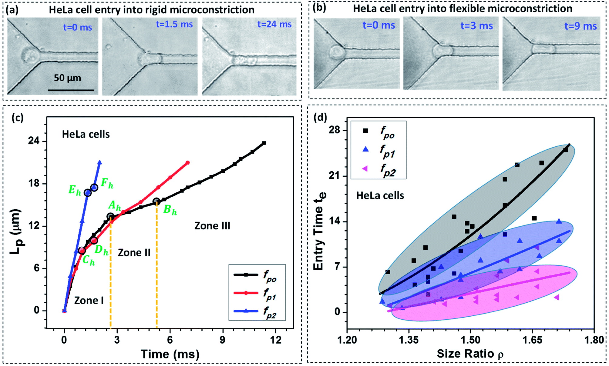 | ||
| Fig. 3 Microscopic images of a HeLa cell of diameter 18 ± 0.5 μm entering rigid (fp0) (a) and compliant (fp1 = 2.22 × 10⁻⁹ Pa−1) (b) micro-constrictions of hydraulic diameter 10.5 ± 0.25 μm, (c) variation in the protrusion length Lp of HeLa cells with time during entry into the micro-constriction for different compliance parameters (fp1 and fp2), (d) entry time of HeLa cells of varying size ratio ρ in rigid (fp0 = 0) and compliant channels, external applied pressure was maintained at 100 mbar, the solid lines represent the best fit of the experimental data. | ||
Fig. 3c shows the variation in the protrusion length Lp (ref. Fig. 1) of HeLa cells with time during their entry into the micro-constriction. The results for MDA-MB-231 cells are presented in Fig. S3 (a) in ESI.† As observed, the entry of a cell into a micro-constriction takes place over three successive regimes: protrusion and contact, squeeze and release.3,39 We have represented the transition points for different regimes using letters A to F with the suffix ‘h’ and ‘m’ for HeLa and MDA-MB-231 cells, respectively. The first regime between points O to A, O to C and O to E, represents the protrusion and contact regime for fp0, fp1 and fp2, respectively. In this regime, the cell first adjusts itself according to the micro-constriction size which is named as protrusion and then soon after, cell touches the channel walls, which is called contact. The slopes of the curves in this regime are equal for all compliance parameter values which indicates that in this regime the cell velocity is independent of the flexibility of the micro-constriction.
The second regime represents the squeeze, which is between points A to B, C to D and E to F for fp0, fp1 and fp2 respectively. In this regime, the cell deforms its whole body to move into the micro-constriction and hence the cell velocity in this regime is different according to the flexibility of the micro-constriction. As observed, the cell velocity is lowest in case of the rigid micro-constriction and is higher for a more compliant micro-constriction. So, the amount of time a cell spends in the squeeze regime is lesser for a micro-constriction of higher flexibility. We observe, in case of both cell lines, the width of the squeeze zone is maximum in case of fp0 and minimum in case of fp2. This phenomenon explains the observed decrement in the entry time te of a cell in compliant micro-constrictions as compared to that in rigid micro-constriction.
The third regime is represented beyond points B, D and F for fp0, fp1 and fp2 respectively in which the cell releases itself and accelerates to completely enter into the micro-constriction. In this regime, the cell further deforms its cytoskeleton thus allowing the leak flow around it and decreasing the viscous drag acting onto it which in turn increases the cell velocity. As observed, the increase in velocity (or acceleration) is higher in case of a more compliant micro-constriction which can be attributed to a higher decrement in the viscous drag in case of a more compliant channel due to larger leak-flow cross-sectional area around the cell.
Fig. 3d shows entry time of HeLa cell lines of varying size ratio ρ in rigid (fp0) and compliant channels for different compliance parameters (fp1 and fp2). The results for MDA-MB-231 cells are presented in Fig. S3(b) of the ESI.† For both the cell lines, in case of the rigid micro-constriction, the best fit lines (with R2 ≥ 0.65) shows that the entry time te increases exponentially with increase in the cell size following te ∼ e4.48ρ and te ∼ e4.32ρ for HeLa and MDA-MB-231 cell lines respectively. However, it is observed that in case of compliant micro-constriction, the entry time te increases linearly (with R2 ≥ 0.6) with the increase in the cell size ρ. This indicates that in case of compliant micro-constrictions, the entry time te becomes less sensitive to the increase in the size ratio ρ as compared to that in case of rigid constrictions. For both the cell lines, it is observed that for a fixed cell size ratio ρ, the entry time te is lesser in case of the compliant micro-constriction as compared to that in rigid micro-constriction. As observed, in case of both types of cells, as compared with the rigid micro-constrictions, the entry time decreases by one-half for fp1 and by one-fourth for fp2. This phenomenon can be attributed to the presence of a compliant membrane as one of the walls. When a cell starts entering into the compliant micro-constriction, the local pressure in the leak flow region between cell and compliant membrane increases which deforms the compliant membrane outward and compresses the cell allowing it to easily move into the micro-constriction. Thus as the flexibility of the membrane wall increases, the entry time of the cells becomes shorter.
The effect of stiffness of cells on the entry time is also compared (between HeLa and MDA-MB-231 cells) and the results are presented in Fig. S5 in ESI.† In our previous work,32 using Atomic Force Microscopy (AFM) technique, we have shown that the HeLa cell lines are stiffer than MDA-MB-231 cell lines. We observe that for a fixed cell size and compliance parameter (i.e. flexibility of the micro-constriction), the entry time is lesser for a less stiff cell line (i.e. MDA-MB-231 cell line). So the entry time te of a cell in a micro-constriction depends on the cell size and stiffness and the compliance parameter. Further, using a large set of experimental data, the best fit entry time te of the cells was correlated with Young's modulus of the cells Ec, compliance parameter of the micro-constriction fp and the cell size ratio ρ using Datafit software with a R2 value of 0.96 and a confidence interval of 99% as follows,
| te = m(ρ)k1(1 + fp)k2(Ec)k3 | (6) |
5.2 Cell passage through the micro-constriction
As discussed in Section 5.1, in case of a compliant micro-constriction, the membrane wall can undergo deformation thus allowing the cells to easily enter into the constriction. Here, we study the extension ratio λ (which is defined as the ratio of deformed length l to the undeformed diameter of the cell Dc) of cells during their passage through rigid (fp0) and compliant micro-constrictions (fp1 and fp2). Fig. 4a shows the variation of extension ratio λ with cell size ratio ρ for micro-constrictions of different compliance (fp0, fp1 and fp2) in case of HeLa cells. It is observed that at a fixed size ratio ρ, the extension ratio λ of cells through micro-constrictions decreases with increase in the compliance parameter. Also, the results show that the extension ratio λ is independent of the size ratio ρ at higher compliance parameter fp2. This is possibly due to the larger deformation of the membrane wall in the normal direction (to the plane of the constriction) which allows the cells of different size to also deform in this direction and migrate easily without undergoing any significant elongation.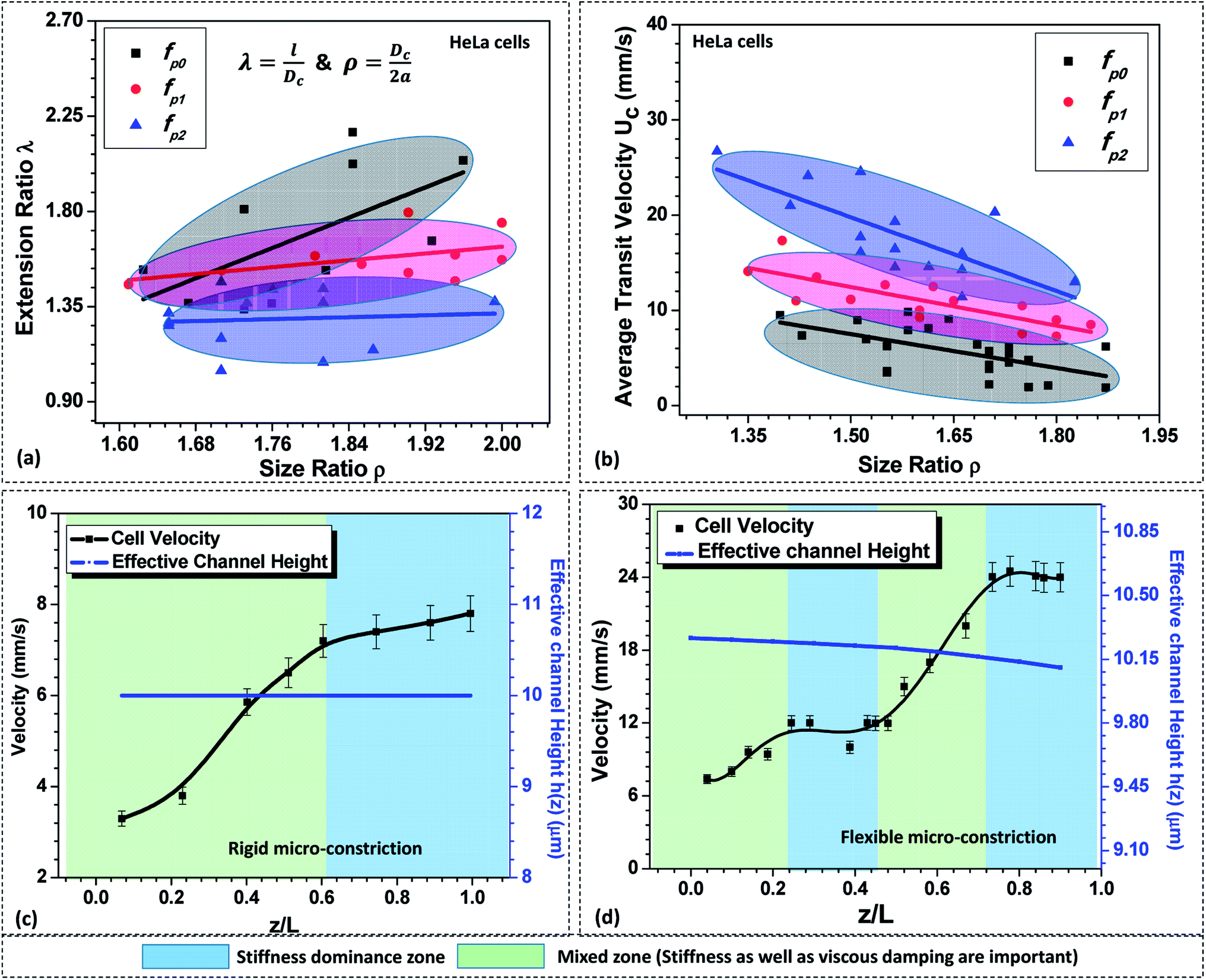 | ||
| Fig. 4 (a) Variation of extension ratio λ of the deformed HeLa cells while migrating through micro-constrictions of different flexibilities at z = 0.5L, (b) variation of average transit velocity with the compliance parameter fp. Variation in the local velocity of a HeLa cell of diameter 16 ± 0.5 μm through (c) rigid and (d) compliant micro-constrictions of hydraulic diameter 10.5 ± 0.25 μm, external pressure applied across the constriction was maintained to be 100 mbar. | ||
Next, we study the average transit velocity Uc of the cells (HeLa and MDA-MB-231) during their passage through rigid and compliant micro-constrictions. The average transit velocity Uc of a cell is defined as the ratio of the length of the microconstriction L to the total time the cell spends inside the constriction tm. The variation in the average transit velocity with size ratio of HeLa cells for micro-constrictions of different compliance (fp0, fp1 and fp2) is shown in Fig. 4b. The results for MDA-MB-231 cells are presented in Fig. S4(a) in ESI.† As observed, at a fixed size ratio, the transit velocity increases with increase in the compliance parameter. In case of HeLa cells, at ρ = 1.5, the transit velocity is three-time higher for compliance parameter fp2 and double in case of compliance parameter fp1 as compared to a rigid micro-constriction (fp0). This phenomenon can be explained as follows. The total force response from the cell, due to its stiffness Fs and the viscous damping effect Fd, is significantly dampened in case of compliant micro-constrictions as compared to rigid micro-constriction because of the ability of the compliant membrane wall to absorb the excess stress (due to its deformation). Moreover, the overall deformation of the cell reduces in the case of compliant micro-constriction as visible by the decreased extension ratio of the cell (see Fig. 4a) and causes a decrement in the surface area of the cell exposed to the flow. This reduces the net viscous drag on the cell surface and thus the average cell velocity is higher in case of compliant micro-constrictions as compared to rigid case for the same applied pressure gradient.
Further, the variation in the local velocity of the cells along the flow direction is studied in both rigid and compliant micro-constrictions and explained based on the Kelvin–Voigt viscoelastic solid model.37,38 Fig. 4c and d respectively show the variation in the local velocity of a HeLa cell of diameter 16 ± 0.5 μm through a micro-constriction of hydraulic diameter 10.5 ± 0.25 μm at an inlet pressure of 100 mbar. In the case of rigid micro-constriction, the effective hydraulic diameter 2a remains constant along the channel length which means that the cell does not encounter any change in the mechanical stimuli after entering the micro-constriction. Once cell has completely entered the micro-constriction, the cell initially accelerates up to z ∼ 0.5Lc but slows down further and attains a steady velocity. Thus, we observe two distinct zones in the velocity plot in case of cell passage through a rigid micro-constriction. According to Kelvin–Voigt viscoelastic model,37,38 the force response by a cell is contributed by stiffness as well as the internal viscosity of the cell. In the first zone, the force due to the cell stiffness Fs as well as that due to the viscous dampening Fd are significant and a combination of these two forces affect the motion of the cell. This results in an unsteady behavior of the cell and the cell velocity increases along the length of the micro-constriction. In the second zone, there is no further change in the deformation of the cell such that dδ/dt = 0 (see Section 3.2). Hence the force response due to the viscous dampening effect vanishes and only Fs affects the motion of the cell.
Now, as discussed in Section 3.1, in case of the case compliant micro-constriction, the deformation of the compliant membrane wall (channel) is dynamic while a cell migrates along its length. Since the confinement effect on the cell changes continuously during its passage, the cell deformation also changes dynamically resulting in dδ/dt ≠ 0. This gives rise to a non-zero value of the force response Fd due to the viscous dampening effect. It is observed that the cell undergoes acceleration and steady velocity zones in a periodic manner which is explained as follows. In the case of compliant micro-constriction, the overall channel hydraulic diameter is maximum at the inlet and slowly decreases to the nominal channel size at z = Lc. Once a cell enters the micro-constriction, it encounters the narrowing confinement due to which it slowly deforms its cytoskeletal structure and accelerates. However, after travelling some distance, it slows down and attains a steady velocity due to the excess drag force acting on the cell surface due to the narrow confinement. Then, once the cell modifies its shape, it accelerates again but slows down later to attain a steady velocity.
5.3 Induced hydrodynamic resistance of a cell migrating though a compliant constriction
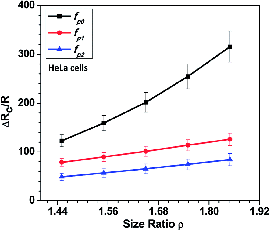
In this section, we present the induced hydrodynamic resistance of a single-cell during its passage through rigid and compliant micro-constrictions. Fig. 5 shows the variation in the induced hydrodynamic resistance ΔRc/R (predicted using eqn. (5)) of HeLa cell lines of size ratio ρ flowing through a micro-constriction of hydraulic diameter 10.5 ± 0.25 μm and different compliance (fp0, fp1 and fp2) at an inlet pressure of 100 mbar. The results for MDA-MB-231 cells are presented in Fig. S4(b) in ESI.† The results show that the induced hydrodynamic resistance increase with increase in the cell size ratio ρ which is due to higher drag force acting on the cell surface. For a fixed size ratio ρ, the induced hydrodynamic resistance ΔRc/R decreases with increase in the compliance parameter fp. At ρ = 1.85, the induced hydrodynamic resistance ΔRc/R decreases by four times for a compliant micro-constriction fp2 and three times for fp1 as compared to the rigid micro-constriction fp0. The decrease in the induced hydrodynamic resistance ΔRc/R with increase in the compliance parameter fp can be attributed to the decrease in the viscous drag acting on the cell surface with the increase in the flexibility of the micro-constriction. The induced hydrodynamic resistance is correlated using Datafit software (with R2 = 0.976 and confidence interval of 99%) with the size ratio ρ, cell's Young's modulus Ec and compliance parameter fp as follows,
 | (7) |
 | ||
| Fig. 5 Variation in the induced hydrodynamic resistance ΔRc/R (predicted using eqn. (5)) of HeLa cell with size ratio ρ flowing through micro-constrictions of different compliances (fp0, fp1 and fp2) at an inlet pressure of 100 mbar. | ||
The practical significance of the theoretical and experimental analysis presented in the current work is explained as follows. The experimental and theoretical approach is an effort to mimic the passage of cells (healthy or, diseased) through small micro-capillaries or, micropores. The ‘compliance parameter’ is representative of the stiffness of the capillary or micropore’. It was found, as the ‘compliance parameter’ decreases (i.e. the channel becomes stiffer), the entry and transit velocity of the cells also reduces and induced hydrodynamic resistance offered by them increases ultimately resulting in a higher pressure drop. The stiffening of blood vessels is often observed in case of various diseases such as atherosclerosis, hypertension, diabetes and coronary heart diseases, where the blood vessel gets occluded by the blood cells near the stenosis regions or, the micro-capillaries where the channel size is much smaller than the blood cell size. This gives rise to a higher pressure drop in the region of occlusion and thus disturbs the blood pressure effecting the healthy functioning of the body. Using the experimental and theoretical approach proposed by us, the phenomena can be quantitatively investigated invitro, for the understanding of such diseases.
6. Conclusion
Here, experimental and theoretical investigation of entry and passage behavior of biological cells (HeLa and MDA-MB-231) in a constricted compliant microchannel were reported. It was observed that the entry of a cell into a micro-constriction takes place over three successive regimes: protrusion and contact, squeeze and release. The results showed that the protrusion and contact regime is insensitive to the flexibility of the channel but the squeeze zone is significantly smaller in case of a more compliant channel. In the release zone, the cells accelerate into the micro-constriction and the acceleration was found to be higher in case of a more compliant channel. The overall entry time was found to be smaller for a more compliant micro-constriction. During the passage of cells in the constricted microchannel, the extension ratio λ and transit velocity Uc of the cells were studied. It was observed that for a fixed size ratio ρ and given cell, the extension ratio λ decreases and transit velocity Uc increases with increase in the compliance parameter fp. In case of a rigid channel, after entry, initially, acceleration of the cell in the micro-constriction was observed but later a steady velocity was observed. In case of a compliant micro-constriction, it was observed that acceleration and steady velocity zones occur repetitively. The force due to the cell stiffness Fs as well as that due to the viscous dampening Fd govern the variation in the cell velocity which was explained using the Kelvin–Voigt viscoelastic model. The theoretical model and experimental data were used determine the induced hydrodynamic resistance ΔRc of a single cell in a compliant constricted microchannel. The entry time te = m(ρ)k1(1 + fp)k2(Ec)k3 and induced hydrodynamic resistance of a cell ΔRc/R = k(ρ)a(1 + kffp)b(kEEc)c were correlated with cell size ratio ρ and Young's modulus Ec and compliance parameter fp. The correlations showed that both entry time te and the induced hydrodynamic resistance ΔRc are most sensitive to the change in the compliance parameter fp. The outcome of the studies reported here can significantly impact our understanding of passage of cells in soft confinements.Conflicts of interest
There are no conflicts to declare.Acknowledgements
This work was supported by the Science and Engineering Research Board (SERB) via project no. EMR/2014/001151, Department of Science and Technology (DST), India and IIT Madras via project no. MEE1516843RFTPASHS. The authors acknowledge the CNNP, IIT Madras for supporting the photolithography work.References
- R. Kamm, J. Lammerding and M. Mofrad, Springer Handb. Nanotechnol., 2010, 1171–1201 CrossRef.
- R. Kraemer, Vascular Biology, 2000, 2, 445–452 Search PubMed.
- M. Vicente-Manzanares, D. J. Webb and a R. Horwitz, J. Cell Sci., 2005, 118, 4917–4919 CrossRef PubMed.
- D. Huh, B. D. Matthews, A. Mammoto, M. Montoya-Zavala, H. Y. Hsin and D. E. Ingber, Science, 2010, 328, 1662–1668 CrossRef PubMed.
- B. S. Hardy, K. Uechi, J. Zhen and H. Pirouz Kavehpour, Lab Chip, 2009, 9, 935–938 RSC.
- R. N. Palchesko, L. Zhang, Y. Sun and A. W. Feinberg, PLoS One, 2012, 7(12), e51499 Search PubMed.
- Z. Wang, A. A. Volinsky and N. D. Gallant, J. Appl. Polym. Sci., 2014, 41050, 1–4 Search PubMed.
- J. W. Song, W. Gu, N. Futai, K. a. Warner, J. E. Nor and S. Takayama, Anal. Chem., 2005, 77, 3993–3999 CrossRef PubMed.
- P. J. Lee, P. J. Hung and L. P. Lee, Biotechnol. Bioeng., 2007, 97, 1340–1346 CrossRef PubMed.
- S. R. Khetani and S. N. Bhatia, Nat. Biotechnol., 2008, 26, 120–126 CrossRef PubMed.
- D. Huh, H. Fujioka, Y.-C. Tung, N. Futai, R. Paine, J. B. Grotberg and S. Takayama, Proc. Natl. Acad. Sci. U. S. A., 2007, 104, 18886–18891 CrossRef PubMed.
- K.-J. Jang and K.-Y. Suh, Lab Chip, 2010, 10, 36–42 RSC.
- A. Carraro, W. M. Hsu, K. M. Kulig, W. S. Cheung, M. L. Miller, E. J. Weinberg, E. F. Swart, M. Kaazempur-Mofrad, J. T. Borenstein, J. P. Vacanti and C. Neville, Biomed. Microdevices, 2008, 10, 795–805 CrossRef PubMed.
- R. Baudoin, L. Griscom, M. Monge, C. Legallais and E. Leclerc, Biotechnol. Prog., 2007, 23, 1245–1253 Search PubMed.
- M. Shin, K. Matsuda, O. Ishii, H. Terai, M. KaazempurMofrad, J. Borenstein, M. Detmar and J. P. Vacanti, Biomed. Microdevices, 2004, 269–278 CrossRef PubMed.
- J. P. Shelby, J. White, K. Ganesan, P. K. Rathod and D. T. Chiu, Proc. Natl. Acad. Sci. U. S. A., 2003, 100, 14618–14622 CrossRef PubMed.
- H. W. Hou, Q. S. Li, G. Y. H. Lee, A. P. Kumar, C. N. Ong and C. T. Lim, Biomed. Microdevices, 2009, 11, 557–564 CrossRef PubMed.
- M. J. Rosenbluth, A. Lam and D. A. Fletcher, Lab Chip, 2008, 8, 1062–1070 RSC.
- S. Byun, S. Son, D. Amodei, N. Cermak, J. Shaw, J. H. Kang, V. C. Hecht, M. M. Winslow, T. Jacks, P. Mallick and S. R. Manalis, Proc. Natl. Acad. Sci. U. S. A., 2013, 110, 7580–7585 CrossRef PubMed.
- K. D. Nyberg, M. B. Scott, S. L. Bruce, A. B. Gopinath, D. Bikos, T. G. Mason, J. W. Kim, H. S. Choi and A. C. Rowat, Lab Chip, 2016, 16, 3330–3339 RSC.
- A. Raj, M. Dixit, M. Doble and A. Sen, Lab Chip, 2017, 17, 3704–3716 RSC.
- A. Raj and A. K. Sen, Microfluid. Nanofluid., 2016, 20(31), 1–13 Search PubMed.
- D. J. Farrar, M. G. Bond, W. a. Riley and J. K. Sawyer, Circulation, 1991, 83, 1754–1763 CrossRef PubMed.
- T. Hirai, S. Sasayama, T. Kawasaki and S. Yagi, Circulation, 1989, 80, 78–86 CrossRef PubMed.
- S. Suresh, Acta Biomater., 2005, 1, 15–30 CrossRef PubMed.
- N. Walter, A. Micoulet, T. Seufferlein and J. P. Spatz, Biointerphases, 2011, 6, 117 CrossRef PubMed.
- Y. Zheng, H. Fujioka, S. Bian, Y. Torisawa, D. Huh, S. Takayama and B. J. Grotberg, Phys. Fluids, 2009, 21, 1–12 Search PubMed.
- M. J. Lighthill, J. Fluid Mech., 1968, 34, 113–143 CrossRef.
- J. M. Fitz-Gerald, Proc. R. Soc. London, Ser. B, 1969, 174, 193–227 CrossRef.
- A. Raj, R. Halder, P. Sajeesh and A. K. Sen, Microfluid. Nanofluid., 2016, 20, 1–16 CrossRef.
- P. Sajeesh, S. Manasi, M. Doble and A. K. Sen, Lab Chip, 2015, 15, 3738–3748 RSC.
- P. Sajeesh, A. Raj, M. Doble and A. K. Sen, RSC Adv., 2016, 6, 74704–74714 RSC.
- P. Sajeesh, M. Doble and A. K. Sen, Biomicrofluidics, 2014, 8, 054112 CrossRef PubMed.
- M. A. C. Ayala and R. Karnik, PhD Dissertation, MIT University, 2013.
- P. Sajeesh and A. K. Sen, PhD Dissertation, IIT Madras, 2015.
- F. Y. Leong, Q. Li, C. T. Lim and K. H. Chiam, Biomech. Model. Mechanobiol., 2011, 10, 755–766 CrossRef PubMed.
- E. A. Evans, Biophys. J., 1973, 13, 941–954 CrossRef PubMed.
- E. A. Evans and R. M. Hochmuth, Biophys. J., 1976, 16, 1–11 CrossRef PubMed.
- R. Horwitz and D. Webb, Curr. Biol., 2003, 13, 756–759 CrossRef.
Footnote |
| † Electronic supplementary information (ESI) available. See DOI: 10.1039/c8ra02763c |
| This journal is © The Royal Society of Chemistry 2018 |