 Open Access Article
Polyimide film with low thermal expansion and high transparency by self-enhancement of polyimide/SiC nanofibers net†
Feiyan Liua,
Zhihong Liua,
Shuyu Gaoa,
Qingliang Youab,
Liyong Zoua,
Jia Chena,
Jiyan Liu*ab and
Xueqing Liu *ab
*ab
aKey Laboratory of Optoelectronic Chemical Materials and Devices of Ministry of Education, China. E-mail: liujiyan918@163.com
bFlexible Display Materials and Technology Co-innovation Center of Hubei Province, School of Chemistry and Environmental Engineering, Jianghan University, Wuhan, China
First published on 23rd May 2018
Abstract
A facile approach to synthesize a polyimide (PI) film with enhanced dimensional stability, a high mechanical property and optical transparency is presented by embedding the partial imidized PI/SiC nanofiber-net in a poly(amic acid) (PAA) solution, followed by removing the solvent and imidization of the PAA. The nanofiber-network self-filled PI film demonstrates a much lower thermal expansion coefficient (CTE), an excellent mechanical property and high transparency retention in comparison to the film fabricated by solution cast. When the SiC content is 6 wt% in PI/SiC nanofibers, the CTE values for the PI film containing 25 wt% PI/SiC nanofibers are 2.80 times lower than the solution cast PI/SiC film. The tensile strength and modulus for the PI/SiC fiber filled film are also improved by 159% and 91% respectively in comparison to the solution cast SiC/PI film. In addition, the PI/SiC nanofiber-network filled PI film exhibits a high optic transparency. The significant improvement in aforementioned properties is contributed to by the long and continuous nanonetwork which acts as a frame to maintain the stable dimension and endow the film with high mechanical properties. Moreover, the nanosized SiC particles were constricted within the nano-fiber to avoid light scattering, so the high transparency of the film was retained.
1. Introduction
It is well known that materials will expand when they are heated and shrink when cooled. The linear thermal expansion coefficients (CTE) of polymers are in the range of 20–100 ppm °C−1, the CTE of metals are in the range of 3–20 ppm °C−1, and the CTE of ceramics are in the range of 3–5 ppm °C−1.1–3 Among these materials, the CTE values of polymers are the highest, which is due to the low energy barrier for conformation changes in molecular chains.4 Polyimides (PI) are a promising material in the semiconductor and microelectronic industries due to their excellent mechanical properties and outstanding thermal stability at elevated temperatures.5 PI is generally used as a coating material on silicon wafers as insulators or substrates of copper-clad laminates. These electronic devices usually serve in circumstances experiencing a wide temperature range. The mismatch in the CTE between the PI film and substrate will give rise to a thermal stress concentration, which leads to cracking or peeling of the PI film. When components' sizes become smaller and approach the nanoscale, subtle differences in the CTE critically affect the performance of the electronic system.6 Thus high performance PI films with a CTE less than 10 ppm °C−1 in the glassy temperature region are highly desirable for the applications discussed above.The most effective strategy to lower the CTE of polymers is the addition of ceramic fillers with low thermal expansion coefficients such as silica, mica, silicon nitride and so on.5–8 The size and morphology of the filler particles have a significant influence on the CTE values of the polymers.9–12 When micron-sized particles are added as fillers into polymers achieving a reduced CTE of 20–30 ppm °C−1 below Tg,13–17 high loading particles of 55–70% (by volume) are needed. The high loading filler usually leads to a high melting viscosity, unsatisfactory mechanical properties and poor transparency. When the filler sizes are reduced to the nanosize, much less filler loading is required to achieve the same CTE value.18–20 For example, adding 5 wt% of the well-dispersed nanosize silica reduced the CTE of PI by 40%,21 while the CTE of PI film was almost unchanged at the same filler loading when a microsize silica was added. Furthermore, many reports indicate that rod-like nanoparticles performed more effectively in CTE than spherical nanoparticles. Ozisik et al. reported that silica nanofiber filled epoxy showed a 1.4 times greater CTE compared to that of the spherical nanoparticle filled epoxy.18 Mallick et al. investigated the aspect ratio on the effective CTE of nanofiber reinforced epoxy.19 The result indicated that the CTE was reduced by 50% at 25 wt% of the filler loading when the aspect ratio of nanofibers increased from 10 to 100. Lots of experimentally and theoretically studies also demonstrated that continuous nanofibers or fillers possessing an aspect ratio of higher than 100 could achieve a low CTE.20–28
However, hetero nanofiber filled polymers are often confronted with the problem of high fiber debonding during composite fracture caused by the high interfacial area and poor adhesion between the fiber and the matrix.29–32 Nearly all the nanofibers need to be modified with coupling agents before blending with the polymer matrix, which may seriously affect the properties of the as-prepared nanocomposites. Using homogenous nanofibers has proved to be a good approach to improving the interface adhesion between matrix and fibers.33
Nonwoven PI nanofibers and single nanofibers possess superior mechanical properties compared with the neat solution cast PI film due to the molecular orientation of the polymer chains during electrospinning.34,35 High performance PI nanofiber self-reinforced composites demonstrated a variety of advantages such as transparency, being light-weight, and having a high mechanical performance.36,37
In this work, the PI/SiC nanonet obtained by electrospinning was used as homogenous filler to fabricate a PI film with a low thermal expansion coefficient. Also, the mechanical properties, transparency and heat-resistance were also investigated. The fabrication procedure is illustrated in Fig. S1.†
2. Experimental
2.1 Materials
p-Phenylene-diamine (PDD, 99%), 3,3′,4,4′-bi-phenyltetra carboxylic di-anhydride (BPDA, 98%), N-methyl-formamide (NMF) and N,N-dimethylacetamide (DMAc) were commercially obtained from China Medicine Co. Aniline and silicon carbide (SiC) were purchased from Sino pharm Chemical Reagent Co. Ltd. All other reactants were of analytical purity and used as received.2.2 Preparation of electrospinning solution
The precursor of polyimide, poly(amic acid) (PAA) was synthesized from BPDA and PDD with an equivalent molar ratio according to the following procedure. A three-necked flask equipped with mechanical stirring, thermometer and nitrogen inlet was purged with nitrogen for 15 min to remove the air, and was then charged with PDD (10.8140 g, 0.1 mol) and DMAc (120.7065 g). After the PDD had completely dissolved, BPDA powder (29.4215 g, 0.1 mol) was added. The stirring was continued at 50 °C for another 5 h to obtain the pristine PAA. The solid concentration of PAA was 25 wt%.The SiC nanoparticles were ultrasonically dispersed in DMAc for about 3 h. The SiC/DMAc solution was mixed with the pristine PAA solution at 30 °C under vigorous stirring. The solid concentration of PAA/SiC/DMAc solution was fixed at 17 wt% for electrospinning.
2.3 Electrospinning and imidization of nanofibers net
The solution was placed in a 10 mL syringe with a flattened metal spinneret having a diameter of 0.5 mm. Electrospinning was carried out with an applied voltage of 17 kV at 40 °C. The feeding rate was about 0.25 mL per hour. The fibers were collected on a square ITO glass of 10 cm on its side. During electrospinning, the linear speed of the rotating collector was about 20 m s−1. The distance between the spinneret and collector was 15 cm. The nanofibers were removed using solvent at 80 °C for 2 h and subsequently imidized following the program of 120 °C/1 h, 180 °C/1 h, 240 °C/1 h, 300 °C/1 h, 350 °C/1 h and 380 °C/0.5 h in nitrogen atmosphere with a heating rate of 5 °C min−1.2.4 Preparation of nanofiber reinforced PI films
The nanofiber reinforced PI film was fabricated by casting 17 wt% PAA of DMAc on to an as-prepared electrospun PI/SiC nanofiber net. The solution cast PI and PI/SiC film were fabricated by spin cast PAA or PAA/SiC solution onto glass substrates. They were both thermally imidized following the same temperature program as the nanofibers. All the resultant films were maintained at about 50 μm thickness to facilitate evaluation of the physical properties. Fig. S1† presents the schematic diagram for preparing the PI/SiC nanofiber reinforced film.2.5 Measurements and characterization
Measurement of the tensile property was carried out on a universal testing machine (CMT6000, SANS, Shenzhen, China) following the standard ASTMD 638. The testing speed was kept at 5 mm min−1. The morphology of the fracture surfaces of specimens subjected to tensile measurement were gold-coated and analyzed with a field emission scanning electron microscopy (FE-SEM) (Hitachi SU8010, Japan) connected to an energy dispersive X-ray spectrometry (EDS) analyzer (Apollo 40 SDD). The morphology of a single nanofiber was analyzed with transmission electron microscopy (TEM) (Hitachi, HT7800, Japan). Thermogravimetric analysis (TGA) was performed from 100 to 800 °C at a heating rate of 20 °C min −1 under a nitrogen flow (with a Waters SDT Q600, USA). Dynamic mechanical analysis (DMA) for the films was carried out from 30 to 450 °C at a heating rate of 5 °C min−1 under a nitrogen flow with a dynamic mechanical analyzer (TA Q-800, USA). The film was tested under the tensile mode at a frequency of 1 Hz. The thermal expansion along the plane (X–Y) direction of the film (15 mm long, 5 mm wide, and about 50 μm thickness) were measured at a heating rate of 5 °C min−1 with a thermomechanical analyzer (TA, TMA-400Q) in a dry nitrogen atmosphere. The CTE values of the films were obtained over the temperature range of 50–250 °C by averaging three test results.3. Results and discussion
3.1 Morphologies of PI/SiC nanofibers
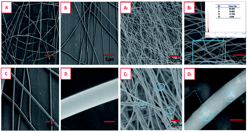
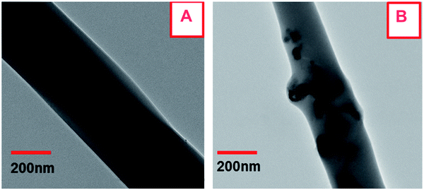
The quality of nanofiber is very important for achieving high strength and toughness. Fortunately, electrospun PI based nanofibers have been widely investigated. The electrospinning process can be tuned by altering the parameters such as the polymer concentration, applied electric field, spinneret-collector distance and flow rate of the feed solution to obtain the uniform, long, continuous nanofibers of desired diameter for further application in the reinforcement of PI films. Fig. 1 presents the SEM morphologies of the pure PI and PI/SiC nanofibers obtained under optimized experimental conditions. All of the nanofibers show a uniform dimension with about a 250 nm diameter. The surface of the PI fiber is smooth, for the PI/SiC nanofibers, most of SiC particles were embedded within the PI fibers, only a few particles are naked on the surface, as shown in Fig. 1C1. The SiC content in the nanofibers from EDX is close to the theoretical value. The morphologies of the nanofibers were obtained using TEM in Fig. 2 and indicated that the size of SiC aggregation inside the nanofiber is between 50–70 nm.3.2 Morphologies of films
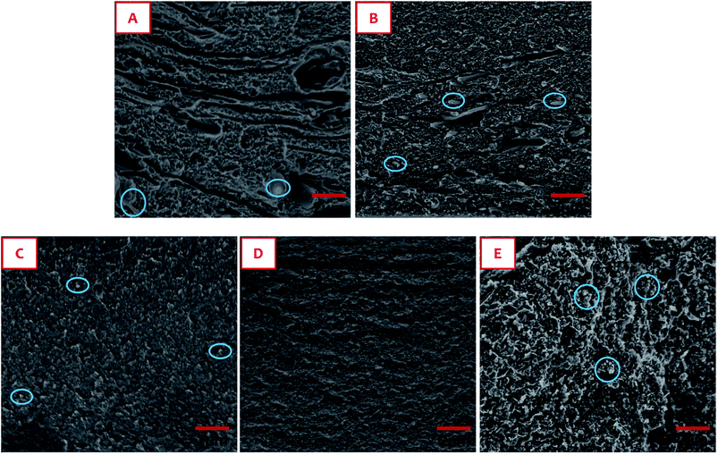
Fig. 3 shows the SEM morphologies of the fractured surfaces of films. The surface of the solution cast PI film (Fig. 3D) is homogeneous. For the PI nanofiber reinforced film (Fig. 3C), the surface is rough, white tips come out of the surface showing the presence of the embedded nanofibers, as marked in the blue circle. The nanofibers are intimately surrounded by the PI matrix and there is no crack between them. For the PI/SiC nanofiber filled film (Fig. 3A and B), there are caves and naked fibers on the surface. It is implied that some of the nanofibers were pulled out of the matrix when the film was broken. Apparently, the PI/SiC nanofibers exhibit inferior compatibility with the matrix in comparison to the PI nanofibers. The reason is that the naked SiC particles on the PI/SiC nanofibers have a poor adhesion to the matrix, which weakens the interface interaction and leads to the nanofibers easily peeling off the matrix. For the solution cast PI/SiC film (Fig. 2E), lots of particle aggregates are observed on the fracture surface, indicating poor dispersion of the particles in the matrix. In addition, the degree of imidization of nanofibers has an influence on the interaction between the nanofibers and the matrix. The degree of imidization of PAA has been comprehensively investigated.38–40 In our study, the dependence of the degree of imidization of the PAA on the temperature is presented in the Fig. S3.† The degree of imidization reaches 65% at 180 °C, and 100% of imidization is achieved at 380 °C.For the films obtained by casting the PAA pristine solution onto the PI/SiC nanofibers of 65% imidization (Fig. 3B), the nanofibers show better compatibility with the matrix in comparison to the film obtained by casting a pristine solution onto 100% imidized nanofibers (Fig. 3A). The reason is that the residual COOH/amide groups on the nanofibers can further react with the amide/COOH group of the matrix in the subsequent imidization of the film.
3.3 Transparency of the films
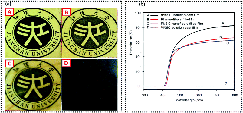
The UV-visible transmittance and digital photographs of the films covering words are presented in Fig. 4. The neat PI film obtained by conventional solution is yellowish and transparent with the transmittance of 83% at 600 nm. Nanofiber filled films show a slight reduction in transparency compared to the neat PI solution cast film. The transmittance is only reduced by 16.6% and 15.3% for the PI nanofiber filled film and the PI/SiC nanofiber filled film respectively, in comparison to the neat PI solution cast film. The words and pattern under the films are the clearly visible. However, the PI/SiC solution cast film is black and fully opaque. The above results indicate that the transparency of the film containing SiC nanoparticles can be efficiently retained when the particles were limited within the nanofibers. These isolated particles can avoid light scattering and thus a high retention of the optical transparency resulted for the PI/Si C nanofiber filled film.3.4 Mechanical performance of films
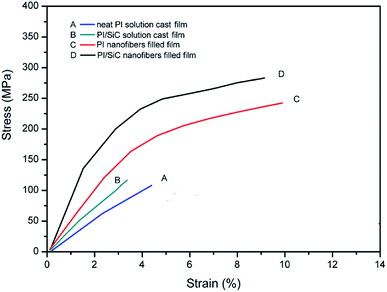
Stress–strain curves for the films are presented in Fig. 5. The tensile strength, tensile modulus and elongation at break were averaged and are listed in Table 1. The tensile strength and elongation at break for the nanofiber filled film are much higher than those of the solution cast film. In the case of the PI nanofiber filled film, the tensile strength, modulus and elongation at break were improved by 151.8%, 139% and 92.5%, respectively, in comparison to the pure PI solution cast film. For the PI/SiC nanofiber filled film, the tensile strength, modulus and the elongation at break are improved by 156.4%, 91.3% and 137%, respectively. The overall improvement in mechanical properties for the nanofiber filled films is ascribed to the enhancement of nanofibers filler and the good compatibility between the homogeneity filler and the matrix.| Samples | Tensile modulus/MPa | Elongation at break/% | Tensile strength/MPa | Tg/°C | CTE/ppm °C−1 |
|---|---|---|---|---|---|
| PI/SiC nanofiber filled film | 4221 ± 25 | 9.34 ± 0.25 | 283.4 ± 10.3 | 364.5 | 9.74 |
| PI nanofiber filled film | 3999 ± 30 | 9.91 ± 0.31 | 263.1 ± 11.2 | 357.2 | 15.24 |
| Solution cast PI/SiC film | 2207 ± 21 | 3.94 ± 0.14 | 110.5 ± 9.7 | 354.3 | 27.41 |
| Solution cast PI film | 1673 ± 19 | 4.85 ± 0.08 | 104.5 ± 8.5 | 350.7 | 35.9 |
The polymer chains within nanofibers are highly orientated, which endows the nanofibers with a high modulus and strength. These nanofibers act as a tough and strong frame undertaking the stress and resisting the deformation of the film. On the other hand, the good compatibility enhances the interfacial interaction between the PI matrix. The good adhesion of the interfaces is very important to achieving a high performance in mechanical properties.
Storage modulus and loss tangent (tan![[thin space (1/6-em)]](https://www.rsc.org/images/entities/char_2009.gif) δ) versus temperature curves for the films are shown in Fig. 6a and b respectively. The storage modulus is associated with the elastic response of the chain segments of the polymer, and can therefore give a better estimation of the nanofiber to matrix interaction. The increase in the storage modulus of the nanofiber filled film is because of the mechanical limitation posed by nanofibers in the matrix, thereby reducing the mobility and the deformation of the matrix. The tan
δ) versus temperature curves for the films are shown in Fig. 6a and b respectively. The storage modulus is associated with the elastic response of the chain segments of the polymer, and can therefore give a better estimation of the nanofiber to matrix interaction. The increase in the storage modulus of the nanofiber filled film is because of the mechanical limitation posed by nanofibers in the matrix, thereby reducing the mobility and the deformation of the matrix. The tan![[thin space (1/6-em)]](https://www.rsc.org/images/entities/char_2009.gif) δ intensity (the area under the β- and α-transition peak) in the Fig. 6b is a good indicator of the energy dissipation of the subchain and chains conformation being changed. A low tan
δ intensity (the area under the β- and α-transition peak) in the Fig. 6b is a good indicator of the energy dissipation of the subchain and chains conformation being changed. A low tan![[thin space (1/6-em)]](https://www.rsc.org/images/entities/char_2009.gif) δ intensity indicates less energy dissipation, due to a strong interaction force of molecular chains and rigidity of the chain.
δ intensity indicates less energy dissipation, due to a strong interaction force of molecular chains and rigidity of the chain.
In comparison to the solution cast PI film, the nanofiber filled films show a lower tan![[thin space (1/6-em)]](https://www.rsc.org/images/entities/char_2009.gif) δ intensity. One of the reasons is that highly oriented polymer chains within the nanofibers are close packing and difficult to move. On the other hand, the tan
δ intensity. One of the reasons is that highly oriented polymer chains within the nanofibers are close packing and difficult to move. On the other hand, the tan![[thin space (1/6-em)]](https://www.rsc.org/images/entities/char_2009.gif) δ, which shows differences in the viscoelastic response of the materials, is a ratio of the loss modulus to the storage modulus. The decreased value in tan
δ, which shows differences in the viscoelastic response of the materials, is a ratio of the loss modulus to the storage modulus. The decreased value in tan![[thin space (1/6-em)]](https://www.rsc.org/images/entities/char_2009.gif) δ indicates the fact that nanofiber filled films exhibit a more prominent elastic nature than a solution cast one. In addition, the glass transition temperature (Tg) of a nanofiber filled film is higher than the solution cast film. In Table 1, the Tg values of the PI nanofiber filled film and PI/SIC nanofiber filled film are increased by 6.7 °C, and 10.2 °C respectively, in comparison to the corresponding PI and PI/SIC film obtained by solution cast. The Tg is also associated with the mobility of the chain segment, the high Tg values for the nanofiber filled film further proved the good connection between the nanofibers and the matrix, as well as the restriction effect of the rigid nanofibers.
δ indicates the fact that nanofiber filled films exhibit a more prominent elastic nature than a solution cast one. In addition, the glass transition temperature (Tg) of a nanofiber filled film is higher than the solution cast film. In Table 1, the Tg values of the PI nanofiber filled film and PI/SIC nanofiber filled film are increased by 6.7 °C, and 10.2 °C respectively, in comparison to the corresponding PI and PI/SIC film obtained by solution cast. The Tg is also associated with the mobility of the chain segment, the high Tg values for the nanofiber filled film further proved the good connection between the nanofibers and the matrix, as well as the restriction effect of the rigid nanofibers.
3.5 CTE of the films
The dimension stability of the PI film in a wide temperature range is a very crucial property for their application in electric and electricity devices. Fig. 7a presents the dimension change of the film with the temperature. The slope of the curve is the linear CET. CTE values below 250 °C are listed in Table 1. It is noted that the CTE value of the PI film is starkly reduced by introducing the nanofibers. In the case of the PI nanofiber filled film, the CET value is 15.24 ppm °C−1, which is 2.32 times lower than that of the solution cast PI film (35.9 ppm °C−1); the CTE value of the PI/SiC nanofiber filled film is 9.74 ppm °C−1, 2.80 times lower than the solution cast PI/SiC film (27.41 ppm °C−1). The CTE of composites is associated with the expansion of the matrix, which is caused by the conformation change of the polymer chain. For the rigid particles or for fiber reinforced polymers, the CTE value is influenced by the number and size of the fillers, which constrain the deformation of the matrix. The amount of rigid fillers per unit volume increases tremendously with decreasing filler size (the number of fillers increased 109 times from micronsized fillers to nanosized fillers).41 Nanosize fillers have a greater specific area and provide a much larger interfacial region for constraining deformation of the polymer matrix by interfering with the thermal stress distribution inside the matrix during heating, as shown in Fig. 7b.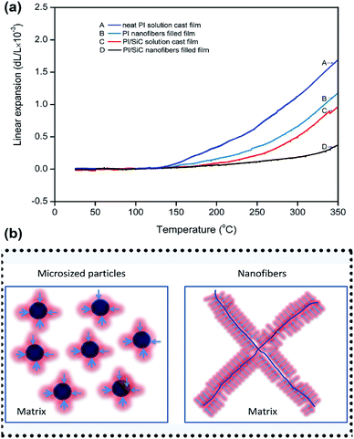 | ||
| Fig. 7 Linear expansion of the films with temperature (a) and representation of the constraining effect of nanofillers (b) on the PI matrix as depicted by the red shaded regions. | ||
4. Conclusion
In conclusion, the use of electrospinning technology opens up new opportunities for the processing of nanofibers and also gives the chance of dispersing the nanoparticles within the polymer in the nanoscale. Applying a continuous PI or PI hybrid nanofiber net to homogenously reinforce the PI film is an easy and efficient approach to fabricate the nanocomposites with high performance. Clearly, it has been shown that PI or PI hybrid nanofibers self-reinforced films exhibit a much lower CTE, higher transparency retention, and better mechanical and thermal properties in comparison to solution cast films. The main reason for the superior properties is obviously the excellent compatibility and chemical connection of the nanofibers with the matrix and the highly orientated and tough molecular chains in the long and continuous nanonet. Our study demonstrates a good example for fabricating high performance PI with a low CTE, high transparency and ultra-strong, tough mechanical properties by using this facile homogenous self-reinforcement method. These PI films with desirable properties could be promising candidates for advanced electrical or electrochemical devices and optoelectronic engineering materials.Conflicts of interest
There are no conflicts to declare.Acknowledgements
This work is supported by the National key research and development (R&D) program of China (Grant No. 2016YFB0401505) and the “Chutian Scholar Program” of Hubei province.Notes and references
- J. Brandrup, E. H. Immergut and E. A. Grulke, Carbohydrate polymers, Polymer Handbook, 2001, vol. 46, p. 295 Search PubMed.
- R. C. Weast, Handbook of chemistry and physics, CRC Press, Boa Raton, FL, 1977 Search PubMed.
- D. Green, An introduction to the mechanical properties of ceramics, Cambridge University Press, Cambridge, U.K., 2004 Search PubMed.
- R. F. Boyer and R. S. Spencer, J. Appl. Phys., 1944, 15, 398–405 CrossRef.
- D. J. Liaw, K. L. Wang, Y. C. Huang, L. R. Lee, J. Y. Lee, J. Y. Lai and C. S. Ha, Prog. Polym. Sci., 2012, 37, 907–974 CrossRef.
- M. Hasegawa, T. Kaneki, M. Tsukui, N. Okubo and J. Ishii, Polymer, 2016, 99, 292–306 CrossRef.
- Y. U. Juan, Y. Jiang, Z. Que, X. Wang and P. Huang, Mater. Rev., 2009, 23, 58–60 Search PubMed.
- X. W. Shi, H. Lian, X. S. Yan, R. Qi, N. Yao and T. Li, Mater. Chem. Phys., 2016, 179, 72–79 CrossRef.
- Y. C. Chen, H. C. Lin and Y. D. Lee, J. Polym. Res., 2003, 10, 247–258 CrossRef.
- V. I. Vettegren, A. Y. Bashkarev and M. A. Suslov, Tech. Phys., 2007, 52, 1383–1386 CrossRef.
- K. Takenaka, Sci. Technol. Adv. Mater., 2012, 13, 013001 CrossRef PubMed.
- Y. Nakamura, M. Yamaguchi and M. Okubo, J. Appl. Polym. Sci., 2010, 44, 151–158 CrossRef.
- K. H. Nam, S. Kim, J. Song and H. Hao, Macromol. Res., 2016, 24, 104–113 CrossRef.
- Y. Q. Rao and T. N. Blanton, Macromolecules, 2007, 41, 935–941 CrossRef.
- L. C. Kozy, M. N. Tahir, C. Lind and W. Tremel, J. Mater. Chem., 2009, 19, 2760–2765 RSC.
- V. P. Baradkar and S. Kumar, Polymer, 2001, 42, 879–888 CrossRef.
- T. S. Chow, J. Polym. Sci., Polym. Phys. Ed., 1978, 16, 967–970 CrossRef.
- L. Y. Ren, K. Pashayi, H. R. Fard, S. P. Kotha, T. B. Tasciuc and R. Ozisik, Composites, Part B, 2014, 66, 228–234 CrossRef.
- K. Mallick, J. Cronin and S. Arzberger, Aiaa/asme/asce/ahs/asc Structures, Structural Dynamics, and Materials Conference, Aiaa/asme/ahs Adaptive Structures Conference, 2006, vol. 143, pp. 1287–1293 Search PubMed.
- J. W. Zha, L. Jing, T. Zhou, J. K. Yuan and Z. M. Dang, J. Adv. Phys., 2012, 1, 48–53 CrossRef.
- J. C. Tang, G. L. Lin, H. C. Yang, G. J. Jiang and Y. W. Chen-Yang, J. Appl. Polym. Sci., 2010, 104, 4096–4105 CrossRef.
- C. P. Wong and R. S. Bollampally, J. Appl. Polym. Sci., 2015, 74, 3396–3403 CrossRef.
- A. A. Fahmy and A. N. Ragai, J. Appl. Phys., 1970, 41, 5108–5111 CrossRef.
- M. K. Hassanzadeh-Aghdam, R. Ansari and A. Darvizeh, Composites, Part A, 2017, 96, 110–121 CrossRef.
- K. Y. Lee, K. H. Kim, S. K. Jeoung, N. H. Kim, S. G. Lee and D. R. Paul, Polymer, 2007, 48, 4174–4183 CrossRef.
- J. M. Jung, H. Y. Ji, H. J. Jeong and H. S. Kim, Metall. Mater. Trans. A, 2014, 45, 5679–5690 CrossRef.
- D. W. Abueidda, A. S. Dalaq, R. K. A. Al-Rub and I. Jasiuk, Compos. Struct., 2015, 133, 85–97 CrossRef.
- C. J. Halpin, J. Compos. Mater., 1969, 3, 732–734 CrossRef.
- Q. Wu, K. Chi, Y. Wu and S. Lee, Mater. Des., 2014, 60, 334–342 CrossRef.
- A. Gu and F. Chang, J. Appl. Polym. Sci., 2015, 79, 289–294 CrossRef.
- G. Wang, D. Yu, A. D. Kelkar and L. Zhang, Prog. Polym. Sci., 2017, 75, 73–107 CrossRef.
- Y. Ding, H. Hou, Y. Zhao and F. Hao, Prog. Polym. Sci., 2016, 61, 67–103 CrossRef.
- S. Mohammadzadehmoghadam, Y. Dong and J. I. Davies, J. Polym. Sci., Part B: Polym. Phys., 2015, 53, 1171–1212 CrossRef.
- C. B. Huang, S. Q. Wang, H. A. Zhang, T. T. Li, S. L. Chen, C. L. Lai and H. Q. Hou, Eur. Polym. J., 2006, 42, 1099–1104 CrossRef.
- G. C. Zhong and Q. Jiang, J. Phys. D: Appl. Phys., 2008, 41, 369–374 Search PubMed.
- D. Chen, R. Wang, W. T. Weng and T. Liu, Compos. Sci. Technol., 2011, 71, 1556–1562 CrossRef.
- S. Jiang, G. Duan, J. Schobei, S. Agarwal and A. Greiner, Compos. Sci. Technol., 2013, 88, 57–61 CrossRef.
- O. Yucel, E. Unsal, J. Harvey, M. Graham, D. H. Jones and M. Cakmak, J. Membr. Sci., 2015, 495, 65–71 CrossRef.
- D. Ryan, L. Mulrane, E. Rexhepaj and W. M. Gallagher, Macromolecules, 1989, 22, 4166–4172 CrossRef.
- Y. Zhai, Q. Yang, R. Zhu and Y. Gu, J. Mater. Sci., 2008, 43, 338–344 CrossRef.
- L. Ren, K. Pashayi and H. R. Fard, Composites, Part B, 2014, 58, 228–234 CrossRef.
Footnote |
| † Electronic supplementary information (ESI) available. See DOI: 10.1039/c8ra02479k |
| This journal is © The Royal Society of Chemistry 2018 |

