 Open Access Article
Effects of area, aspect ratio and orientation of rectangular nanohole on the tensile strength of defective graphene – a molecular dynamics study
Xinmao Qin *a,
Wanjun Yana,
Xiaotian Guo
 b and
Tinghong Gaoc
aSchool of Electronic and Information Engineering, Anshun University, Anshun, 561000, China. E-mail: qxm200711@126.com
bSchool of Mathematics and Physics, Anshun University, Anshun, 561000, China
cCollege of Big Data and Information Engineering, Guizhou University, Guiyang, 550025, China
First published on 9th May 2018
Abstract
Molecular dynamics simulations with adaptive intermolecular reactive empirical bond order (AIREBO) potential are performed to investigate the effects of rectangular nanoholes with different areas, aspect ratios (length/width ratios) and orientations on the tensile strength of defective graphene. The simulations reveal that variation of area, aspect ratio and orientation of rectangular nanohole can significantly affect the tensile strength of defective graphene. For example, defective graphene with a larger area of rectangular nanohole shows a bigger drop in tensile strength. It was found that the tensile strength of both armchair and zigzag edged graphene monotonically decreases with area increases in rectangular nanohole. Changes in aspect ratio and orientation of rectangular nanohole, however, can either decrease or increase the tensile strength of defective graphene, dependent on the tensile direction. This study also presents information that the tensile strength of defective graphene with large area of nanohole is more sensitive to changes in aspect ratio and orientation than is defective graphene with small area of nanohole. Interestingly, variation of tensile strength of defective graphene from MD simulations is in good agreement with predictions from energy-based quantized fracture mechanics (QFM). The present results suggest that the effect of nanoholes on the tensile strength of graphene provides essential information for predictive optimization of mechanical properties and controllable structural modification of graphene through defect engineering.
1. Introduction
Graphene is a two-dimensional single atomic layer material, which consists of carbon atoms packed in a honeycomb structure.1 Its extraordinary geometric and electronic structure afford graphene excellent physical, chemical and mechanical properties,2–5 such as high carrier mobility, large specific surface area, high fracture intrinsic strength and elastic modulus. Such properties make graphene suitable for applications in various fields, for example, in nanocomposites,6 chemical sensors,7 supercapacitors,8 lithium-ion batteries,9 DNA-sequencing tools10 and selective molecular sieving devices.11 However, the inadvertent introduction of various topological defects (vacancy, substitutional atom, adatom, Stone–Thrower–Wales defect, dislocation and grain boundary) and other large-sized defects (nanopore, nanocrack and nanohole) is unavoidable in the process of preparation and manipulation of graphene-based devices.12 In addition, such defects can also occur as a result of the conditions in which graphene-based devices are used,13 and previous study has shown that structural defects in a graphene sheet have great influence on its properties.14,15 For example, a vacancy defect can significantly decrease the fracture strength and Young's modulus of graphene sheet, and the Young's modulus stabilization after reconstruction of the vacancy defect.16,17 The Young's modulus of a nitrogen-doped graphene sheet is independent of the concentration of nitrogen, but silicon-doped graphene shows a notable weakening in its Young's modulus.18 The tensile strength of graphene decreases markedly with increase in the number of substitutional nitrogen and silicon atoms, and then the fracture behavior of graphene transforms from ductile to brittle.13,19 Pei20 and co-workers found that adsorption of hydrogen on a graphene sheet can drastically deteriorate its Young's modulus, failure strength and fracture strain. They further investigated the mechanical properties of methyl (CH3) functionalized graphene, and found that these are dependent on the position, distribution and coverage of CH3 radicals on graphene.21 The effects of Stone–Thrower–Wales (STW) defect, grain boundaries (GBs) and dislocation on the mechanical properties of the graphene sheet were researched based on molecular dynamics simulations. Different types of STW defect have different effects on the mechanical properties of graphene sheet.22,23 When there is more than one STW defect, the fracture strength of graphene is affected by the orientation of the multiple defects.24 Successful preparation of polycrystalline graphene is necessary to study the relationships between the structure of grain boundaries of polycrystalline graphene and its mechanical properties. Wei25 and Han26 reported that grain boundary defects can either increase or decrease the fracture strength of graphene, dependent on the specific arrangement of the defects, not just their concentration. Meng27 et al. presented a comprehensive study of the dependency between the nanocrack and dislocation in graphene sheet, identifying that dislocation in graphene will shield the process of nanocrack propagation. Except for the topological defects, the influence of large sized defects (nanopore, nanocrack) on graphene sheet has been explored. After studying the mechanical properties of graphene with various shapes, sizes and density of nanopore, Liu28 and David29 concluded that the tensile strength of graphene decreases with increasing size and density of nanopore. Zhang30 and Zhao31 found that the fracture strength of graphene declines as the length of nanocrack increases, and Le and Batra32–35 further reported the effects of crack length on the crack propagation rate and the fracture behavior.In summary, the appearance of defects in graphene can weaken its mechanical properties, such as fracture strength, Young's modulus and fracture strain. However, such defects have potential in novel applications of graphene, for example, as molecule capacitors and nanofilters. Unfortunately, there are very few studies on the effects of large sized rectangular nanoholes with different characteristics on the mechanical properties of graphene, and such study is necessary for further applied research of graphene-based nanocomposites and nanosensors.
In the current study, molecular dynamics simulations were performed using LAMMPS (Large-scale Atomic/Molecular Massively Parallel Simulator)36,37 with the adaptive intermolecular reactive empirical bond order (AIREBO) potential. Systematic investigations were made into the effects of rectangular nanoholes of various areas, aspect ratios (length/width ratio) and orientations on the tensile strength of defective graphene. It was found that the tensile strength of both armchair and zigzag edged graphene monotonically decreases with area increases of nanohole. With changes of aspect ratio and orientation of rectangular nanohole, however, the defect can either decrease or increase the tensile strength of defective graphene, dependent on the tensile direction. It is also suggested that the tensile strength of defective graphene with large area of nanohole is more sensitive to changes in aspect ratio and orientation than is defective graphene with small area of nanohole. The current findings will provide a useful guideline for designing mechanically robust graphene-enhanced nanocomposites and graphene-based devices, such as nanosensors, DNA-sequencing tools and selective molecular sieving devices.
2. Simulation conditions and methods
2.1 Initial conditions
The tensile model of the graphene sheet consisted of 3807 carbon atoms, with zigzag and armchair edges of 10 nm. The center of the graphene sheet was located at the origin of the coordinate system, and the zigzag and armchair edges were parallel to the x and y directions, respectively. This means that the process of loading in the x(y) direction is the tensile deformation along the zigzag (armchair) graphene sheet (Fig. 1(a) and (b)). By deleting specified carbon atoms at the centered region of the graphene sheet, models of rectangular nanohole with different areas, aspect ratios and orientations were created. In the simulation, the areas of rectangular nanohole are 1 nm2, 2 nm2, 4 nm2 and 6 nm2, respectively. a/b is defined as the aspect ratio of rectangular nanohole, and the aspect ratio of rectangular nanohole is equal to 2![[thin space (1/6-em)]](https://www.rsc.org/images/entities/char_2009.gif) :
:![[thin space (1/6-em)]](https://www.rsc.org/images/entities/char_2009.gif) 1, 3
1, 3![[thin space (1/6-em)]](https://www.rsc.org/images/entities/char_2009.gif) :
:![[thin space (1/6-em)]](https://www.rsc.org/images/entities/char_2009.gif) 1 and 4
1 and 4![[thin space (1/6-em)]](https://www.rsc.org/images/entities/char_2009.gif) :
:![[thin space (1/6-em)]](https://www.rsc.org/images/entities/char_2009.gif) 1, respectively. The orientation of the nanohole is further defined as the tilting angle (θ), and this angle is between the direction of the “a” axis of rectangular nanohole and the zigzag direction of the graphene sheet (Fig. 1). When θ = 0°, the “a” axis of nanohole parallels the zigzag direction (Fig. 1(c) and (d)), when θ = 90°, the “a” axis is perpendicular to the zigzag direction of the graphene sheet (Fig. 1(e) and (f)).
1, respectively. The orientation of the nanohole is further defined as the tilting angle (θ), and this angle is between the direction of the “a” axis of rectangular nanohole and the zigzag direction of the graphene sheet (Fig. 1). When θ = 0°, the “a” axis of nanohole parallels the zigzag direction (Fig. 1(c) and (d)), when θ = 90°, the “a” axis is perpendicular to the zigzag direction of the graphene sheet (Fig. 1(e) and (f)).
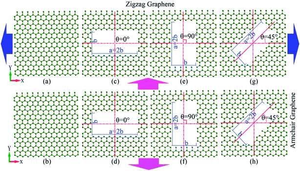 | ||
| Fig. 1 Models of tensile deformation of pristine graphene or defective graphene with rectangular nanohole. | ||
Periodic boundary conditions were applied in all directions. Using the steepest descent algorithm, energy minimization configurations of the system were performed by iteratively adjusting the coordinates of the carbon atoms of the graphene. Prior to tensile deformation, the tensile model was relaxed at 300 K and 0 bar pressure through an isothermal–isobaric ensemble (NPT) for 10 ps. All the tensile deformations of graphene are carried out at a constant temperature of 300 K, which was realized using a Nose–Hoover thermostat.38–41 Uniaxial tensile loading with a strain rate of 0.005 ps−1 was applied to the x or y directions of graphene, with simulation timestep of 0.001 ps. To analyze the behavior of fracture of defective graphene, the atomic configuration was visualized and the stress distributions of carbon atoms were determined using OVITO42 (The Open Visualization Tool), an open source visualization tool for molecular dynamics simulation. The tensile strength of defective graphene is defined as the point at which the maximum stress is reached. To obtain the stress–strain curve, the thickness of the graphene sheet was first defined as 3.4 Å.
2.2 Potential between atoms
The C–C interatomic interactions in graphene were calculated using adaptive intermolecular reactive empirical bond order (AIREBO) potential,36 which has been extensively used to simulate the mechanical properties of graphene. This potential enables the breaking and creation of covalent bonds, and has been successfully applied in studies of the properties of carbon-based nanomaterials.37 The AIREBO potential consists of three terms:
 | (1) |
3. Results and discussions
To search for reasonable strain rate of the graphene sheet, tensile deformations with various loading rates were performed using the LAMMPS package. Fig. 2 shows variation of tensile strength (zigzag direction, armchair direction, the average strength of the zigzag and armchair directions) of pristine graphene with strain rate from 5 × 10⁻⁵ ps−1 to 5 × 10⁻² ps−1. From Fig. 2, it can be concluded that the tensile strength increases with the strain rate. As the strain rate ranges from 5 × 10⁻⁵ ps−1 to 5 × 10⁻² ps−1, the strength gap between zigzag and armchair graphene gets smaller and smaller. When the strain rate is 1 × 10⁻² ps−1 (and 5 × 10⁻² ps−1), the strength of zigzag graphene is almost equal to that of armchair graphene. Fig. 2 also shows the comparison of tensile strength (zigzag direction, armchair direction, the averaged strength among the zigzag and armchair direction) between the present work and results from the study described in ref. 23 (with temperature and strain rate of tensile deformation being 300 K and 5 × 10⁻³ ps−1, respectively). Thus, the tensile strength of the present research is in accordance with the results from ref. 23. Consequently, the strain rate of 5 × 10⁻³ ps−1 was applied in the present tensile deformation.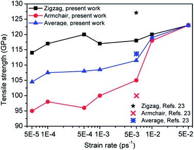 | ||
| Fig. 2 Effects of strain rate on tensile strength of pristine graphene in the present work, and the comparison of tensile strength between the present work and ref. 23 (strain rate of 5 × 10⁻³ ps−1). | ||
To further validate the proposed computational method and model, a comparison of mechanical properties between the present study (strain rate of 5 × 10⁻³ ps−1 and temperature of 300 K) and those from the literature is shown in Table 1. The calculated tensile strengths of pristine zigzag and armchair graphene are about 118 GPa and 105 GPa, respectively. The computed Young's modulus and tensile strength, averaged among the zigzag and armchair graphene sheet, are 0.83 TPa and 114 GPa, respectively, and the tensile strains of zigzag and armchair graphene sheet are 0.32 and 0.24, respectively. There is no large difference between the present results and those from the literature.3–5,20,23,35
| Eaverage (TPa) | σaverage (GPa) | σzig (GPa) | σarm (GPa) | εzig | εarm | |
|---|---|---|---|---|---|---|
| Experiment3 | 1.0 | 123.5 | — | — | — | — |
| DFT4 | — | — | 121 | 110 | 0.266 | 0.194 |
| MD & orthogonal tight-binding (TB) method (300 K)5 | 1.03 ± 0.03 | 115.5 | 129 | 102 | 0.2 | 0.13 |
| MD (300 K)20 | 0.86 | 121 | 137 | 105 | 0.27 | 0.17 |
| MD (300 K)23 | — | 113 | 126 | 100 | 0.22 | 0.13 |
| MD (0 K)35 | 1.04 | 118.5 | 126 | 111 | 0.238 | 0.191 |
| Present work (300 K) | 0.83 | 114 | 118 | 105 | 0.32 | 0.24 |
3.1 Effects of area of rectangular nanohole on the tensile strength of graphene sheet
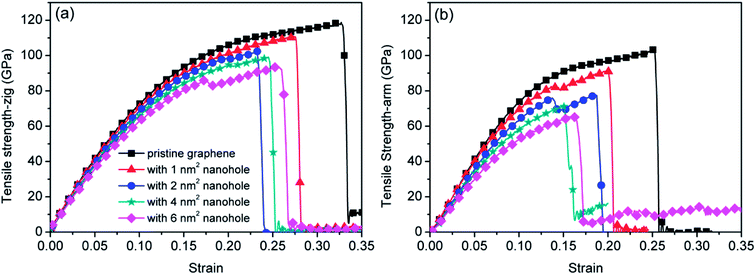
To study the effects of the areas of nanohole on the tensile strength of graphene sheet, defective graphene—with rectangular nanohole of four area types—was loaded in the zigzag and armchair directions, respectively. Fig. 3 shows the stress–strain curves of pristine graphene and defective graphene with areas of 1 nm2, 2 nm2, 4 nm2 and 6 nm2 nanohole (with aspect ratio and tilting angle of nanohole maintained at 2![[thin space (1/6-em)]](https://www.rsc.org/images/entities/char_2009.gif) :
:![[thin space (1/6-em)]](https://www.rsc.org/images/entities/char_2009.gif) 1 and 0°, respectively). The tensile strength of defective graphene decreases with increasing area of nanohole.
1 and 0°, respectively). The tensile strength of defective graphene decreases with increasing area of nanohole.
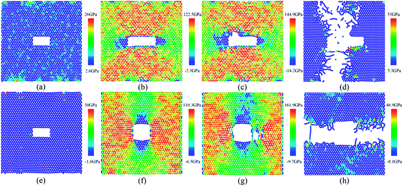
To understand the mechanism of fracture of the defective graphene, snapshots of the tensile deformation process of graphene with the area of 2 nm2 nanohole are shown in Fig. 4 (with aspect ratio and tilting angle of nanohole maintained at 2![[thin space (1/6-em)]](https://www.rsc.org/images/entities/char_2009.gif) :
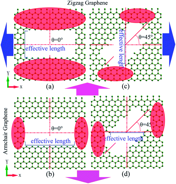
:![[thin space (1/6-em)]](https://www.rsc.org/images/entities/char_2009.gif) 1 and 0°, respectively). The von Mises stress of the graphene is calculated, and the stress distribution is plotted by the color contour in the figures. At the beginning of the tensile deformation, the stress of carbon atoms is maintained at a relatively low level (Fig. 4(a) and (e)). With increasing tensile deformation (the Fig. 4(b) and 4(f)), the atomic stress is considerably increased, and there is obvious stress concentration present at the local region of defective graphene (Fig. 4(b), the up and down red region of defective graphene; Fig. 4(f), the left and right red region of defective graphene). There is then nanocrack formation and gradual growth at the local high-stress region (Fig. 4(c), the left-up position; Fig. 4(g), the right-middle position). Subsequently, fracture of the defective graphene sheet occurs at the local region of stress concentration (Fig. 4(d) and (h)). From Fig. 4, the regions of stress concentrations of defective graphene were located at the up and down region of defective graphene for the zigzag deformation (or at the left and right region for the armchair deformation). The region of stress concentration, termed the “effective loading area” (the red region in Fig. 4), clearly affected the tensile strength of defective graphene.
1 and 0°, respectively). The von Mises stress of the graphene is calculated, and the stress distribution is plotted by the color contour in the figures. At the beginning of the tensile deformation, the stress of carbon atoms is maintained at a relatively low level (Fig. 4(a) and (e)). With increasing tensile deformation (the Fig. 4(b) and 4(f)), the atomic stress is considerably increased, and there is obvious stress concentration present at the local region of defective graphene (Fig. 4(b), the up and down red region of defective graphene; Fig. 4(f), the left and right red region of defective graphene). There is then nanocrack formation and gradual growth at the local high-stress region (Fig. 4(c), the left-up position; Fig. 4(g), the right-middle position). Subsequently, fracture of the defective graphene sheet occurs at the local region of stress concentration (Fig. 4(d) and (h)). From Fig. 4, the regions of stress concentrations of defective graphene were located at the up and down region of defective graphene for the zigzag deformation (or at the left and right region for the armchair deformation). The region of stress concentration, termed the “effective loading area” (the red region in Fig. 4), clearly affected the tensile strength of defective graphene.
3.2 Effect of aspect ratio of rectangular nanohole on the tensile strength of graphene sheet
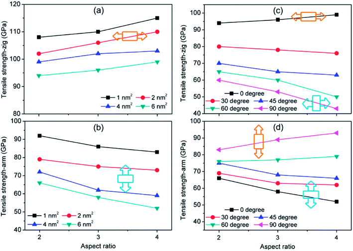
Fig. 5 shows the dependence of tensile strength of defective graphene on the aspect ratio of rectangular nanohole at different areas and tilting angles. When the tilting angle of rectangular nanohole is 0° (the orange and deep skyblue insets in Fig. 5(a) and (b)), no matter the area of nanohole, the tensile strength of zigzag (armchair) defective graphene sheet increases (decreases) with aspect ratio from 2![[thin space (1/6-em)]](https://www.rsc.org/images/entities/char_2009.gif) :
:![[thin space (1/6-em)]](https://www.rsc.org/images/entities/char_2009.gif) 1 to 3
1 to 3![[thin space (1/6-em)]](https://www.rsc.org/images/entities/char_2009.gif) :
:![[thin space (1/6-em)]](https://www.rsc.org/images/entities/char_2009.gif) 1 to 4
1 to 4![[thin space (1/6-em)]](https://www.rsc.org/images/entities/char_2009.gif) :
:![[thin space (1/6-em)]](https://www.rsc.org/images/entities/char_2009.gif) 1 (Fig. 5(a) and (b)). For different areas of rectangular nanohole, with the increasing aspect ratio, the variation in tensile strength is similar. From Fig. 5(c) and (d), it can be seen that the slope of tensile strength versus aspect ratio curves changes with tilting angle of rectangular nanohole (with the area of nanohole maintained at 6 nm2). When the tilting angle is 0°, the strength of zigzag (armchair) defective graphene relatively increases (decreases); but as the tilting angle moves to 60°, the strength of zigzag (armchair) defective graphene slightly decreases (increases); finally, when the tilting angle is 90°, the variations of strength of defective graphene with aspect ratio of rectangular nanohole become obvious (the tensile strength of zigzag and armchair defective graphene become small and large, respectively). Comparing the variation tendency of tensile strength (the curves of Fig. 5) and the tensile model (the insets of Fig. 5) of defective graphene sheet, it was found that the tensile strength increases as the aspect ratio increases, with the direction of the long axis (“a” axis in Fig. 1) of rectangular nanohole parallel to the tensile direction of defective graphene sheet (the orange insets in Fig. 5). For the direction of the long axis of rectangular nanohole perpendicular to the tensile direction of defective graphene sheet, however, the tensile strength decreases as the aspect ratio increases (the deep skyblue insets in Fig. 5).
1 (Fig. 5(a) and (b)). For different areas of rectangular nanohole, with the increasing aspect ratio, the variation in tensile strength is similar. From Fig. 5(c) and (d), it can be seen that the slope of tensile strength versus aspect ratio curves changes with tilting angle of rectangular nanohole (with the area of nanohole maintained at 6 nm2). When the tilting angle is 0°, the strength of zigzag (armchair) defective graphene relatively increases (decreases); but as the tilting angle moves to 60°, the strength of zigzag (armchair) defective graphene slightly decreases (increases); finally, when the tilting angle is 90°, the variations of strength of defective graphene with aspect ratio of rectangular nanohole become obvious (the tensile strength of zigzag and armchair defective graphene become small and large, respectively). Comparing the variation tendency of tensile strength (the curves of Fig. 5) and the tensile model (the insets of Fig. 5) of defective graphene sheet, it was found that the tensile strength increases as the aspect ratio increases, with the direction of the long axis (“a” axis in Fig. 1) of rectangular nanohole parallel to the tensile direction of defective graphene sheet (the orange insets in Fig. 5). For the direction of the long axis of rectangular nanohole perpendicular to the tensile direction of defective graphene sheet, however, the tensile strength decreases as the aspect ratio increases (the deep skyblue insets in Fig. 5).
3.3 Effect of tilting angle of rectangular nanohole on the tensile strength of graphene sheet
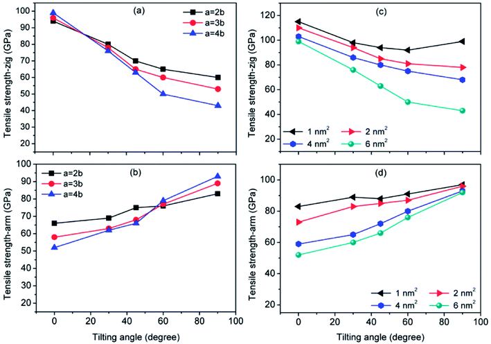
Fig. 6 shows the effect of tilting angle of rectangular nanohole (with different aspect ratios and areas) on the tensile strength of defective graphene sheets. No matter the variation of aspect ratio and area of rectangular nanohole, the tensile strength of zigzag defective graphene decreases, but the strength of armchair defective graphene increases with increasing tilting angle of rectangular nanohole.In Fig. 6(a) and (b), when the area of rectangular nanohole is maintained at 6 nm2, but the tilting angle is varied from 0° to 90°, the degree of weakening (strengthening) of tensile strength for zigzag (armchair) graphene sheet is dependent on the aspect ratio of the rectangular nanohole. For an aspect ratio of 2![[thin space (1/6-em)]](https://www.rsc.org/images/entities/char_2009.gif) :
:![[thin space (1/6-em)]](https://www.rsc.org/images/entities/char_2009.gif) 1, the tensile strength of zigzag (armchair) defective graphene slowly decreases (increases) with increasing tilting angle. But with an aspect ratio of 4
1, the tensile strength of zigzag (armchair) defective graphene slowly decreases (increases) with increasing tilting angle. But with an aspect ratio of 4![[thin space (1/6-em)]](https://www.rsc.org/images/entities/char_2009.gif) :
:![[thin space (1/6-em)]](https://www.rsc.org/images/entities/char_2009.gif) 1, with increasing tilting angle, the zigzag and armchair defective graphene undergo a process of significant weakening and strengthening, respectively.
1, with increasing tilting angle, the zigzag and armchair defective graphene undergo a process of significant weakening and strengthening, respectively.
From Fig. 6(c) and (d), for different areas of nanohole, there are dramatic changes in degree of tensile strength of defective graphene with increases in the tilting angle of the nanohole (with aspect ratio maintained at 4![[thin space (1/6-em)]](https://www.rsc.org/images/entities/char_2009.gif) :
:![[thin space (1/6-em)]](https://www.rsc.org/images/entities/char_2009.gif) 1). For example, when the area of nanohole in the graphene sheet is 1 nm2, the strengths of zigzag defective graphene with nanohole of tilting angles of 0°, 30°, 45°, 60° and 90° are 115 GPa, 98 GPa, 94 GPa, 92 GPa and 99 GPa, respectively (with tensile strength of zigzag pristine graphene sheet of 118 GPa). The strengths of armchair graphene with nanohole of tilting angles of 0°, 30°, 45°, 60° and 90° are 83 GPa, 89 GPa, 84 GPa, 87 GPa and 97 GPa, respectively (with tensile strength of armchair pristine graphene of 105 GPa). There is a minor change in the tensile strength with tilting angle increases (area of rectangular nanohole with 1 nm2), but when the area of nanohole is more than 1 nm2, such as at 2 nm2, 4 nm2 and 6 nm2, the tensile strength of zigzag (armchair) defective graphene is monotonically decreased (increased) along with the tilting angle of nanohole from 0° to 90°. During the tensile deformation of defective graphene with area of nanohole 2 nm2, the tensile strength of zigzag (armchair) defective graphene is gently decreased (increased) with increasing tilting angle. When the area of nanohole is up to 6 nm2, however, the zigzag (armchair) defective graphene undergoes a process of sharp weakening (strengthening). It can be summarized that variation in tilting angle of rectangular nanohole can cause decrease or increase in tensile strength of the graphene sheet. In addition, when the area and aspect ratio of the rectangular nanohole are large, the weakening or strengthening effects of rectangular nanohole on the tensile strength of defective graphene are considerably more.
1). For example, when the area of nanohole in the graphene sheet is 1 nm2, the strengths of zigzag defective graphene with nanohole of tilting angles of 0°, 30°, 45°, 60° and 90° are 115 GPa, 98 GPa, 94 GPa, 92 GPa and 99 GPa, respectively (with tensile strength of zigzag pristine graphene sheet of 118 GPa). The strengths of armchair graphene with nanohole of tilting angles of 0°, 30°, 45°, 60° and 90° are 83 GPa, 89 GPa, 84 GPa, 87 GPa and 97 GPa, respectively (with tensile strength of armchair pristine graphene of 105 GPa). There is a minor change in the tensile strength with tilting angle increases (area of rectangular nanohole with 1 nm2), but when the area of nanohole is more than 1 nm2, such as at 2 nm2, 4 nm2 and 6 nm2, the tensile strength of zigzag (armchair) defective graphene is monotonically decreased (increased) along with the tilting angle of nanohole from 0° to 90°. During the tensile deformation of defective graphene with area of nanohole 2 nm2, the tensile strength of zigzag (armchair) defective graphene is gently decreased (increased) with increasing tilting angle. When the area of nanohole is up to 6 nm2, however, the zigzag (armchair) defective graphene undergoes a process of sharp weakening (strengthening). It can be summarized that variation in tilting angle of rectangular nanohole can cause decrease or increase in tensile strength of the graphene sheet. In addition, when the area and aspect ratio of the rectangular nanohole are large, the weakening or strengthening effects of rectangular nanohole on the tensile strength of defective graphene are considerably more.
4. Discussions
In the tensile deformation process of pristine graphene, the stress on each carbon atom is gradually and uniformly increased with increasing tensile strain until fracture. When tensile deformation of graphene with rectangular nanohole is performed, however, the imperfect structure of defective graphene results in uneven distributions of stress on the carbon atoms. This is because the rectangular nanohole disrupts the perfect structure of the graphene, reducing the effective loading area of graphene during the tensile deformation. Therefore, the tensile strength of defective graphene sheet will be decreased, and as the area of rectangular nanohole increases, the tensile strength of defective graphene becomes smaller and smaller.Similar results were obtained from quantized fracture mechanics (QFM), an energy-based theory based on discrete crack growth, proposed by substituting the differentials in Griffith's energy balance equation with finite differences.23,31,43,44 QFM can be applied to study the tensile strength of defective graphene with defects of any size and shape. Under the I loading, a blunt nanocrack (length is 2L) on finite-width graphene (width is 2ω) is considered in this study. The tensile strength of graphene with nanohole σf using QFM is given by31,43,44
 | (2) |
 is the tip radius of the nanocrack in the graphene, and
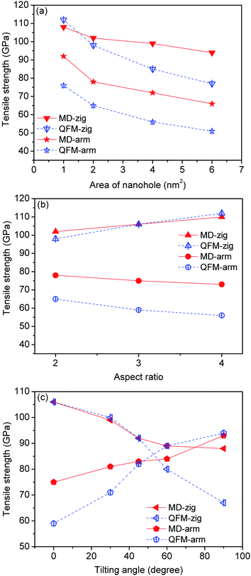
  is the fracture quantum, which is defined as the minimum nanocrack extension corresponding to the breaking of one interatomic bond perpendicular to the tensile direction (r0 = 1.42 Å is the carbon–carbon bond length in graphene sheet).31 In prediction of tensile strength of defective graphene with rectangular nanohole using QFM, it must be pointed out that the nanocrack length 2L of formula (2) corresponds to the length of the void perpendicular to the tensile direction in defective graphene sheet. Fig. 7 shows a comparison of tensile strength of defective graphene between the molecular dynamics simulations (MD) and quantized fracture mechanics (QFM). From Fig. 7(a), the tensile strength of graphene (both zigzag and armchair direction) from MD and QFM both decreased with increasing area of rectangular nanohole. The strength of defective graphene from MD is larger than that from QFM, perhaps because the shape of nanohole in the present simulations is a rectangle, but not a perfectly sharp rectangular nanohole.
From Fig. 7(b), increasing aspect ratio of rectangular nanohole (from 2![[thin space (1/6-em)]](https://www.rsc.org/images/entities/char_2009.gif) :
:![[thin space (1/6-em)]](https://www.rsc.org/images/entities/char_2009.gif) 1 to 4
1 to 4![[thin space (1/6-em)]](https://www.rsc.org/images/entities/char_2009.gif) :
:![[thin space (1/6-em)]](https://www.rsc.org/images/entities/char_2009.gif) 1) can strengthen (weaken) the defective zigzag (armchair) graphene both from MD simulations and QFM predictions. When the tilting angle of the rectangular nanohole is increased from 0° to 90°, the variations in defective graphene from the MD calculations correspond well with the tendency from QFM theoretical prediction, as shown in Fig. 7(c). This change in tensile strength of defective graphene occurs mainly because the rectangular nanohole of effective length perpendicular to the tensile direction changes with increasing aspect ratio and tilting angle of rectangular nanohole (Fig. 8). And the effective loading area of the defective graphene sheet will also change. For example, when the area and tilting angle are kept constant but the aspect ratio of the rectangular nanohole is increased from 2
1) can strengthen (weaken) the defective zigzag (armchair) graphene both from MD simulations and QFM predictions. When the tilting angle of the rectangular nanohole is increased from 0° to 90°, the variations in defective graphene from the MD calculations correspond well with the tendency from QFM theoretical prediction, as shown in Fig. 7(c). This change in tensile strength of defective graphene occurs mainly because the rectangular nanohole of effective length perpendicular to the tensile direction changes with increasing aspect ratio and tilting angle of rectangular nanohole (Fig. 8). And the effective loading area of the defective graphene sheet will also change. For example, when the area and tilting angle are kept constant but the aspect ratio of the rectangular nanohole is increased from 2![[thin space (1/6-em)]](https://www.rsc.org/images/entities/char_2009.gif) :
:![[thin space (1/6-em)]](https://www.rsc.org/images/entities/char_2009.gif) 1 to 4
1 to 4![[thin space (1/6-em)]](https://www.rsc.org/images/entities/char_2009.gif) :
:![[thin space (1/6-em)]](https://www.rsc.org/images/entities/char_2009.gif) 1, the effective length of the rectangular nanohole of zigzag (armchair) graphene sheet becomes small (large), but the effective loading area of zigzag (armchair) graphene sheet becomes large (small). When the area and aspect ratio are kept constant but the tilting angle of the rectangular nanohole is increased from 0° to 90°, the effective loading areas of zigzag and armchair graphene sheet become small and large, respectively. This variation of effective loading area of defective graphene ultimately results in the regular change of tensile strength of defective graphene sheet.
1, the effective length of the rectangular nanohole of zigzag (armchair) graphene sheet becomes small (large), but the effective loading area of zigzag (armchair) graphene sheet becomes large (small). When the area and aspect ratio are kept constant but the tilting angle of the rectangular nanohole is increased from 0° to 90°, the effective loading areas of zigzag and armchair graphene sheet become small and large, respectively. This variation of effective loading area of defective graphene ultimately results in the regular change of tensile strength of defective graphene sheet.
5. Conclusions
In this study, the effects of areas, aspect ratios and orientations of rectangular nanohole were studied on the tensile strength of graphene sheet using molecular dynamics simulations based on the adaptive intermolecular reactive empirical bond order (AIREBO) potential. It was found that the tensile strength of defective graphene sheet significantly relied on the area, aspect ratio and orientation of rectangular nanohole. With increasing area of rectangular nanohole, both the tensile strength of zigzag and armchair graphene sheet monotonically decrease. In addition, the aspect ratio and orientation of rectangular nanohole also have influence on the tensile strength of defective graphene. When the long axis (“a” axis) of rectangular nanohole is parallel to the tensile direction, the tensile strength of defective graphene increases with the aspect ratio increase. But for the condition of the long axis of nanohole perpendicular to the tensile direction, the tensile strength of graphene decreases with the aspect ratio increase. Moreover, when the tilting angle of rectangular nanohole ranges from 0° to 90°, the tensile strength of defective zigzag graphene gradually drops, but the tensile strength of defective armchair graphene increases. Furthermore, it was found that the tensile strength of defective graphene is more sensitive to the tilting angle of nanohole at larger area and aspect ratio than at smaller area and aspect ratio. Comparing the effects of area, aspect ratio and orientation on the tensile strength of defective graphene, it can be concluded that the tensile strength of graphene with rectangular nanohole mainly depends on the rectangular nanohole of size perpendicular to the tensile direction, named for the effective nanocrack length. For instance, when the area of nanohole is kept constant, the tensile strength of defective graphene decreases with increase in effective nanocrack length. The variation of tensile strength of MD simulations is in good agreement with that predicted by the energy-based quantized fracture mechanics (QFM). The present results suggest that the effect of rectangular nanohole on the tensile strength of graphene provides essential information for predictive optimization of mechanical properties and controllable structural modification of graphene through topological defect engineering. And the findings will also provide a useful guideline for designing mechanically robust graphene-enhanced nanocomposites and graphene-based devices, such as nanosensors, DNA-sequencing tools and selective molecular sieving devices.Conflicts of interest
There are no conflicts to declare.Acknowledgements
This work is supported by the Natural Science Foundation of Guizhou Province of China (Grant No. [2015]2001), the innovation team of Anshun University (Grant No. 2015PT02), and the school project of Anshun University (Grant No. [2015]AQ07).References
- A. K. Geim and K. S. Novoselov, The rise of graphene, Nat. Mater., 2007, 6(3), 183–191 CrossRef CAS PubMed.
- K. S. Novoselov, Z. Jiang, Y. Zhang, S. V. Morozov, H. L. Stormer, U. Zeitler, J. C. Maan, G. S. Boebinger, P. Kim and A. K. Geim, Room-temperature quantum hall effect in graphene, Science, 2007, 315(5817), 1379 CrossRef CAS PubMed.
- C. Lee, X. Wei and J. W. Kysar, et al., Measurement of the Elastic Properties and Intrinsic Strength of Monolayer Graphene, Science, 2008, 321, 385–388 CrossRef CAS PubMed.
- F. Liu, P. Ming and J. Li, Ab initio calculation of ideal strength and phonon instability of graphene under tension, Phys. Rev. B: Condens. Matter Mater. Phys., 2007, 76, 064120 CrossRef.
- H. Zhao, K. Min and N. R. Aluru, Size and chirality dependent elastic properties of graphene nanoribbons under uniaxial tension, Nano Lett., 2009, 9(8), 3012–3015 CrossRef CAS PubMed.
- Y. Teng Liang, B. K. Vijayan and K. A. Gray, et al., Minimizing graphene defects enhances Titania nanocomposite-based photocatalytic reduction of CO2 for improved solar fuel production, Nano Lett., 2011, 11(7), 2865–2870 CrossRef PubMed.
- Y.-H. Zhang, Ya-B. Chen and K.-G. Zhou, et al., Improving gas sensing properties of graphene by introducing dopants and defects: a first-principles study, Nanotechnology, 2009, 20, 185504 CrossRef PubMed.
- C. Liu, Z. Yu and D. Neff, et al., Graphene-based supercapacitor with an ultrahigh energy density, Nano Lett., 2010, 10(12), 4863–4868 CrossRef CAS PubMed.
- Z.-S. Wu, W. Ren and L. Xu, et al., Doped graphene sheets as anode materials with superhigh rate and large capacity for lithium ion batteries, ACS Nano, 2011, 5(7), 5463–5471 CrossRef CAS PubMed.
- S. J. Heerema and C. Dekker, Graphene nanodevices for DNA sequencing, Nat. Nanotechnol., 2016, 11, 127–136 CrossRef CAS PubMed.
- S. P. Koenig, L. Wang and J. Pellegrino, et al., Selective molecular sieving through porous graphene, Nat. Nanotechnol., 2012, 7, 728–732 CrossRef CAS PubMed.
- R. Khare, S. L. Mielke and J. T. Paci, et al., Coupled quantum mechanical/molecular mechanical modeling of the fracture of defective carbon nanotubes and graphene sheets, Phys. Rev. B, 2007, 75, 075412 CrossRef.
- A. Zandiatashbar, G.-H. Lee and S. Joo An, et al., Effect of defects on the intrinsic strength and stiffness of graphene, Nat. Commun., 2014, 5, 3186 Search PubMed.
- F. Banhart, J. Kotakoski and A. V. Krasheninnikov, Structural defects in graphene, ACS Nano, 2011, 5(1), 26–41 CrossRef CAS PubMed.
- W. Yan, Q. Xie and X. Qin, et al., First-principle analysis of photolelectronic properties of silicon-carbon materials with graphene-like honeycomb structure, Comput. Mater. Sci., 2017, 126, 336–343 CrossRef CAS.
- N. Jing, Q. Xue and C. Ling, et al., Effect of defects on Young's modulus of graphene sheet: a molecular dynamics simulation, RSC Adv., 2012, 2, 9124–9129 RSC.
- H. Tongwei, H. Pengfei and W. Jian, et al., Effect of Vacancy Defects on Tensile Mechanical Properties of Single Graphene Sheets, Journal of Tongji University (Natural Science), 2010, 38(8), 1210–1214 Search PubMed.
- Z. Xiaoxi, L. Junhua and L. Xuyang, et al., Influence of silicon doping on mechanical properties of graphene sheets under tension, Journal of University of Science and Technology of China, 2014, 44(3), 238–243 Search PubMed.
- B. Mortazavi, S. Ahzi and V. Toniazzo, et al., Nitrogen doping and vacancy effects on the mechanical properties of graphene: A molecular dynamics simulation, Phys. Lett. A, 2012, 376, 1146–1153 CrossRef CAS.
- Q. X. Pei, Y. W. Zhang and V. B. Shenoy, A molecular dynamics study of the mechanical properties of hydrogen functional graphene, Carbon, 2010, 48, 898–904 CrossRef CAS.
- Q.-X. Pei, Y.-W. Zhang and V. B. Shenoy, Mechanical properties of methyl functionalized graphene: a molecular dynamics simulation, Nanotechnology, 2010, 21, 115709 CrossRef PubMed.
- T. Han, Y. Shi and P. He, et al., The effect of Stone-Wales topological defects on the tensile mechanical properties of single graphene sheets, Chin. J. Solid Mech., 2011, 32(6), 619–624 CAS.
- M. C. Wang, C. Yan and L. Ma, et al., Effect of defects on fracture strength of graphene sheets, Comput. Mater. Sci., 2012, 54, 236–239 CrossRef CAS.
- L. He, S. Guo and J. Lei, et al., The effect of Stone-Thrower-Wales defects on mechanical properties of graphene sheets – A molecular dynamics study, Carbon, 2014, 75, 124–132 CrossRef CAS.
- Y. Wei, J. Wu and H. Yin, et al., The nature of strength enhancement and weakening by pentagon-heptagon defect in graphene, Nat. Mater., 2012, 11, 759–763 CrossRef CAS PubMed.
- J. Han, S. Ryu and D. Sohn, et al., Mechanical strength characteristics of asymmetric tilt grain boundaries in graphene, Carbon, 2014, 68, 250–257 CrossRef CAS.
- F. Meng, C. Chen and J. Song, et al., Dislocation shielding of a nanocrack in graphene: Atomistic simulation and Continuum modeling, J. Phys. Chem. Lett., 2015, 6(20), 4038–4042 CrossRef CAS PubMed.
- Y. Liu and X. Chen, Mechanical properties of nanoporous graphene membrane, J. Appl. Phys., 2014, 115, 034303 CrossRef.
- D. Cohen-tanugi and J. C. Grossman, Mechanical strength of nanoporous graphene as a desalination membrane, Nano Lett., 2014, 14(11), 6171–6178 CrossRef CAS PubMed.
- B. Zhang, L. Mei and H. Xiao, Nanofracture in graphene under complex mechanical stresses, Appl. Phys. Lett., 2012, 101, 121915 Search PubMed.
- H. Zhao and N. R. Aluru, Temperature and strain-rate dependent fracture strength of graphene, J. Appl. Phys., 2010, 108, 064321 CrossRef.
- M.-Q. Le and R. C. Batra, Single-edge crack growth in graphene sheets under tension, Comput. Mater. Sci., 2013, 69, 381–388 CrossRef CAS.
- M.-Q. Le and R. C. Batra, Crack propagation in pre-strained single layer graphene sheets, Comput. Mater. Sci., 2014, 84, 238–243 CrossRef CAS.
- M.-Q. Le and R. C. Batra, Mode-I stress intensity factor in single layer graphene sheets, Comput. Mater. Sci., 2016, 118, 251–258 CrossRef CAS.
- M.-Q. Le, Y. Umeno, Fracture of monolayer boronitrene and its interface with graphene, Int. J. Fract., 2017, 205(2):151–168 Search PubMed.
- S. J. Stuart, A. B. Tutein and J. A. Harrison, A Reactive Potential for Hydrocarbons with Intermolecular Interactions, J. Chem. Phys., 2000, 112, 6472–6486 CrossRef CAS.
- B. Ni, S. B. Sinnott and P. T. Mikulski, et al., Compression of carbon nanotubes filled with C60, CH4, or Ne: predictions from molecular dynamics simulations, Phys. Rev. Lett., 2002, 88, 205505 CrossRef PubMed.
- G. J. Martyna, D. J. Tobias and M. L. Klein, Constant pressure molecular dynamics algorithms, J. Chem. Phys., 1994, 101, 4177–4189 CrossRef CAS.
- M. Parrinello and A. Rahman, Polymorphic transitions in single crystals : A new molecular dynamics method, J. Appl. Phys., 1981, 52(12), 7182–7190 CrossRef CAS.
- M. E. Tuckerman, J. Alejandre and R. López-Rendón, et al., A Liouville-operator derived measure-preserving integrator for molecular dynamics simulations in the isothermal–isobaric ensemble, J. Phys. A: Math. Gen., 2006, 39, 5629–5651 CrossRef CAS.
- W. Shinoda, M. Shiga and M. Mikami, Rapid estimation of elastic constants by molecular dynamics simulation under constant stress, Phys. Rev. B, 2004, 69, 134103 CrossRef.
- A. Stukowski, Visualization and analysis of atomistic simulation data with OVITO – the open Visualization Tool, Modell. Simul. Mater. Sci. Eng., 2010, 18, 015012 CrossRef.
- N. Pugno, A. Carpinteri and M. Ippolito, et al., Atomistic fracture : QFM vs. MD, Eng. Fract. Mech., 2008, 75, 1794–1803 CrossRef.
- N. M. Pugno and R. S. Ruoff, Quantized fracture mechanics, Philos. Mag., 2004, 84(27), 2829–2845 CrossRef CAS.
| This journal is © The Royal Society of Chemistry 2018 |

