DOI:
10.1039/C8RA02396D
(Paper)
RSC Adv., 2018,
8, 17938-17943
Oxidative desulfurization of dibenzothiophene catalyzed by α-MnO2 nanosheets on palygorskite using hydrogen peroxide as oxidant
Received
19th March 2018
, Accepted 30th April 2018
First published on 16th May 2018
Abstract
Palygorskite (Pal)-supported α-MnO2 nanosheets (Ns-MnPal) combine the adsorption features of Pal with the catalytic properties of α-MnO2 nanosheets. They were prepared and examined in the catalytic oxidative desulfurization (ODS) of dibenzothiophene (DBT) from a model oil employing 30 wt% H2O2 as the oxidant under mild conditions. The supported catalyst was fabricated by the solvothermal method, and effective immobilization of α-MnO2 nanosheets was confirmed by X-ray diffraction (XRD), scanning electron microscopy (SEM), energy dispersive spectroscopy (EDS), thermogravimetric analysis (TGA), X-ray photoelectron spectroscopy (XPS) and N2 adsorption. The influence of various solvents, solvent volume, reaction temperature, reaction time, catalyst amount and H2O2/sulfur molar ratio on ODS was investigated. Using 20 mL of acetonitrile as a solvent, maximum sulfur removal of 97.7% was achieved for ODS of DBT in 1.5 h using a Ns-MnPal/oil ratio of 0.2 g L−1, reaction temperature of 50 °C and H2O2/sulfur molar ratio of 4. As solid catalysts, supported α-MnO2 nanosheets could be separated from the reaction readily. The catalyst was recycled seven times and showed no significant loss in activity.
Introduction
The sulfur content in transportation fuels is a very serious environmental concern because the sulfur compounds in fuel are converted to toxic SOx during their combustion.1 SOx contribute to acid rain and poison the catalysts for nitrogen oxide (NOx) reduction.2,3 Therefore, the concentration of sulfur in fuels is limited severely and its regulation level is becoming lower and lower from year to year. Hydrodesulfurization (HDS) is the conventional process for reducing organosulfur compounds in gasoline, diesel and other intermediate distillates. This process is highly efficient for removing thiols, sulfides, disulfides, and some thiophene derivatives, but less effective for dibenzothiophene (DBT) derivatives with steric hindrance on the sulfur atom. Possible ways of increasing the effectiveness of HDS for producing low-sulfur products include use of higher temperatures and pressures, more active catalysts or longer residence times. However, these alternatives are costly to refineries.4 Therefore, several alternative approaches have been used, such as biodesulfurization,5 selective adsorption,6 extraction by ionic liquids7 and catalytic oxidative desulfurization (ODS).8–12
Catalytic ODS, as an alternative to the conventional HDS, has been considered a promising method for deep desulfurization technology because it can be carried out under mild conditions, such as relatively low temperature, pressure and cost of operation when compared with HDS, and can meet future environmental regulations for low-sulfur diesel.13–17 In general, catalytic ODS proceeds in two steps: oxidation of sulfur is followed by solvent extraction or solid adsorption. In catalytic ODS, the sulfur compounds in diesel are oxidized to form highly polarized sulfoxides and sulfones. These sulfoxides and sulfones are substantially more polar than the respective sulfides, so a solvent-extraction step can be a convenient way to remove selectively the oxidized sulfur compounds from the oil phase.18 Usually, hydrogen peroxide is considered a powerful oxidant of sulfur compounds, and the best result will be achieved using H2O2 in conjunction with heterogeneous catalysts. Various studies on this process have been reported, such as H2O2/Mo/gama-Al2O3,19 H2O2/heteropolyanion,20 H2O2/peroxotungstate/MCM-41 (ref. 21) and H2O2/[Bmim]FeCl4/TiO2.22
As mentioned above, supported catalysts have been used in investigations to enhance the efficiency of the oxidant in the ODS process. Palygorskite (Pal) is a crystalline hydrated magnesium aluminum silicate mineral with a unique three-dimensional structure,23 but its use to oxidize sulfur-containing compounds in diesel has rarely been reported. Therefore, the main objectives of the present study were to report: (i) preparation of Pal-supported α-MnO2 nanosheets (Ns-MnPal) in a solvothermal method; (ii) characterization of samples by X-ray diffraction (XRD), scanning electron microscopy (SEM), energy dispersive spectroscopy (EDS), thermogravimetric analysis (TGA), X-ray photoelectron spectroscopy (XPS) and N2 adsorption; (iii) the effective use of Ns-MnPal in ODS of DBT from a model oil employing 30 wt% H2O2 as the oxidant reagent under mild conditions.
Experimental
Materials
Pal was supplied by Jiangsu Xuyi Anhalt Non-metallic Mining. DBT, n-octane, potassium permanganate, hydrochloric acid, acetonitrile, methanol, dimethylformamide (DMF) and hydrogen peroxide were obtained from Sigma-Aldrich.
Catalyst preparation
In a typical procedure, 0.31 g of KMnO4 and 0.23 mL of HCl (37 wt%) were dissolved in 65 mL of deionized water under magnetic stirring to form the precursor solution, followed by the addition of 0.5 g of Pal to form a brown solution. After stirring for ≈20 min, the mixture was transferred to a Teflon™-lined stainless-steel autoclave with a capacity of 100 mL. The autoclave was then heated in an electric oven at 150 °C for 8 h. After the autoclave had cooled down naturally to room temperature, the product was harvested by centrifugation, washed with distilled deionized water, and dried in air at ambient temperature.
Characterization
The XRD patterns of the catalysts were observed using a Rigaku ULTIMA IV diffractometer with high-intensity Cu/Kα radiation at 2θ angles of 5–90°. TGA curves were determined using a Netzsch TG209F3 thermogravimetric analyzer at a heating rate of 10 °C min−1 under a nitrogen atmosphere. Surface morphology of the catalyst was investigated using a JEOL JEM-2100 scanning electron microscope. EDS was done for elemental analysis. The chemical state of the formed oxides was determined by XPS using a Thermo Scientific ESCALAB 250Xi spectrometer with Mg Kα radiation (1253.6 eV) as the X-ray source. The Brunauer–Emmett–Teller (BET) method was utilized to measure the specific surface area and pore volume of the catalysts by accelerated surface area and porosity using a Micromeritics ASAP 2010 system. The pore-size distribution was assessed by the adsorption branch of the isotherm using the Barrett–Joyner–Halenda (BJH) method.
ODS procedure
Oxidation of model sulfur compounds was done in batch mode. In a typical experiment, the required amounts of solvent, Ns-MnPal, 30 wt% H2O2, and model oil (DBT was dissolved in n-octane, with a sulfur concentration of 500 μg mL−1) were added to a flask in turn and stirred vigorously in an oil bath at the reaction temperature. After the reaction, the catalyst was centrifuged and the upper layer of the reaction samples withdrawn and subjected to gas chromatography-pulsed flame-photometric detection.24
Results and discussion
XRD of samples
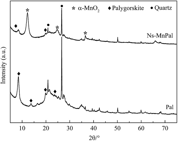
XRD was used to characterize the phase and crystal structure of the samples. Fig. 1 reveals the crystal structure of Pal and Ns-MnPal. For Pal, the reflections positioned at 2θ values of 8.3°, 13.9°, 19.5° and 24.5° corresponded to crystalline Pal and 2θ values at 20.5° and 26.5° were assigned to crystalline quartz.25 For Ns-MnPal, the reflection intensity of Pal at 2θ = 8.3° was reduced. Apart from the Pal reflections, the diffraction peaks at 2θ values of 12.2°, 24.7°, 36.6° could be identified as the (110), (220) and (400) phases of tetragonal crystalline α-MnO2 (JCPDS 44-0141), indicating that α-MnO2 was immobilized on Pal fibers.26,27
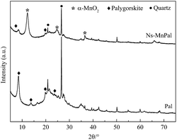 |
| | Fig. 1 XRD patterns of Pal and Ns-MnPal. | |
TGA
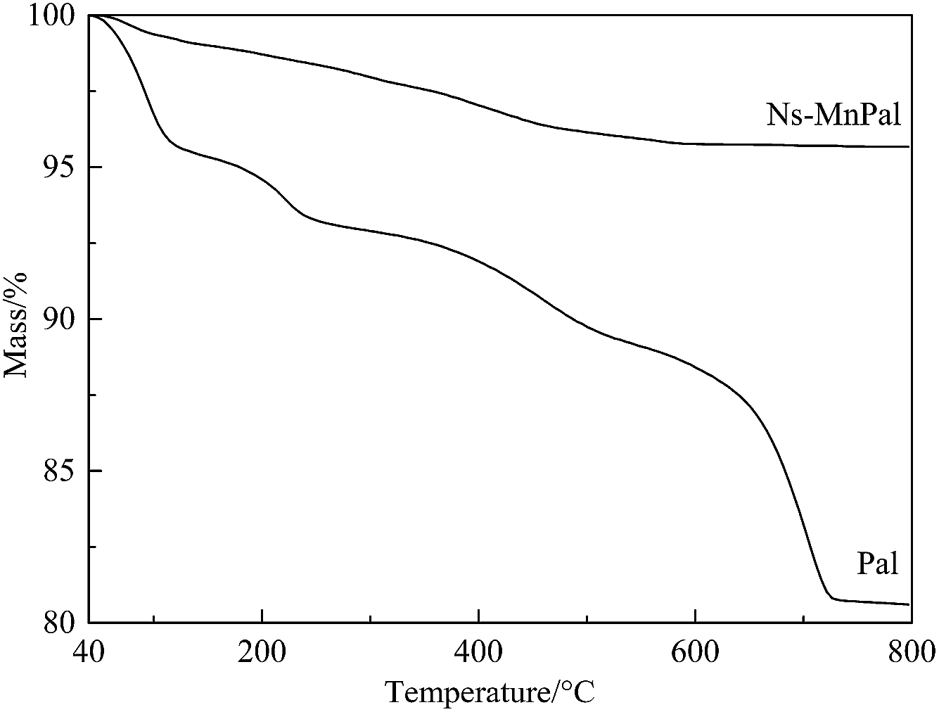
Fig. 2 shows the TGA curves of Pal and Ns-MnPal. Four mass-loss steps were observed in the TGA curve of Pal. The mass loss of APT below 130 °C was due to removal of the physically adsorbed water and the first part of zeolitic water.28 The mass loss between 120 and 250 °C was due to the release of residual zeolitic water and partially coordinated water.29 The mass loss between 280 and 550 °C was ascribed to the release of the residual coordinated water and structural water. The mass loss above 550 °C was due to the partial dehydroxylation of Mg–OH groups.30,31 However, almost no mass loss was observed in the TGA curve of Ns-MnPal, which suggested that the silica component had combined with α-MnO2 to form a hybrid structure with superior thermal stability.
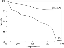 |
| | Fig. 2 TGA of Pal and Ns-MnPal. | |
Surface morphology of samples
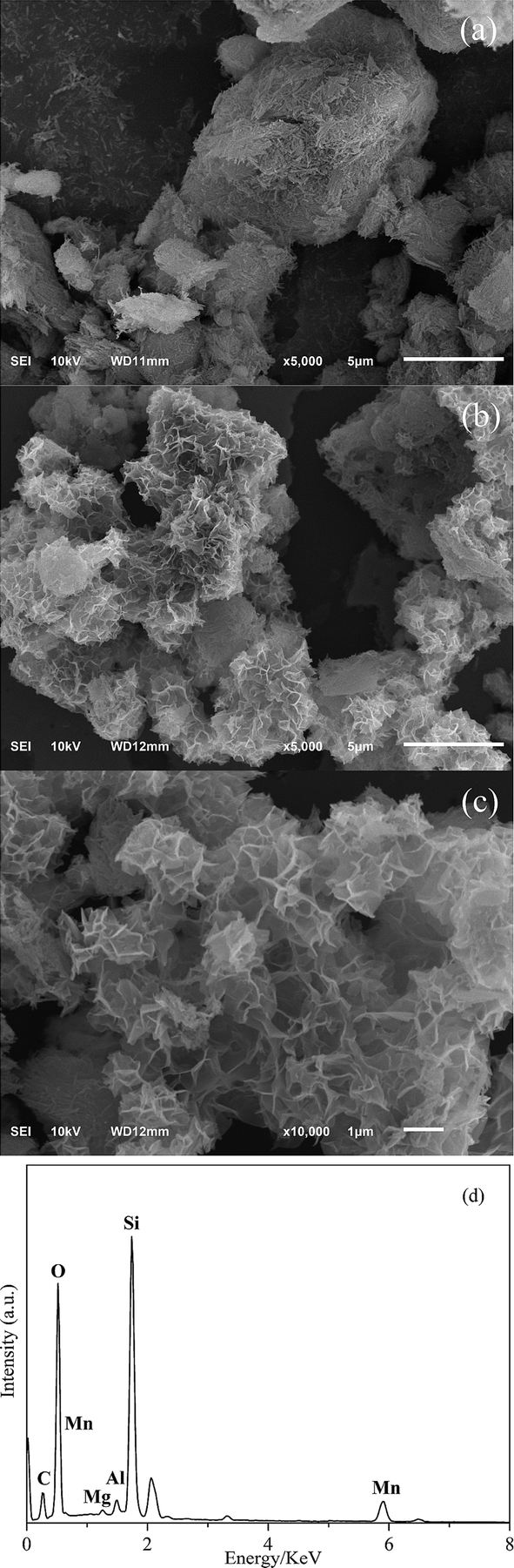
Fig. 3 shows the SEM and EDS observations of Pal and Ns-MnPal composites. Fig. 3a shows that Pal exhibited a fibrous structure and some fibers formed straight parallel aggregates. Fig. 3b and c are obviously different to that of Pal. Ns-MnPal composites showed a tighter and rougher surface, which could be attributed to the introduction of nanosized α-MnO2 sheets on the Pal surface. The corresponding EDS spectra of the Ns-MnPal composite are displayed in Fig. 3d, which reveals that Mn was detected in the composite.32 According to the XRD results, it could be deduced that α-MnO2 was deposited on the walls of Pal.
 |
| | Fig. 3 SEM images of (a) Pal; (b & c) Ns-MnPal; and (d) EDS spectra of Ns-MnPal. | |
Surface chemical composition of samples
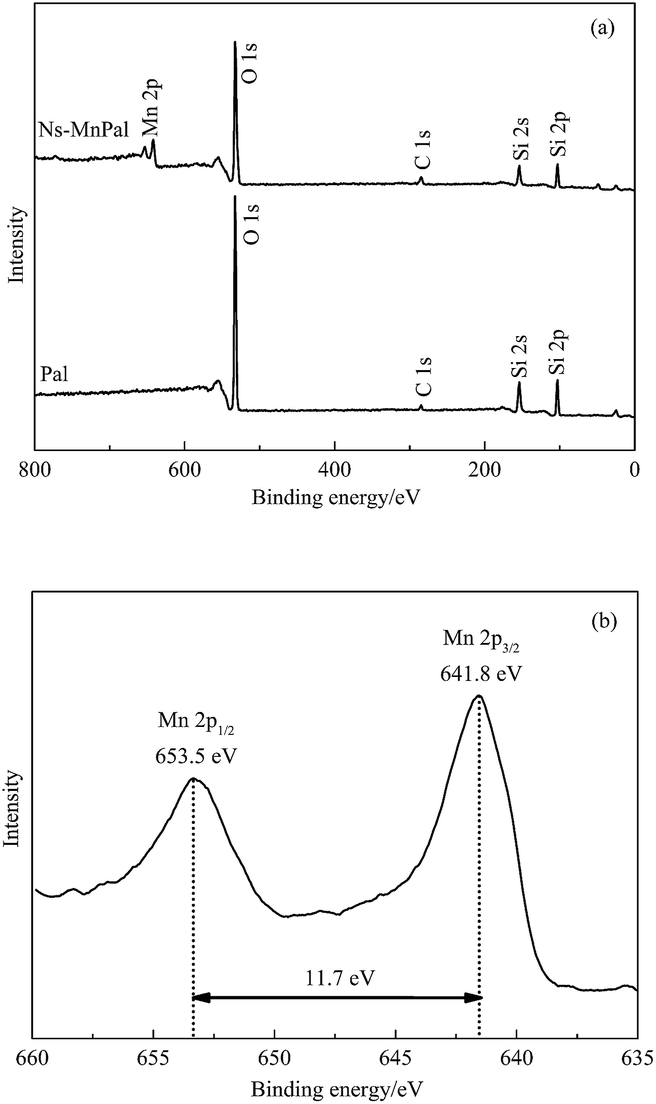
Elemental compositions of Ns-MnPal samples were verified further using XPS. Fig. 4 shows the typical XPS spectra of Pa and Ns-MnPal composites. According to the survey spectrum shown in Fig. 4a, Si, O, and C were found in Pal, of which the element C was on the surface as the internal reference. However, an additional Mn signal was observed in the XPS spectrum of Ns-MnPal composites, illustrating the attachment of MnO2 on the surface of Pal. Fig. 4b shows the high-resolution Mn2p spectrum of MnPal composites, in which the binding energy peaks of Mn2p3/2 and Mn2p1/2 were at 641.7 eV and 653.4 eV, respectively. The Ns-MnPal composite showed a consistent spin-energy separation of 11.7 eV between the Mn2p1/2 peak and Mn2p3/2 peak. These results are in good accordance with the reported data of MnO2, and suggest a tetravalent oxidation state for Mn.33,34
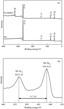 |
| | Fig. 4 XPS spectra of samples. (a) Survey spectrum of Pal and Ns-MnPal; (b) Mn2p. | |
N2 adsorption–desorption isotherms
The nitrogen adsorption–desorption isotherms of Pal and Ns-MnPal samples are shown in Fig. 5. Both samples had typical IV isotherm curves containing a hysteresis between adsorption and desorption at a relative pressure (P/P0) ranging from 0.4 to 0.9, suggesting that a mesopore was present in Pal and Ns-MnPal.35 The BET surface area, pore volume, and average pore size of Pal and Ns-MnPal are summarized in Table 1. Pal had a BET surface area of 249.6 m2 g−1 whereas, after composite formation with α-MnO2, the BET surface area fell to 174.9 m2 g−1. The pore volume of Pal and Ns-MnPal composite were 1.7 m3 g−1 and 1.5 m3 g−1, respectively. The main pore size distribution centers were at 10.58 nm for Pal and 5.42 nm for Ns-MnPal. The decrease in the specific surface area, pore volume, and average pore size was due mainly to the pore-filling of α-MnO2 nanoparticles.
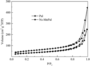 |
| | Fig. 5 N2 adsorption–desorption isotherms of Pal and Ns-MnPal. | |
Table 1 Physical properties of Pal and Ns-MnPal
| Sample |
BET surface area m2 g−1 |
Total pore volume m3 g−1 |
Average pore size nm |
| Pal |
180.98 |
0.67 |
17.05 |
| Ns-MnPal |
112.99 |
0.38 |
13.20 |
Reaction conditions on sulfur removal
Three types of extraction solvents were used to evaluate the effect of solvent on the sulfur elimination by the ODS process: methanol, acetonitrile and dimethylformamide (DMF). As seen from Fig. 6, the sulfur removal over Ns-MnPal catalyst decreases in the following order: DMF > acetonitrile > methanol. Although DMF shows the best sulfur removal among the three types of extraction solvents, DMF was easily miscible with the oil phase, resulting in low recovery of the oil phase after extraction. Acetonitrile has lower solubility with the oil phase and lower boiling point and can be easily separated with sulfoxides or/and sulfones after oxidation-extraction by the method of distillation.22 Therefore, acetonitrile was chosen as the best extraction solvent in this paper.
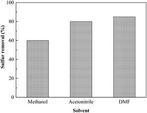 |
| | Fig. 6 Effect of extraction solvents on sulfur removal. Conditions: Ns-MnPal/oil ratio = 0.2 g L−1, H2O2/sulfur = 5![[thin space (1/6-em)]](https://www.rsc.org/images/entities/char_2009.gif) :1 (molar ratio), T = 50 °C, t = 1.5 h, and solvent/oil = 1:1 (volume ratio). :1 (molar ratio), T = 50 °C, t = 1.5 h, and solvent/oil = 1:1 (volume ratio). | |
We wished to investigate the effect of the volume of acetonitrile on sulfur removal. Hence, sulfur removal with various acetonitrile/oil volume ratios was carried out at 50 °C. As shown in Fig. 7, sulfur removal was promoted greatly with an increase in the acetonitrile/oil volume ratio. Sulfur removal was only 7.3% after oxidation for 1.5 h when acetonitrile is not used for extraction. However, when the acetonitrile/oil volume ratio was increased from 1:2 to 2:1, sulfur removal increased from 42.1 to 95.8% in 1.5 h. With a further increase in this ratio, an obvious increase in sulfur removal was not observed. Therefore, 2:1 was chosen as the best acetonitrile/oil volume ratio.
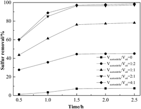 |
| | Fig. 7 Effect of acetonitrile/oil volume ratios on sulfur removal. Conditions: Ns-MnPal/oil ratio = 0.2 g L−1, H2O2/sulfur = 5:1 (molar ratio), and T = 50 °C. | |
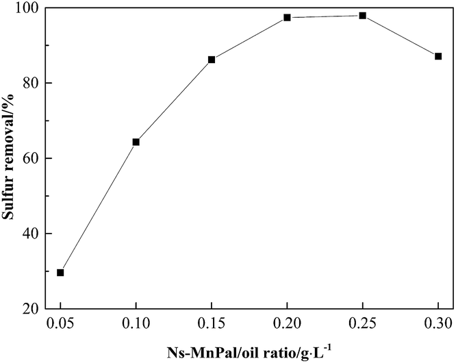
Fig. 8 shows the effect of the Ns-MnPal/oil ratio on sulfur removal. Sulfur removal increased significantly with an increasing Ns-MnPal/oil ratio from 0.05 g L−1 to 0.15 g L−1, gently from 0.15 g L−1 to 0.2 g L−1, and then levelled off at >0.25 g L−1. These results suggested that the catalyst was necessary for this oxidation and played an important part in the reaction. However, sulfur removal decreased slightly when 0.3 g L−1 of Ns-MnPal was used. This may have occurred because the catalyst could increase the decomposition of H2O2, resulting in reduced efficiency of the oxidant. Therefore, 0.2 g L−1 of Ns-MnPal/oil was chosen as the most suitable amount in subsequent investigations.
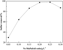 |
| | Fig. 8 Effect of catalyst amount on sulfur removal. Conditions: H2O2/sulfur = 5:1 (molar ratio), T = 50 °C, t = 1.5 h, and acetonitrile/oil = 1:1 (volume ratio). | |
A series of ODS procedures were carried out to investigate the effect of temperature on sulfur removal. As shown in Fig. 9, sulfur removal increased with increasing temperature and, within the temperature increase from 30 to 50 °C, the desulfurization efficiency was advanced visibly after reaction for 1.5 h. When the temperature was 50 °C, sulfur removal could reach 97.7% in 1.5 h and DBT could be removed almost completely for 2 h whereas, at 30 °C, sulfur removal appeared to be unsatisfactory. This phenomenon may have been because the oxidant and catalyst could not work efficiently at a lower reaction temperature. However, sulfur removal declined instead when the reaction temperature exceeded 50 °C. This phenomenon may have related to the loss of oxidant by the thermal decomposition of H2O2 to H2O and O2.36–38
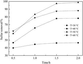 |
| | Fig. 9 Effect of different reaction temperatures on the reaction. Conditions: Ns-MnPal/oil ratio = 0.2 g L−1, H2O2/sulfur = 5:1 (molar ratio), T = 50 °C, and acetonitrile/oil = 2:1 (volume ratio). | |
To study the effect of the amount of oxidizing agent on oxidative properties, reactions under different H2O2/sulfur molar ratios were carried out at 60 °C. Stoichiometry dictates that 2 mol of H2O2 is sufficient to complete the conversion of DBT to DBTO2 but, in practice, more H2O2 is necessary for this reaction.8,39 As shown in Fig. 10, sulfur removal was only 67.1% when the H2O2/sulfur molar ratio was 2:1 within 1.5 h due to the self-decomposition of H2O2. Upon further increase in the H2O2/sulfur molar ratio to 4:1 enabled DBT to be removed completely in 1.5 h.
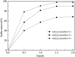 |
| | Fig. 10 Effect of H2O2/sulfur (molar ratio) on sulfur removal. Conditions: Ns-MnPal/oil ratio = 0.2 g L−1, T = 50 °C, and acetonitrile/oil = 2:1 (volume ratio). | |
According to the literature and our results, a plausible mechanism could be proposed. The hydroperoxy manganate group could be formed by nucleophilic attack of H2O2 on the bridging oxo ligands of the manganese dioxide species on the Pal surface. Subsequently, the hydroperoxy manganate species undergoes reversible loss of a water molecule to produce monoperoxo species. As a result, the peroxo group is activated in an electrophilic manner via coordination to the high-valence manganese atom. In the same way, it is possible to form diperoxo species. Oxidation can proceed by nucleophilic attack of the sulfur atom in DBT on a peroxo group of the mono- or diperoxo species to form sulfoxide and a regenerated polymanganate or monoperoxo species, respectively.
Reusability of catalyst
Separation and recycling of catalysts are essential steps in catalytic technology with regard to economic feasibility. Thus, the reusability of the catalyst was also investigated. After each catalytic ODS cycle, the used catalyst was filtered from the model oil, washed four times with methanol and dried in air at 100 °C for use in the subsequent run. Sulfur removal decreased slightly from 97.7 to 94.2% after three recycles and then dropped to 89.8% after seven reaction cycles (Fig. 11). As shown in Fig. 12, the active crystals of the catalyst used seven times reduced slightly. This was probably due to the loss of active components during the reaction and separation. The catalyst had notable repeated-use performance.
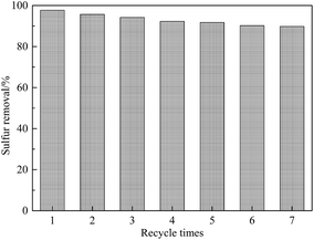 |
| | Fig. 11 Influence of recycle times on sulfur removal. Conditions: Ns-MnPal/oil ratio = 0.2 g L−1, H2O2/sulfur = 4:1 (molar ratio), T = 50 °C, t = 1.5 h, and acetonitrile/oil = 2:1 (volume ratio). | |
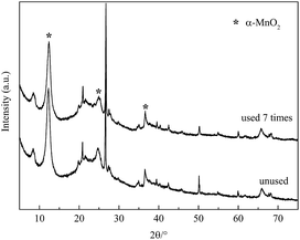 |
| | Fig. 12 XRD patterns of the catalyst before and after being used seven times. | |
Conclusion
Supported α-MnO2 nanosheets were synthesized and investigated in this work. The supported catalyst had high desulfurization efficiency for DBT removal in a model oil employing 30 wt% H2O2 as the oxidant under mild conditions. The influences of process variables such as different solvents, solvent volumes, reaction temperatures and times, as well as catalyst amounts and the H2O2/sulfur molar ratio, were examined. A maximum 97.7% of DBT in a model oil containing 500 ppmw sulfur was removed at 50 °C, H2O2/sulfur molar ratio of 4:1, catalyst/oil ratio of 0.2 g L−1, and duration of 1.5 h. After the reaction, the supported catalyst could be separated from the reaction readily and recycled seven times with an unnoticeable decrease in catalytic activity. Therefore, the prepared catalyst had excellent reusability and could be used for industrial applications on catalytic ODS.
Conflicts of interest
There are no conflicts to declare.
Acknowledgements
This work was supported financially by the Science and Technology Planning Project of Nantong (MS12015040).
Notes and references
- A. M. Dehkordi, M. A. Sobati and M. A. Nazem, Chin. J. Chem. Eng., 2009, 17, 869–874 CrossRef.
- X. Ma, A. Zhou and C. Song, Catal. Today, 2007, 123, 276–284 CrossRef.
- W. Guo, C. Y. Wang, X. Shen and X. P. Lu, Pet. Sci. Technol., 2013, 31, 215–223 CrossRef.
- L. Chen, S. Guo and D. Zhao, Chin. J. Chem. Eng., 2007, 15, 520–523 CrossRef.
- G. Mohebali and A. S. Ball, Int. Biodeterior. Biodegradation, 2016, 110, 163–180 CrossRef.
- S. Aslam, F. Subhan, Z. Yan, P. Peng, K. Qiao, W. Xing, P. Bai, R. Ullah, U. J. Etim, J. Zeng and M. Ikram, Chem. Eng. J., 2016, 302, 239–248 CrossRef.
- S. A. Dharaskar, K. L. Wasewar, M. N. Varma and D. Z. Shende, Environ. Sci. Pollut. Res., 2016, 23, 9284–9294 CrossRef PubMed.
- W. Ding, W. Zhu, J. Xiong, L. Yang, A. Wei, M. Zhang and H. Li, Chem. Eng. J., 2015, 266, 213–221 CrossRef.
- Y. Tian, Y. Yue, Y. Zhi, L. Yan and S. Lu, Energy Fuels, 2015, 29, 618–625 CrossRef.
- W. N. A. W. Mokhtar, W. A. W. A. Bakar, R. Ali and A. A. A. Kadir, Clean Technol. Environ. Policy, 2015, 17, 1487–1497 CrossRef.
- J. Xiao, L. Wu, Y. Wu, B. Liu, L. Dai, Z. Li, Q. Xia and H. Xi, Appl. Energy, 2014, 113, 78–85 CrossRef.
- C. Yang, K. Zhao, Y. Cheng, G. Zeng, M. Zhang, J. Shao and L. Lu, Sep. Purif. Technol., 2016, 163, 153–161 CrossRef.
- N. Zhao, S. Li, J. Wang, R. Zhang, R. Gao, J. Zhao and J. Wang, J. Solid State Chem., 2015, 255, 347–353 CrossRef.
- S. Wei, H. He, Y. Cheng, C. Yang, G. Zeng and L. Qiu, RSC Adv., 2016, 9, 103253–103269 RSC.
- X. Xiao, H. Zhong, C. Zheng, M. Lu, X. Zuo and J. Nan, Chem. Eng. J., 2016, 304, 908–916 CrossRef.
- L. Qiu, Y. Cheng, C. Yang, G. Zeng, Z. Long, S. Wei, K. Zhao and L. Luo, RSC Adv., 2016, 6, 17036–17045 RSC.
- M. Y. Masoomi, M. Bagheri and A. Morsali, Inorg. Chem., 2015, 54, 11269–11275 CrossRef PubMed.
- J. Zhang, G. Wang, L. Zhang, X. Fu and Y. Liu, React. Kinet., Mech. Catal., 2014, 113, 347–360 CrossRef.
- Y. Jia, G. Li and G. Ning, Fuel Process. Technol., 2011, 92, 106–111 CrossRef.
- K. Yazu, T. Miki, Y. Yamamoto, K. Furuya and K. Ukegawa, Energy Fuels, 2001, 15, 1535–1542 CrossRef.
- D. Xie, Q. He, Y. Su, T. Wang, R. Xu and B. Hu, Chin. J. Catal., 2015, 36, 1205–1213 CrossRef.
- S. Xun, W. Zhu, D. Zheng, H. Li, W. Jiang, M. Zhang, Y. Qin, Z. Zhao and H. Li, RSC Adv., 2015, 5, 43528–43536 RSC.
- Y. Li, J. Hu and P. Han, Chin. J. Chem. Eng., 2015, 5, 822–826 CrossRef.
- W. Guo, C. Wang, P. Lin and X. Lu, Appl. Energy, 2011, 88, 175–179 CrossRef.
- K. C. M. Xavier, M. D. S. F. D. Santos, M. R. M. C. Santos, M. E. R. Oliveira, M. W. N. C. Carvalho, J. A. Osajima, E. C. D. Silva Filho, J. A. Osajima and E. C. D. Silva Filho, Mater. Res., 2014, 17, 3–8 CrossRef.
- M. Kim, Y. Hwang and J. Kim, J. Power Sources, 2013, 239, 225–233 CrossRef.
- H. Ma, J. Shen, M. Shi, B. Yan, N. Li and M. Ye, Mater. Res. Bull., 2011, 46, 1461–1466 CrossRef.
- G. Tian, W. Wang, D. Wang, W. Qin and A. Wang, Powder Technol., 2017, 315, 60–67 CrossRef.
- F. Dong, J. Wang, Y. Wang and S. Ren, J. Mater. Chem., 2012, 22, 11093–11100 RSC.
- L. Boudriche, R. Calvet, B. Hamdi and H. Balard, Colloids Surf., A, 2012, 399, 1–10 CrossRef.
- H. Liu, T. Chen, D. Chang, D. Chen, C. Qing, J. Xie and R. L. Frost, J. Therm. Anal. Calorim., 2013, 111, 409–415 CrossRef.
- Z. Zhang, J. C. Jung and N. Yan, Nanoscale, 2016, 8, 19684–19695 RSC.
- Y. Li, H. Xie, J. Wang and L. Chen, Mater. Lett., 2011, 65, 403–405 CrossRef.
- Y. Gao, X. Chen, J. Zhang, H. Asakura, T. Tanaka, K. Teramura, D. Ma and N. Yan, Adv. Mater., 2015, 27, 4688–4694 CrossRef PubMed.
- L. Deng, Y. Xie and G. Zhang, Chin. J. Catal., 2017, 38, 379–388 CrossRef.
- H. Lü, C. Deng, W. Ren and X. Yang, Fuel Process. Technol., 2014, 119, 87–91 CrossRef.
- W. Zhu, P. Wu, L. Yang, Y. Chang, Y. Chao, H. Li, Y. Jiang, W. Jiang and S. Xun, Chem. Eng. J., 2013, 229, 250–256 CrossRef.
- J. Zhang, A. Wang, Y. Wang, H. Wang and J. Gui, Chem. Eng. J., 2014, 245, 65–70 CrossRef.
- A. Akbari, M. Omidkhah and J. T. Darian, Ultrason. Sonochem., 2014, 21, 692–705 CrossRef PubMed.
|
| This journal is © The Royal Society of Chemistry 2018 |
Click here to see how this site uses Cookies. View our privacy policy here. 
 Open Access Article
 This Open Access Article is licensed under a Creative Commons Attribution-Non Commercial 3.0 Unported Licence
 *a and
Ya Lib
*a and
Ya Lib