 Open Access Article
Layer-by-layer assembled polyaniline/carbon nanomaterial-coated cellulosic aerogel electrodes for high-capacitance supercapacitor applications†
Shaoyi Lyu *ab,
Yanping Chenbc,
Shenjie Hanb,
Limin Guob,
Zhilin Chenb,
Yun Lu
 b,
Yuan Chenb,
Na Yangb and
Siqun Wang
 *db
*db
aResearch Institute of Forestry New Technology, Chinese Academy of Forestry, Beijing 100091, China. E-mail: lvsy@caf.ac.cn
bResearch Institute of Wood Industry, Chinese Academy of Forestry, Beijing 100091, China
cBeijing Engineering Research Center of Cellulose and Its Derivatives, School of Materials Science and Engineering, Beijing Institute of Technology, Beijing 100081, China
dCenter for Renewable Carbon, University of Tennessee, Knoxville, Tennessee 37996, USA. E-mail: swang@utk.edu
First published on 10th April 2018
Abstract
Traditional layer-by-layer (LbL) assembled electrodes are mostly multilayer composites formed on two-dimensional membrane materials. In this case, the electroactive material cannot enter the interior of the substrate. With porous aerogels as the substrate, the LbL assembly of the electroactive material into the three-dimensional aerogel skeleton can be realised, greatly improving the utilisation and the electrochemical performance of the electroactive material. To create a promising aerogel electrode for high-performance energy storage devices, we herein report an aerogel based on wood pulp fibre (WPF) and cellulose nanocrystals (CNC), for use as a porous substrate for LbL assembly of nanostructural polyaniline (PANI) and graphene oxide (GO) or carboxylic multi-walled carbon nanotubes (CMCNT). Owing to the uniformly distributed multilayer nanoarchitecture, interpenetrating channels, and hydrophilic character of the cellulosic aerogel substrate, the produced electrodes of (PANI/CMCNT)10 and (PANI/CMCNT)10 both display high specific capacitances, favourable capacitance retention, good cycling stabilities, and structural flexibility. In the three-electrode test, their gravimetric specific capacitances are as high as 716.62 and 636.63 F g−1, respectively. In addition, the assembled symmetric supercapacitors show good areal specific capacitances (1.95 and 1.49 F cm−2) in addition to high areal specific energies (168.64 and 113.57 mW h cm−2, respectively). These results demonstrate that the integration of the LbL-assembled electroactive materials and porous cellulosic aerogel substrate can be a promising strategy to design high-efficiency green energy storage devices.
Introduction
There have been extensive studies on the combination of cellulosic materials and electroactive materials to prepare electrode materials for supercapacitors and lithium ion batteries. The methods include: (1) direct physical mixing of the cellulose with the electroactive material, then filtering or casting the mixture into film;1–4 (2) chemically dissolving the cellulose in ionic liquids, and then mixing it with the electroactive material to prepare a film or aerogel;5–7 and (3) converting the cellulose into nanocellulose, and then physically mixing it with the electroactive material to form a film or aerogel.8–12 Although all these methods are simple, the physical mixing can lead to uneven distribution of electroactive material, a propensity for agglomeration, and poor structural order. Thus, the surface morphology cannot be controlled. More importantly, the electroactive material is mostly embedded in the cellulose matrix and therefore cannot fully contact the electrolyte, so its utilisation rate is extremely low.Currently, electroactive materials can be constructed at the nanoscale for electrochemical purposes, by using the layer-by-layer (LbL) assembly of different carbon nanomaterials and conducting polymers.13–16 LbL assembly can be used to combine materials with different microstructures, including nanorods, nanosheets, nanoparticles, and nanofibres.17,18 Thus, this method has the ability to integrate and modulate the complex functions of different nanomaterials with controlled film composition and structure.19 However, at present, the research of LbL assembly is mainly focused on membrane-like substrate materials, such as ITO-coated glass20–22 and polymer films (PET,23,24 PDMS,25 PLA,26 and nanocellulose film27,28). The electroactive material can only be assembled on the surface of these membrane-like substrate materials to form a multilayer composite film, instead of entering the interior of the substrate materials to create in-depth fusion. One way to overcome this problem is using aerogels as the matrix to allow self-assembly of the electroactive material inside its porous structure. For example, Hamedi et al.29,30 prepared four kinds of functional aerogels with different electroactive materials, by using crosslinked cellulose nanofibrils (CNF) aerogels as a porous scaffold. Using the porous aerogel carrier, it becomes possible to prepare diverse functional materials via the LbL assembly technology.
Here, we report the formation of cellulose aerogel with negative charge from wood pulp fibre (WPF) and cellulose nanocrystals (CNC). Then, the positively charged nanostructural polyaniline (PANI) and the negatively charged graphene oxide (GO) or carboxylic multi-walled carbon nanotubes (CMCNT) were assembled into this aerogel using the LbL assembly technique. The resulting aerogel electrode material showed a uniform, multi-component, and hybrid polymer–inorganic 3D network nanoarchitecture. Since the electroactive material is self-assembled on the fibre or membrane surface of the porous aerogel, very high gravimetric capacitance (∼700 F g−1 in 1 M H2SO4 electrolyte) can be achieved in the electrode material with a low loading (∼10 mg per 1 cm3 aerogel). In this sense, compared with cellulose-based electrode materials prepared by the traditional physical mixing method, those prepared with porous aerogels can greatly improve the utilisation of electroactive materials. These results could inspire new nanostructured electrode materials in the future.
Experimental
Materials
CNC was obtained from the conventional method of acid hydrolysis of cellulose (64 wt% sulfuric acid at 45 °C for 30 min). Wet hardwood WPF that was never dried was provided by Borregaard. GO suspensions (2 mg mL−1, flake diameter < 500 nm) and CMCNT (OD < 8 nm, length 0.5–2 μm, –COOH content 3.86 wt%) were purchased from XFNANO. PANI (emeraldine base, average Mw 50![[thin space (1/6-em)]](https://www.rsc.org/images/entities/char_2009.gif) 000) was purchased from Sigma Aldrich. 1,2,3,4-Butanetetracarboxylic acid (BTCA) and sodium hypophosphite (SHP) were purchased from Aladdin. Dimethylacetamide (DMAc), hydrazine hydrate, hydrochloric acid, and other reagents were of analytical grade and purchased from Beijing Chemical Reagents Company (China).
000) was purchased from Sigma Aldrich. 1,2,3,4-Butanetetracarboxylic acid (BTCA) and sodium hypophosphite (SHP) were purchased from Aladdin. Dimethylacetamide (DMAc), hydrazine hydrate, hydrochloric acid, and other reagents were of analytical grade and purchased from Beijing Chemical Reagents Company (China).
Preparation of the aerogels
An aqueous dispersion of WPF/CNC (w/w, 5![[thin space (1/6-em)]](https://www.rsc.org/images/entities/char_2009.gif) :
:![[thin space (1/6-em)]](https://www.rsc.org/images/entities/char_2009.gif) 1) at a concentration of 1.2 wt% was mixed at 5
1) at a concentration of 1.2 wt% was mixed at 5![[thin space (1/6-em)]](https://www.rsc.org/images/entities/char_2009.gif) :
:![[thin space (1/6-em)]](https://www.rsc.org/images/entities/char_2009.gif) 1 weight ratio with BTCA/SHP (w/w, 2
1 weight ratio with BTCA/SHP (w/w, 2![[thin space (1/6-em)]](https://www.rsc.org/images/entities/char_2009.gif) :
:![[thin space (1/6-em)]](https://www.rsc.org/images/entities/char_2009.gif) 1) using an Ultra-Turrax homogeniser (T25, IKA) for 30 min, and then by an ultrasonic processor (VCX 1500HV, Sonics & Materials Inc.) for another 30 min. The aqueous dispersion was subsequently frozen in cylindrical cuprum moulds in liquid nitrogen bath, followed by freeze-drying in a lyophiliser (LGJ-10D, Four-Ring Science Instrument). Finally, the freeze-dried aerogel was heated at 170 °C for 5 min to create sufficient covalent cross-linking.
1) using an Ultra-Turrax homogeniser (T25, IKA) for 30 min, and then by an ultrasonic processor (VCX 1500HV, Sonics & Materials Inc.) for another 30 min. The aqueous dispersion was subsequently frozen in cylindrical cuprum moulds in liquid nitrogen bath, followed by freeze-drying in a lyophiliser (LGJ-10D, Four-Ring Science Instrument). Finally, the freeze-dried aerogel was heated at 170 °C for 5 min to create sufficient covalent cross-linking.
Preparation of PANI, CMCNT, and GO suspensions
PANI (1 g) was added into DMAc (50 mL) and stirred for about 12 h using the Ultra-Turrax homogeniser. Then, the mixture (5 mL) was added into a dilute HCl solution (pH = 3, 45 mL), and sonicated for 1 h at 900 W in an ice water bath using the VCX 1500HV ultrasonic processor. Finally, the resulting PANI dispersion was diluted to 0.5 mg mL−1 with ultrapure water, and 1 M HCl was used to adjust the pH to 2.5.CMCNT powder (0.1 g) was dispersed in ultrapure water (200 mL), and sonicated at 900 W for 1 h in an ice water bath to yield the CMCNT suspension (0.5 mg mL−1). The purchased GO suspension was diluted to a concentration of 0.5 mg mL−1 in ultrapure water.
Assembly of the aerogel electrodes
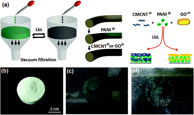
The self-assembly of aerogel electrodes was carried out by a vacuum filtration method, as shown in Fig. 1. This method could force the PANI and CMCNT or GO suspensions to penetrate the entire porous structure of the aerogel. For the PANI/CMCNT aerogel electrode, the PANI suspension was first dropped onto the aerogel and rapidly absorbed by the latter to form a volume-swellable hydrogel. The hydrogel was kept for 15 min, and then the excess PANI suspension was filtered off by vacuum filtration. The volume of the hydrogel will shrink sharply in this step due to the negative pressure. Next, the CMCNT suspension was dropped onto the contracted aerogel, and it rapidly returned to the swollen hydrogel state. The hydrogel was kept for another 15 min and then vacuum-filtered again. This is one cycle in the LbL assembly procedure. After repeating n such cycles, the resultant aerogel electrodes are denoted as “(PANI/CMCNT)n” LbL assemblies.The PANI/GO aerogel electrodes were created using the same method, except that the CMCNT suspension was replaced by the GO suspension. The resulting aerogel electrodes are also shown as “(PANI/GO)n” aerogels.
The assembled aerogels were placed in a large amount of ultrapure water for dialysis treatment in order to remove the residual hydrochloric acid and DMAc, and then freeze-dried after being frozen in liquid nitrogen to obtain the desired aerogel electrodes. In order to improve the electrochemical performance, the PANI/GO aerogels need to be reduced using hydrazine hydrate and ammonia solution in an autoclave at 90 °C for 2 h.
Preparation of all-solid-state supercapacitors
The aerogel electrode was compressed at 1 MPa into an aerogel film for the subsequent assembly of the all-solid-state supercapacitor. The compressed aerogel film was cut to a desired size and then immersed in the PVA/H3PO4 electrolyte for about 1 hour, after which it was allowed to dry at room temperature. Next, two such aerogel film electrodes were gently pressed together to obtain a sandwich structure as the all-solid-state supercapacitor device.Characterisation and electrical measurements
The size and zeta potential of the PANI, CMCNT, and GO particles were measured using a Zetasizer Nano ZS instrument (Malvern Instruments Ltd., UK). Fourier transform infrared (FTIR) spectra were recorded by a Nicolet iS10 spectrometer (Thermo Fisher Scientific Inc., USA). Raman measurement was performed with an inVia confocal Raman microscope with 632.8 nm diode laser excitation at room temperature (Renishaw, UK). X-ray diffraction (XRD) measurement was performed on a D8 Advance instrument with Cu Kα radiation (λ = 0.154 nm, 40 kV, 40 mA) in the 2θ range of 5–60° (Bruker Co., Germany). X-ray photoelectron spectroscopy (XPS) analysis was conducted on an ESCALAB 250Xi instrument with an Al Kα (hν = 1486.6 eV) X-ray source set at 20 mA (Thermo Fisher Scientific Inc., USA). Scanning electron microscopy (SEM) examination was performed using a Hitachi S-4800 field-emission-gun SEM (Japan) at 5.0 kV. Transmission electron microscopy (TEM, Tecnai G2 F30, FEI, USA) was used to characterise the microstructure of the aerogels. The specific surface and pore volume were measured using the multipoint Brunauer–Emmett–Teller (BET) and Barrett–Joyner–Halenda (BJH) method for N2 gas adsorption isotherm analysis (NOVA 1200e Quantachrome, USA). Conductivity was measured using a ST 2253 4-point probe resistivity measurement system (Suzhou Jingge Electronic Co., Ltd, China).Electrochemical measurements were carried out on a CHI 660E electrochemical workstation (Shanghai Chenhua Instrument Co., LTD, China) at room temperature. A three-electrode testing system was employed for the aerogel electrodes using 1 M H2SO4 electrolyte solution, where a saturated calomel electrode (SCE) and Pt electrode were used as the reference and counter electrodes, respectively. The electrochemical measurements of supercapacitor devices were carried out using a two-electrode system.
Cyclic voltammetry (CV) was conducted in the 0–0.8 V range with incremental sweep rates. Galvanostatic charge–discharge (GCD) properties were measured at different current densities with a cut-off voltage of 0–0.8 V. Electrochemical impedance spectroscopy (EIS) was performed from 0.001 to 105 Hz, with an amplitude of 0.005 V referred to the open circuit potential. From the three-electrode tests, the areal and gravimetric specific capacitances (Cs in F cm−2 and Cg in F g−1) were calculated as Cs = (∫IdU)/(vSU) and Cg = 2Im(∫Udt)/(Uf − Ui)2; where I (A), v (V s−1), S (cm2), U (V), t (s), and Im (A g−1) are the current, voltage sweep rate, working area of the electrode, potential with initial and final values of Uf and Ui, discharge time, and current density, respectively.31 For the two-electrode tests, Cs′ = 4(∫IdU)/(vSU) or Cs′′ = 4(IΔt)/(SU), and Cg′ = 4(IΔt)/(mU), where Cs′, Cs′′, and Cg′ are the areal specific capacitance and gravimetric specific capacitance of the supercapacitor devices, respectively. The areal energy E (mW h cm−2) and the areal power P (mW cm−2) of the supercapacitor were obtained according to the expressions E = 1/4(U2Cs′′/2) and P = E/Δt, respectively.
Results and discussion
As a positively charged nanomaterial, the PANI nanoparticles were incorporated into an electrostatic LbL system with a carbon nanomaterial (CMCNT or GO) and complementary negatively charged polyelectrolyte on WPF/CNC aerogel. The PANI prepared in this study appeared as nanoparticles in the acid suspension (pH ∼ 2.5), as shown by the TEM image in Fig. S1a, ESI.† The average particle size was 356.4 nm and the zeta potential was 44.3 mV (Fig. S1d†). The TEM images of CMCNT and GO (Fig. S1b and c†) indicate that they are typical nanotube and nanosheet structures. CMCNT and GO also have average particle sizes of 208.2 and 321.5 nm and zeta potentials of −45.1 mV at pH ∼ 6.9 and −40.6 mV at pH ∼ 6.8, respectively. These data show that these nanomaterials have good nano-size morphology and sufficient surface charge for the LbL assembly.A schematic depiction of the LbL assembly process is displayed in Fig. 1a, and its details are described in the Experimental section. Briefly, PANI nanoparticles and CMCNT or GO were alternately deposited on the porous structure of WPF/CNC aerogel. After the PANI assembly, the white aerogel (Fig. 1b) became dark green (Fig. 1c), which is characteristic of the doped PANI (emeraldine salt). After assembly of CMCNT or GO, the aerogel's colour would become darker and eventually appearing as black, as shown in Fig. 1d. We used WPF/CNC aerogel as the substrate, because CNC itself is a negatively charged substrate, and the micron-scale WPF could provide a large and flexible “frame”. In the formed aerogel system, the nano-scale CNC particles are filled into the gap between the WPF as small and rigid “brackets” (Fig. S2a†). This structure allows the WPF/CNC aerogel to maintain its microstructure without collapsing when subjected to repeated vacuum pumping, even though the BTCA cross-linking degree of WPF/CNC aerogels was only 20%. Although the BTCA cross-linking can increase the negative charge, excessive cross-linking not only seriously decreases the specific surface area of aerogels, but also makes them more brittle. This is because BTCA will undergo esterification with CNC, causing the latter to easily aggregate with each other. In order to balance the many influencing factors, we performed preliminary experiments and determined the optimal degree of BTCA cross-linking to be 20%. The specific surface area and total pore volume of the WPF/CNC aerogels with 20% BTCA cross-linking in this study can reach to 44.68 m2 g−1 and 0.042 cm3 g−1 (Fig. S3†), which is beneficial for the LbL assembly procedure.
The microscopic morphology of WPF/CNC aerogels before and after LbL assembly is shown in Fig. 2. Before LbL assembly, WPF and CNC form an intertwined three-dimensional porous structure (Fig. 2a), and the micron-scaleWPF is wrapped with the nano-fibres (Fig. S2b†) and nano-films formed by CNC (Fig. 2b). Part of the CNC nano-film attached to theWPF surface to form a corrugated membrane structure, and the surface is relatively smooth without granular morphology (Fig. 2c). After the LbL assembly of PANI and CMCNT or GO, the (PANI/CMCNT)10 and (PANI/GO)10 aerogels (Fig. 2d and g, respectively) still maintained the 3D porous morphology. This shows that the structure of aerogels remained intact after 10 cycles of LbL assembly in the aqueous system, and kept the good porous structure. Comparing Fig. 2c, e and h, after LbL assembly, the electroactive nanomaterials are uniformly attached to the surface of corrugatedWPF membrane to form a stacked granular multilayer nanostructure.
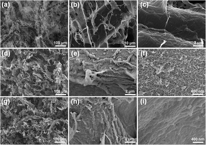 | ||
| Fig. 2 SEM images of (a–c) the WPF/CNC aerogel, (d–f) the (PANI/CMCNT)10 aerogel, and (g–i) the (PANI/GO)10 aerogel at different magnifications. | ||
For the (PANI/CMCNT)10 aerogels, the high-magnification image in Fig. 2f shows that the PANI nanoparticles and CMCNT nanotubes created highly agglomerated and entangled porous nanostructures due to ionic interaction, van der Waals interactions, and capillary forces.21 The microstructure of (PANI/GO)10 aerogels is slightly different, with relatively flat and somewhat more densely packed PANI and GO network nanostructures (Fig. 2i). Since the final layer in the LbL film was GO, the PANI particles are predominately covered by lamellar GO. This highly interpenetrating nanostructure allows the (PANI/CMCNT)10 aerogel to achieve a relatively higher specific surface area (Fig. S3a,† 118.52 m2 g−1) and pore volume (Fig. S3b,† 0.197 cm3 g−1) than the (PANI/GO)10 aerogel (Fig. S3,† 56.04 m2 g−1, 0.168 cm3 g−1), which is favourable for electrochemical performance because of the improved electronic and ionic transport channels.32,33
In addition to WPF, after LbL assembly, the smooth morphology of the nanofibres formed by CNC is similarly attached with multilayer nanomaterials and becomes remarkably rough (Fig. 3a and b). We further analysed the elemental distribution on (PANI/CMCNT)10 and (f) (PANI/GO)10 on CNC nanofibres using energy dispersive spectroscopy (EDS), as shown in Fig. S2e and f.† As indicated, N element was well dispersed within the nanofibrous structure. The TEM image gives additional details about the microstructures of (PANI/CMCNT)10 and (PANI/GO)10 aerogels. Due to the large size of the WPF, the TEM can only observe the CNC. The (PANI/CMCNT)10 aerogel shows intertwined fibrous network structure with a rough surface (Fig. S2c†). Under higher magnification, the CNC nanofibres have an attached layer of PANI and CNT nanoparticles (Fig. 3c). This is consistent with the SEM image in Fig. 3a. The TEM morphology of (PANI/GO)10 aerogels is similar to that of (PANI/GO)10, also showing a random entangled network structure (Fig. S2d†). Likewise, under higher magnification, it is found that the CNC nanofibres are wrapped by larger-scale GO nanosheets, while smaller PANI nanoparticles are harder to observe (Fig. 3d). This is directly related to the last layer of LBL being GO. This micromorphology is also consistent with the SEM image of Fig. 3b.
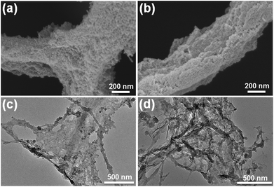 | ||
| Fig. 3 SEM images of (a) (PANI/CMCNT)10 and (b) (PANI/GO)10 on CNC nanofibres. TEM images of (c) (PANI/CMCNT)10 and (d) (PANI/GO)10 on CNC nanofibres. | ||
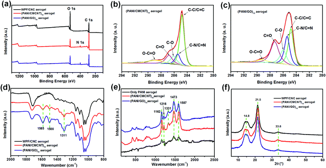
The surface chemistry of WPF/CNC aerogels before and after LbL assembly was investigated using XPS. The survey scan spectra of the three aerogels (Fig. 4a) show that the contents of C, O, and N elements change significantly after LbL assembly. The C/O ratio of the WPF/CNC, (PANI/CMCNT)10, and (PANI/GO)10 aerogels is 1.59, 5.07, and 3.83, respectively (Fig. S4a†). As presented in Fig. 4b and c, and S4b,† the C 1s peak for (PANI/CMCNT)10 aerogel was composed of five peaks with binding energies of 284.8 eV (C![[double bond, length as m-dash]](https://www.rsc.org/images/entities/char_e001.gif) C/C–C), 285.4 eV (C–N/C
C/C–C), 285.4 eV (C–N/C![[double bond, length as m-dash]](https://www.rsc.org/images/entities/char_e001.gif) N), 286.2 eV (C–O), 286.8 eV (C
N), 286.2 eV (C–O), 286.8 eV (C![[double bond, length as m-dash]](https://www.rsc.org/images/entities/char_e001.gif) O), and 288.9 eV (O–C
O), and 288.9 eV (O–C![[double bond, length as m-dash]](https://www.rsc.org/images/entities/char_e001.gif) O). For the (PANI/GO)10 aerogel, these five peaks are located at 284.8, 285.4, 286.1, 287.3, and 289.2 eV, respectively. Meanwhile, for the WPF/CNC aerogels, the C 1s peak was only composed of three peaks with binding energies of 284.8 eV (C
O). For the (PANI/GO)10 aerogel, these five peaks are located at 284.8, 285.4, 286.1, 287.3, and 289.2 eV, respectively. Meanwhile, for the WPF/CNC aerogels, the C 1s peak was only composed of three peaks with binding energies of 284.8 eV (C![[double bond, length as m-dash]](https://www.rsc.org/images/entities/char_e001.gif) C/C–C), 286.3 eV (C–O), and 288.7 eV (C
C/C–C), 286.3 eV (C–O), and 288.7 eV (C![[double bond, length as m-dash]](https://www.rsc.org/images/entities/char_e001.gif) O).14 This demonstrates the good combination of PANI with CMCNT or GO on the WPF/CNC aerogels. Furthermore, the XPS N 1s spectrum is deconvoluted into three peaks to illustrate the electrical properties of PANI (Fig. S4c and d†). There are three component peaks: amine (–NH–) with binding energy centred at 399.9 and 399.6 eV, imine groups (
O).14 This demonstrates the good combination of PANI with CMCNT or GO on the WPF/CNC aerogels. Furthermore, the XPS N 1s spectrum is deconvoluted into three peaks to illustrate the electrical properties of PANI (Fig. S4c and d†). There are three component peaks: amine (–NH–) with binding energy centred at 399.9 and 399.6 eV, imine groups (![[double bond, length as m-dash]](https://www.rsc.org/images/entities/char_e001.gif) NH–) centred at 398.2 and 398.3 eV, and positively charged nitrogen groups (N+) centred at 401.1 eV.21
NH–) centred at 398.2 and 398.3 eV, and positively charged nitrogen groups (N+) centred at 401.1 eV.21
The FTIR spectra of the three aerogels also show the changing chemical functional groups after LbL assembly (Fig. 4d). The prominent peaks of (PANI/CMCNT)10 and (PANI/GO)10 aerogels appear at 1585, 1500, and 1311 cm−1. These peaks are respectively assigned to the N![[double bond, length as m-dash]](https://www.rsc.org/images/entities/char_e001.gif) Q
Q![[double bond, length as m-dash]](https://www.rsc.org/images/entities/char_e001.gif) N stretching, N–B–N stretching (B and Q represent benzenoid and quinoid moieties, respectively), and C–N stretching vibrations with aromatic conjugation, which are all characteristic of PANI.34,35 Raman spectra were measured to further investigate the structural changes of the aerogels. As shown in Fig. 4e, the (PANI/CMCNT)10 and (PANI/GO)10 aerogels show characteristic Raman peaks at 1162 cm−1 for C–H bending of the quinoid ring, 1216 cm−1 for C–H bending of the benzoid ring, 1331 cm−1 for C–N*+ stretching for the radical cation, 1473 cm−1 for C
N stretching, N–B–N stretching (B and Q represent benzenoid and quinoid moieties, respectively), and C–N stretching vibrations with aromatic conjugation, which are all characteristic of PANI.34,35 Raman spectra were measured to further investigate the structural changes of the aerogels. As shown in Fig. 4e, the (PANI/CMCNT)10 and (PANI/GO)10 aerogels show characteristic Raman peaks at 1162 cm−1 for C–H bending of the quinoid ring, 1216 cm−1 for C–H bending of the benzoid ring, 1331 cm−1 for C–N*+ stretching for the radical cation, 1473 cm−1 for C![[double bond, length as m-dash]](https://www.rsc.org/images/entities/char_e001.gif) N bending, and 1587 cm−1 for the C
N bending, and 1587 cm−1 for the C![[double bond, length as m-dash]](https://www.rsc.org/images/entities/char_e001.gif) C stretching of quinoid, displaying the characteristic peaks from both PANI and CMCNT or GO.14,21 In the XRD patterns of aerogels (Fig. 4f), the diffraction peaks at 14.8°, 21.5°, and 33.6° represent the typical cellulose I crystalline structure, while the diffraction peaks of PANI, CMCNT, and GO were all covered by those of WPF and CNC. Overall, these results further confirm the successful LbL assembly of PANI with CMCNT or GO on WPF/CNC aerogels. The conclusions are consistent with the TEM and SEM studies, thereby illustrating the successful construction of multilayer nanomaterials with well-designed microstructure.
C stretching of quinoid, displaying the characteristic peaks from both PANI and CMCNT or GO.14,21 In the XRD patterns of aerogels (Fig. 4f), the diffraction peaks at 14.8°, 21.5°, and 33.6° represent the typical cellulose I crystalline structure, while the diffraction peaks of PANI, CMCNT, and GO were all covered by those of WPF and CNC. Overall, these results further confirm the successful LbL assembly of PANI with CMCNT or GO on WPF/CNC aerogels. The conclusions are consistent with the TEM and SEM studies, thereby illustrating the successful construction of multilayer nanomaterials with well-designed microstructure.
After assembly onto the nanofibre or nanomembrane surface of WPF/CNC aerogel, the electroactive materials of PANI and CMCNT or RGO formed a uniformly distributed nanocomposite with multilayer nanoarchitectures that could improve the electrochemical performance. To confirm this, we first investigated the charge storage capacities of (PANI/CMCNT)10 and (PANI/RGO)10 aerogel electrodes (both assembled with 10 LbL cycles) using a three-electrode cell in 1 M H2SO4 electrolyte. Then, we investigated the performance of aerogel electrodes with varying LbL cycles in a two-electrode system using PVA/H3PO4 gel as the electrolyte.
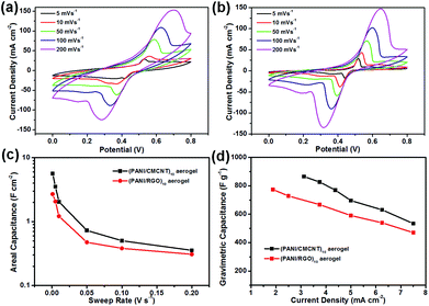
Before measurements, the aerogel electrode was compressed into an aerogel film (Fig. S5a†). The CV data for the (PANI/CMCNT)10 and (PANI/RGO)10 aerogel electrodes are displayed in Fig. 5a and b. Notably, both electrodes exhibited prominent redox peaks that are mainly attributed to the leucoemeraldine/emeraldine and emeraldine/pernigraniline redox reactions of PANI. It should be noted that the carbon materials (CMCNT and RGO) provided not only double-layer capacitance but also some additional pseudocapacitance, since their surface still retained some amount of oxygen-containing functional groups.14,21,36 As the scan rate increased from 5 to 200 mV s−1, the distortion of CV curves became more obvious. The anodic peak shifted from 0.53 to 0.70 V, and the cathodic peak from 0.41 to 0.28 V for the (PANI/CMCNT)10 aerogel electrode, while for the (PANI/RGO)10 aerogel electrode these values are from 0.52 to 0.65 V and 0.44 to 0.31 V, respectively. Both maximum currents increased nonlinearly with scan rate (Fig. S6a and b†), which shows that these electrodes have a mixed nondiffusion- and diffusion-controlled redox process.14,37 The galvanostatic charge/discharge curves of the two aerogel electrodes exhibited curved charge and discharge lines corresponding to pseudocapacitance, a characteristic mainly contributed from the PANI (Fig. S6c and d†).
By comparing the electrochemical properties of the two aerogel electrodes, it is found that the CV curve of (PANI/RGO)10 electrode is more distorted than that of (PANI/CMCNT)10 at the same scanning rate of 5 mV s−1 (Fig. S6e†). Moreover, the (PANI/CMCNT)10 aerogel electrode discharged for a longer time at the same current density of 3.750 mA cm−2 (Fig. S6f†). The EIS curves also show that the interior resistance of (PANI/CMCNT)10 aerogel electrode is less than that of (PANI/RGO)10 (Fig. S5b†). The corresponding equivalent series resistance (ESR) values of the two electrodes are determined to be 1.67 and 11.33 Ω from the Nyquist plots, thereby confirming their relatively small electrical resistance. These results indicate that the (PANI/CMCNT)10 aerogel electrode has relatively better electrolyte accessibility than the (PANI/RGO)10 electrode, and thus is more beneficial to ion transport and electron diffusion. This is consistent with the aforementioned microstructure and specific surface area of the two electrode materials (i.e., the (PANI/CMCNT)10 aerogel electrode has more microscopic porous structure and a higher specific surface area, which is more conducive to diffusion). This difference is also reflected in the capacitance. The calculated areal specific capacitance of the (PANI/CMCNT)10 aerogel electrode through the CV curve is much larger than that of (PANI/RGO)10 (Fig. 5c), reaching 5.63 vs. 2.69 F cm−2 at 1 mV s−1. The gravimetric specific capacitance of the (PANI/CMCNT)10 aerogel electrode, calculated from the discharge curves, is 716.62 F g−1 at a current density of 3.125 mA cm−2 (Fig. 5d), which is again larger than that of (PANI/RGO)10 (636.63 F g−1 at a current density of 1.875 mA cm−2). The capacitances of both electrodes far exceed the best values previously reported for PANI/RGO LbL films,38 and PANI/RGO LbL hollow spheres39 in 1 M H2SO4 electrolyte, and also better than other aerogel electrodes with nanocellulose as substrate.29,40,41 The high specific capacitance of our new aerogel electrodes prepared by the LbL assembly of PANI and CMCNT or RGO demonstrates that the LbL method can build a porous coating with good connectivity and fine nanostructures throughout the whole aerogel network structure, which significantly increases the utilisation of electroactive material and improves the electrochemical performance.
Generally speaking, as the LbL cycle number increases, the mass loading of the electroactive material on the aerogel increases, and the conductivity of the aerogel electrode increases accordingly (Fig. S7†). This is because a higher mass loading means denser packing of electroactive materials and their increased overlap with each other, resulting in more continuous and interconnecting pathways for electron transport in the aerogel electrode. Therefore, we investigated the electrochemical performance of the aerogel electrodes with varying numbers of LbL cycles. Fig. S8† compares the CV data under 20 mV s−1 and GCD data under 1.000 mA cm−2 for the (PANI/CMCNT)n and (PANI/RGO)n aerogel electrodes with different LbL numbers (n). The results show that the current density and regularity of CV curves strengthen as the LbL cycle continued (Fig. S8a and b†), especially for the (PANI/RGO)n aerogel electrode (Fig. S8b†). From the discharge curve, with increasing LbL number, the GCD curve is closer to an isosceles triangle, the time of discharge is prolonged, and the IR drop declines (Fig. S8c and d†). Combined with the results of Fig. S7,† within the scope of this experiment, a higher LbL number not only increases the conductivity and the mass loading in the aerogel electrode, but also significantly improves the electrochemical performance. To this end, below we focus on the electrochemical properties of aerogel electrodes with n = 10.
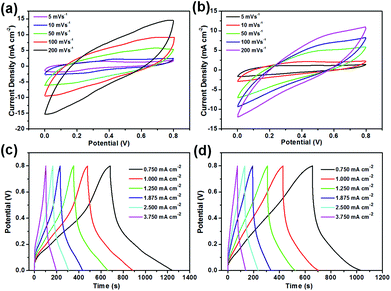
The electrochemical behaviours of symmetric supercapacitors (SCs) containing the (PANI/CMCNT)10 or (PANI/RGO)10 aerogel electrodes were then evaluated in a two-electrode system using PVA/H3PO4 gel as the electrolyte. Both aerogel electrodes exhibited typical pseudocapacitive behaviour without obvious redox peaks as the scan rate increased from 5 to 200 mV s−1 (Fig. 6a and b), and the CV curve was only slightly deformed even at the high scanning rate of 200 mV s−1, especially for (PANI/CMCNT)10 (Fig. 6a). At the same scan rate, the (PANI/CMCNT)10 aerogel electrode had more regular, rectangular CV curves and a larger integrated area than the (PANI/RGO)10 aerogel electrode. These phenomena were also confirmed by the corresponding GCD curves in the current density range from 0.750 to 3.750 mA cm−2 (Fig. 6c and d). At the same current density, the (PANI/CMCNT)10 aerogel electrode exhibited a more regular isosceles triangle shape in the charge–discharge curves and a longer discharge time, compared to that of the (PANI/RGO)10 aerogel electrode. In addition, the EIS curves also showed that (PANI/CMCNT)10 aerogel electrode had a relatively smaller ESR values (22.08 Ω vs. 30.09 Ω for (PANI/RGO)10 aerogel electrode, see Fig. S9a†). All of these results are related to the improved porous nanostructure, higher specific surface area, and higher conductivity and mass loading of the (PANI/CMCNT)10 aerogel electrode. The CV and GCD results also imply that this aerogel electrode displayed relatively fast charge transfer and good rate capability, due to the densely packed electroactive materials onto the porous and lyophilic WPF/CNC aerogels.
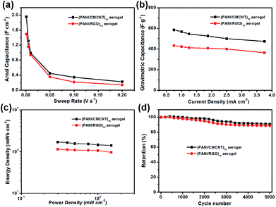
The specific capacitance of the aerogel electrodes also reflected their performance difference. As shown in Fig. 7, the areal specific capacitances for (PANI/CMCNT)10 were all larger than those for (PANI/RGO)10 at the same sweep rate. The values could reach to 1.95 and 1.49 F cm−2, as calculated from the CV curves (Fig. 7a) at a low sweep rate of 1 mV s−1, or reach to 2.11 and 1.42 F cm−2 calculated from the GCD curves (Fig. 7a) at a low current density of 0.75 mA cm−1, respectively. The areal capacitance values of two aerogel electrodes assembled using the LbL method are significantly higher than those of PANI and RGO LbL assembled on CNF film27 as well as other recently reported electrodes with similar electroactive materials (e.g. paper-based graphite/PANI electrodes,42 carbon nanotube/PANI hydrogel film electrodes,43 3D porous RGO/PANI composites,44 and carbon nanotube/PANI nanoribbon paper (ref. 45)). Moreover, the gravimetric capacitances estimated from the discharge process for the (PANI/CMCNT)10 and (PANI/RGO)10 aerogel electrodes were 585.57 and 433.51 F g−1, respectively, at a current density of 0.75 mA cm−2 (Fig. 7b). Interestingly, there was also a slight decline in the rate performance (80.98% and 84.01% capacitance retention for (PANI/CMCNT)10 and (PANI/RGO)10 aerogel electrodes, respectively) when the current density increased to 3.75 mA cm−2. This indicates that the aerogel electrodes can sustainably cover a broad current range and provide favourable power performance.
Fig. 7c is the corresponding Ragone plots calculated from the GCD curves for the two SCs with aerogel electrodes. It shows that the SC made from (PANI/CMCNT)10 aerogel electrodes can deliver a much higher energy density than that from (PANI/RGO)10. More specifically, the maximum areal specific energy of the former reached 168.64 mW h cm−2 at an areal specific power of 0.30 mW cm−2, while those for the latter reached 113.57 mW h cm−2 at the same areal specific power. The long-term cycling performance of the two SCs was tested at a scan rate of 10 mV s−1 (Fig. 7d, S9c and d). After 5000 cycles, the SC based on (PANI/CMCNT)10 aerogel electrode retained 90.73% of its initial capacitance, while that of (PANI/RGO)10 only retained 88.61%, thereby demonstrating that the former was slightly more stable than the latter. The two aerogel electrodes also had good flexibility due to the cellulosic-based skeleton. To test this, their capacitive performance at the normal and bent states was evaluated by CV tests at a sweep rate of 50 mV s−1 (Fig. S10†). The results showed that the capacitive behaviour was basically not affected by bending the electrodes.
Conclusions
In summary, we demonstrated the use of WPF/CNC aerogel as a porous lightweight substrate for the LbL assembly of the electroactive material PANI and CMCNT or GO, in order to produce promising aerogel electrodes for high-performance energy storage devices. Combining the advantages of the uniformly distribution of multi-layered nanoarchitectures formed by PANI, CMCNT or GO on the cellulosic aerogel, and the porous structure and hydrophilic character of the cellulosic aerogel substrate, the resultant (PANI/CMCNT)10 and (PANI/CMCNT)10 aerogel electrodes exhibited high gravimetric specific capacitances (716.62 and 636.63 F g−1, respectively) in the three-electrode test. The assembled symmetric supercapacitors also have very high real specific capacitances (1.95 and 1.49 F cm−2) and good energy density (168.64 and 113.57 mW h cm−2, respectively). Moreover, the aerogel electrodes also showed stable cycling performance, good rate capability, and flexibility. Our work suggests that the use of porous cellulosic aerogel as a substrate for LbL assembly of supercapacitor electrodes will be a promising pathway to create nanostructures for green energy storage applications.Conflicts of interest
There are no conflicts to declare.Acknowledgements
This work was supported by the Special Fund of the Chinese Central Government for Basic Scientific Research Operations in Commonwealth Research Institutes (No. CAFINT2014K02), the Special Fund for Forest Scientific Research in the Public Welfare (No. 201504603), and Tennessee Experimental Station Project (#TEN00510).Notes and references
- L. Jabbour, M. Destro, C. Gerbaldi, D. Chaussy, N. Penazzi and D. Beneventi, J. Mater. Chem., 2012, 22, 3227–3233 RSC.
- W. Zhe, S. Yang, D. W. Wang, L. Feng, J. Du and H. M. Cheng, Adv. Eng. Mater., 2011, 1, 917–922 Search PubMed.
- Z. Gui, H. Zhu, E. Gillette, X. Han, G. W. Rubloff, L. Hu and S. B. Lee, ACS Nano, 2013, 7, 6037–6046 CrossRef CAS PubMed.
- J. X. Feng, S. H. Ye, A. L. Wang, X. F. Lu, Y. X. Tong and G. R. Li, Adv. Funct. Mater., 2015, 24, 7093–7101 Search PubMed.
- S. S. Jeong, N. Böckenfeld, A. Balducci, M. Winter and S. Passerini, J. Power Sources, 2012, 199, 331–335 CrossRef CAS.
- N. Böckenfeld, S. S. Jeong, M. Winter, S. Passerini and A. Balducci, J. Power Sources, 2013, 221, 14–20 CrossRef.
- A. Brandt, S. Pohlmann, A. Varzi, A. Balducci and S. Passerini, MRS Bull., 2013, 38, 554–559 CrossRef CAS.
- S. Leijonmarck, A. Cornell, G. Lindbergh and L. Wagberg, J. Mater. Chem. A, 2013, 1, 4671–4677 CAS.
- L. Jabbour, C. Gerbaldi, D. Chaussy, E. Zeno, S. Bodoardo and D. Beneventi, J. Mater. Chem., 2010, 20, 7344–7347 RSC.
- K. Gao, Z. Shao, J. Li, X. Wang, X. Peng, W. Wang and F. Wang, J. Mater. Chem. A, 2013, 1, 63–67 CAS.
- Q. Zheng, Z. Cai, Z. Ma and S. Gong, ACS Appl. Mater. Interfaces, 2015, 7, 3263–3271 CAS.
- X. Yang, K. Shi, I. Zhitomirsky and E. D. Cranston, Adv. Mater., 2015, 27, 6104–6109 CrossRef CAS PubMed.
- J. Luo, Y. Chen, Q. Ma, R. Liu and X. Liu, J. Mater. Chem. C, 2014, 2, 4818–4827 RSC.
- J. W. Jeon, S. Kwon and J. Lutkenhaus, J. Mater. Chem. A, 2015, 3, 3757–3767 CAS.
- J. Luo, Y. Chen, Q. Ma, R. Liu and X. Liu, RSC Adv., 2013, 3, 17866–17873 RSC.
- J. Luo, J. Lai, N. Zhang, Y. Liu, R. Liu and X. Liu, ACS Sustainable Chem. Eng., 2016, 4, 1404–1413 CrossRef CAS.
- F. X. Xiao, M. Pagliaro, Y. J. Xu and B. Liu, Chem. Soc. Rev., 2016, 45, 3088–3121 RSC.
- W. A. Marmisollé and O. Azzaroni, Nanoscale, 2016, 8, 9890–9918 RSC.
- J. J. Richardson, M. Björnmalm and F. Caruso, Science, 2015, 348, aaa2491 CrossRef PubMed.
- W. A. Marmisollé, E. Maza, S. Moya and O. Azzaroni, Electrochim. Acta, 2016, 210, 435–444 CrossRef.
- M. N. Hyder, S. W. Lee, F. Ç. Cebeci, D. J. Schmidt, S. H. Yang and P. T. Hammond, ACS Nano, 2011, 5, 8552–8561 CrossRef CAS PubMed.
- S. Shariki, S. Y. Liew, W. Thielemans, D. A. Walsh, C. Y. Cummings, L. Rassaei, M. J. Wasbrough, K. J. Edler, M. J. Bonné and F. Marken, J. Solid State Electrochem., 2011, 15, 2675–2681 CrossRef CAS.
- S. T. Han, Y. Zhou, C. Wang, L. He, W. Zhang and V. A. Roy, Adv. Mater., 2013, 25, 872–877 CrossRef CAS PubMed.
- P. G. Su and C. F. Chiou, Sens. Actuators, B, 2014, 200, 9–18 CrossRef CAS.
- S. W. Lee, B.-S. Kim, S. Chen, Y. Shao-Horn and P. T. Hammond, J. Am. Chem. Soc., 2009, 131, 671–679 CrossRef CAS PubMed.
- C. Aulin, E. Karabulut, A. Tran, L. Wågberg and T. Lindström, ACS Appl. Mater. Interfaces, 2013, 5, 10395–10396 CAS.
- X. Wang, K. Gao, Z. Shao, X. Peng, X. Wu and F. Wang, J. Power Sources, 2014, 249, 148–155 CrossRef CAS.
- K. Gao, Z. Shao, X. Wu, X. Wang, Y. Zhang, W. Wang and F. Wang, Nanoscale, 2013, 5, 5307–5311 RSC.
- M. Hamedi, E. Karabulut, A. Marais, A. Herland, G. Nyström and L. Wågberg, Angew. Chem., Int. Ed., 2013, 52, 12038–12042 CrossRef CAS PubMed.
- G. Nyström, A. Marais, E. Karabulut, L. Wågberg, Y. Cui and M. M. Hamedi, Nat. Commun., 2015, 6, 7259 CrossRef PubMed.
- H. Li, L. Mcrae, C. J. Firby, M. Al-Hussein and A. Y. Elezzabi, Nano Energy, 2018, 47, 130–139 CrossRef CAS.
- S. Q. Fan, B. Fang, J. H. Kim, J. J. Kim, J. S. Yu and J. Ko, Appl. Phys. Lett., 2010, 96, 053503 CrossRef.
- B. Fang, H. Zhou and I. Honma, J. Phys. Chem. B, 2006, 110, 4875–4880 CrossRef CAS PubMed.
- L. Zhang, D. Huang, N. Hu, C. Yang, M. Li, H. Wei, Z. Yang, Y. Su and Y. Zhang, J. Power Sources, 2017, 342, 1–8 CrossRef CAS.
- C. Yang, C. Chen, Y. Pan, S. Li, F. Wang, J. Li, N. Li, X. Li, Y. Zhang and D. Li, Electrochim. Acta, 2015, 182, 264–271 CrossRef CAS.
- S. Y. Kim, J. Hong, R. Kavian, S. W. Lee, M. N. Hyder, S. H. Yang and P. T. Hammond, Energy Environ. Sci., 2013, 6, 888–897 CAS.
- L. Shao, J. W. Jeon and J. Lutkenhaus, J. Mater. Chem. A, 2013, 1, 7648–7656 CAS.
- N. A. Kumar and J. B. Baek, Chem. Commun., 2014, 50, 6298–6308 RSC.
- T. Lee, T. Yun, B. Park, B. Sharma, H. K. Song and B. S. Kim, J. Mater. Chem., 2012, 22, 21092–21099 RSC.
- J. Erlandsson, V. L. Durán, H. Granberg, M. Sandberg, P. A. Larsson and L. Wågberg, Appl. Mater. Today, 2016, 5, 246–254 CrossRef.
- X. Zhang, Z. Lin, B. Chen, W. Zhang, S. Sharma, W. Gu and Y. Deng, J. Power Sources, 2014, 246, 283–289 CrossRef CAS.
- B. Yao, L. Yuan, X. Xiao, J. Zhang, Y. Qi, J. Zhou, J. Zhou, B. Hu and W. Chen, Nano Energy, 2013, 2, 1071–1078 CrossRef CAS.
- S. Zeng, H. Chen, F. Cai, Y. Kang, M. Chen and Q. Li, J. Mater. Chem. A, 2015, 3, 23864–23870 CAS.
- Q. Zhou, Y. Li, L. Huang, C. Li and G. Shi, J. Mater. Chem. A, 2014, 2, 17489–17494 CAS.
- D. Ge, L. Yang, L. Fan, C. Zhang, X. Xiao, Y. Gogotsi and S. Yang, Nano Energy, 2015, 11, 568–578 CrossRef CAS.
Footnote |
| † Electronic supplementary information (ESI) available: Fig. S1–S10. See DOI: 10.1039/c8ra01754a |
| This journal is © The Royal Society of Chemistry 2018 |

