DOI:
10.1039/C8RA01720D
(Paper)
RSC Adv., 2018,
8, 14806-14811
Preparation of metallic monolithic Pt/FeCrAl fiber catalyst by suspension spraying for VOCs combustion
Received
27th February 2018
, Accepted 5th April 2018
First published on 18th April 2018
Abstract
We report a facile and general strategy for the preparation of metallic monolithic catalysts. Our strategy involved subjecting the surfaces of FeCrAl fibers to thermal treatment and the spraying of Pt nanoparticles suspension liquid. The catalyst exhibited high catalytic activity and good stability in the combustion of volatile organic compounds to CO2 and H2O at mild temperature. The exceptional activity of the catalyst can be attributed to the well-adhered alumina coating that formed on the surfaces of the FeCrAl fibers after thermal treatment and the highly dispersed Pt nanoparticles on the surface of the alumina coating.
1. Introduction
As one of the major components of air pollution, volatile organic compounds (VOCs) are both precursors of ozone and photochemical smog and substances that are toxic to human health.1–4 One of the most effective and economically feasible VOC removal technologies is catalytic combustion because catalytic oxidation leads to degradation of VOCs to CO2 and H2O and it is suitable for operation with dilute VOC effluent streams (<1% VOCs).5–8 Monolithic catalysts are widely used in catalytic combustion due to their good attrition resistance and very low pressure drop even under high flow rate. Monoliths are commonly composed of ceramics or metallic materials.9,10 Metallic materials exhibit higher thermal conductivity and mechanical resistance, better electrical conductivity, and lower manufacturing costs than ceramic materials.11,12 Given these advantages, the application of metallic substrates as catalyst supports is becoming increasingly common.13–15 Monolithic catalysts are prepared through electrophoretic deposition,16 anodisation,17 or steam-only oxidation.18 Lu et al. reported a facile, versatile, and cost-effective one-step route for the fabrication of a composite system of hierarchically structured AlOOH 2D-nanosheets on a paper-like 3D network based on Al-fibers. Their method is aided by the steam-only oxidation of Al. The Al-fiber@ns-AlOOH@Pd catalyst presents high intrinsic activity for the oxidative coupling of CO to DMO.19
However, several important issues in the fabrication of metallic monolithic catalysts for VOC combustion remain unresolved. These issues include (1) the process complexity and poor adhesion of conventional wash-coating methods20–23 and (2) the limitation of active component loading due to the shape of the carrier. The preparation flow of the metallic monolithic catalyst is cumbersome: the active species is loaded through impregnation or through a slurry, which is prepared from a powder catalyst and directly coated on the surface of a metallic substrate; then, the monolithic catalyst is obtained through activation treatment. Existing methods for the fabrication of metallic monolithic catalysts require complex and enormous effort to load the active species on the catalyst supports. Nevertheless, active noble metal nanoparticles (NPs) prepared in liquid form can be randomly loaded through a simple spraying method. Moreover, the deactivated catalyst will not require replacement because it can be reactivated through respraying. This method is very economic and convenient, and it can save raw material costs.
Herein, we synthesized Pt NPs dispersion suspension via solvent-thermal method.24–26 A well-adhered alumina coating formed on the surface of FeCrAl fibers after thermal treatment at 950 °C in O2 atmosphere and active NPs were loaded on FeCrAl fibers through simple spraying. Pt NPs were highly dispersed on the surface of the metallic substrate with a monomolecular membrane structure and were firmly bonded on the metallic substrate after calcination (Fig. 1). We evaluated the catalytic performance of the as-synthesized catalyst in the catalytic combustion of toluene, which was used as a model VOC. Our catalyst can exhibit activity toward other VOCs and may enable the significant advancement of VOC removal technologies.27,28
 |
| | Fig. 1 The scheme for preparing monolithic Pt/FeCrAl fiber catalyst by suspension spraying. | |
2. Experimental section
2.1 Catalyst preparation
Dinitrodiammineplatinum ammoniacal (DPA, 34.6 mg) was mixed with 3 mL oleyl amine (OA) and 2 mL oleic acid (OC) in a three-necked flask equipped with a condenser and a stir bar, followed by heating and holding at 200 °C for 3 h under flowing N2 atmosphere. The particles thus formed were purified by precipitation in ethanol, centrifuged (6000 rpm, 5 min), washed with ethanol, and re-dispersed in 10 mL n-hexane.
The FeCrAl fiber (∼1.3 mm in thickness) consisting of 7% Al and 85 vol% voids was utilized as the substrate, which was taken from Kunshan Fangdou Net-structured Material Co. Ltd. (China). The FeCrAl fiber was machined to 6 circular chips (15 mm in diameter, about 2.0 g). Then, FeCrAl fiber was immersed in acetone, 10 wt% NaOH, and 10 wt% HNO3 with ultrasonic treatment for 30 min, in sequence. Subsequently, FeCrAl fiber was calcined in O2 atmosphere at 950 °C for 3 h. A ready-made Pt nanoparticles dispersion liquid was supported on FeCrAl fiber by spraying; then, the monolithic catalyst was dried at 110 °C for 2 h and calcined at 500 °C for 5 h. The loading of Pt was 0.1 wt% (it refers to theoretical value), the monolithic catalyst is denoted as 0.1Pt/FeCrAl fiber.
2.2 Catalyst characterization
Transmission electron microscopy (TEM) images were taken on a Tecnai G2 F30 S-Twin (Philips-FEI, Netherlands) transmission electron microscope at acceleration voltage of 200 kV. The samples were dispersed in ethanol assisted by an ultrasonic technique. Scanning electron microscopy (SEM) and energy-dispersive X-ray spectroscopy (EDS) analysis were performed on a Hitachi-SU8010 SEM with acceleration voltage of 5 kV for imaging and 15 kV for EDS collection. The X-ray diffraction (XRD) patterns were recorded on an X'pert PRO diffractometer (PAN-alytical, Netherlands) using Cu Kα radiation at a generator voltage of 40 kV and tube current of 40 mA. The samples were scanned in the 2θ range of 10–80° with scanning speed of 0.02° s−1. Diffraction peaks were compared with the standard Joint Committee on Powder Diffraction Standards (JCPDS) database reported by the International Centre for Diffraction Data (ICDD). The adhesion of samples was evaluated using ultrasound tests by immersing the samples in water and applying ultrasound for 1 h. After the samples were dried at 110 °C for 2 h and calcined at 500 °C for 2 h, the weight loss was measured.
2.3 Catalytic activity measurement
The activities of catalysts were tested for VOC catalytic combustion in a fixed-bed stainless steel tubular reactor (internal diameter 16 mm and length 350 mm). In each test run, circular chips of the metallic monolithic catalyst were packed layer-by-layer into the stainless steel tubular reactor, while a K-type thermocouple was placed in the middle of the reactor. For this experiment, we used 2.0 g of catalyst with a total flow rate of the feed stream at 347 mL min−1, providing a space velocity of 10![[thin space (1/6-em)]](https://www.rsc.org/images/entities/char_2009.gif) 000 mL h−1 g−1. The feed stream containing 2500 ppm VOCs was generated by bubbling air through a saturator containing pure VOCs chilled in an ice-water isothermal bath, and then diluted with another air stream by the mass flow controller. The concentration of VOCs at the outlet of the reactor was monitored with a gas chromatograph (Kexiao, GC1620) equipped with a flame ionization detector (FID). The concentration of the oxidative product (CO2) was monitored with a mass spectrograph (MKS Cirrus 2). The removal of VOCs was calculated on the basis of the VOCs consumption. The removal efficiency of VOCs was calculated using the following equation:
000 mL h−1 g−1. The feed stream containing 2500 ppm VOCs was generated by bubbling air through a saturator containing pure VOCs chilled in an ice-water isothermal bath, and then diluted with another air stream by the mass flow controller. The concentration of VOCs at the outlet of the reactor was monitored with a gas chromatograph (Kexiao, GC1620) equipped with a flame ionization detector (FID). The concentration of the oxidative product (CO2) was monitored with a mass spectrograph (MKS Cirrus 2). The removal of VOCs was calculated on the basis of the VOCs consumption. The removal efficiency of VOCs was calculated using the following equation:
VOCs conversion (%) = [VOCs]in − [VOCs]out/[VOCs]in × 100%.
3. Results and discussion
3.1 TEM characterization
Fig. 2 shows TEM images of the Pt NPs, which appear spherical in shape with low aggregation and narrow size distribution.29,30 The average sizes of Pt NPs were in the range of 2–4 nm. The monodispersed structure of Pt NPs promoted their dispersal in liquid. Simple spraying was used to randomly load the active species in the VOCs purification system. In addition, the Pt NPs dispersion liquid was extremely stable. It could be stored for 10–30 days without delamination and sol destruction. The storage behavior of the Pt NPs dispersion liquid indicated that it could be continuously used for long periods without changing (Fig. 3). Furthermore, this method is generally applicable and could be easily applied with the dip-coating method. Notably, the low Pt content required for catalyst loading decreased the cost.
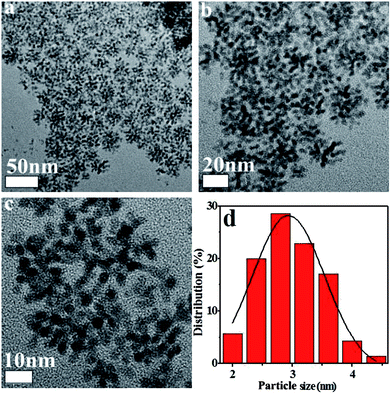 |
| | Fig. 2 TEM images of Pt NPs (a–c) and corresponding size histograms (d). | |
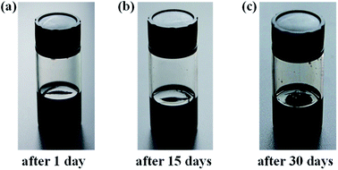 |
| | Fig. 3 Photographs of the as-prepared Pt NPs dispersion liquid after 1 day (a), 15 days (b), and 30 days (c). | |
3.2 SEM characterization
To promote anchoring of the coating to the metallic substrate and to increase the exposed area of the catalyst, FeCrAl fiber was thermally treated at 950 °C for 3 h in O2 atmosphere. To confirm that the applied thermal treatments enabled the formation of a uniform rough surface on the FeCrAl fiber, the morphology and composition of the fibers were studied. Fig. 4 and Table 1 show SEM micrographs and EDS analyses of the surfaces of the untreated and treated FeCrAl fibers. SEM micrographs of the untreated FeCrAl fiber are shown in Fig. 4a. The untreated FeCrAl fiber exhibited slightly cracked smooth surfaces. Additionally, the mass percentages of the elements (Fe, Cr and Al) reported by EDS analysis were similar to those reported by the manufacturers. Fig. 4b shows SEM micrographs of the treated (calcined at 950 °C for 3 h in O2 atmosphere) FeCrAl fiber, which showed the growth of uniformly roughened surfaces.22 Given that the bulk aluminum had a high chemical potential and was likely to be oxidized by oxygen, it easily migrated from the bulk to the surface and reacted with oxygen to form alumina whiskers.31–33 In addition, the EDS analysis results of the thermally treated fibers indicated significant changes to the mass percentages of each element. Clearly, the percentages of Al and O increased, while that of Fe decreased because of the formation of the alumina layer by thermal treatment.34,35 The well-adhered alumina coating promoted firm bonding of the active species to the metallic substrate. SEM micrographs of the monolithic catalyst are presented in Fig. 4c. The images show that the Pt catalyst formed a homogeneous surface on the whiskers or pores. The addition of Pt to the FeCrAl fiber was supported by the percentages reported by EDS analysis, which detected Pt content of approximately 13%. This finding indicated that thermal treatment increased the exposed area of the FeCrAl fiber. This effect ensured catalytic activity by promoting the even dispersion of NPs. Moreover, ultrasound tests were conducted to confirm adherence between the wash-coated and active phases. The total weight losses of the samples were only 0.9 and 0.6 wt%. These results indicated excellent adhesion between the wash-coated and active phases.
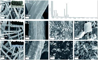 |
| | Fig. 4 SEM images (EDS results) of FeCrAl fiber (a), calcined FeCrAl fiber (b), 0.1Pt/FeCrAl fiber (c). | |
Table 1 Atomic composition of the sample determined by X-EDS
| Sample |
Element |
Weight/% |
Atomic/% |
| FeCrAl fiber |
Fe |
71.27 |
65.74 |
| Cr |
22.41 |
22.20 |
| Al |
6.32 |
12.06 |
| Calcined FeCrAl fiber |
Fe |
30.75 |
15.93 |
| Cr |
11.53 |
6.42 |
| Al |
36.30 |
38.92 |
| O |
21.42 |
38.74 |
| 0.1Pt/FeCrAl fiber |
Fe |
35.79 |
23.36 |
| Cr |
4.67 |
3.44 |
| Al |
29.15 |
24.36 |
| O |
16.71 |
41.35 |
| Pt |
13.68 |
7.49 |
3.3 XRD characterization
The crystal phases of samples were identified by XRD. Fig. 5 shows the diffraction patterns of FeCrAl fiber before and after the treatments. XRD patterns of untreated FeCrAl fiber confirmed the presence of Fe–Cr alloys of ferrite type (PDF 54-0331). However, no diffraction peaks of Al were detected because the content of Al is very low. After calcination treatment at 950 °C, the formation of the crystalline phase Fe2AlCr (PDF 54-0387) was found. This indicated that the percentage of Al increased after calcination; as confirmed from EDS analysis. Moreover, no diffraction peaks of alumina were detected, indicating high dispersion of the alumina layer. It should be noted that no Pt XRD peaks were observed for the 0.1Pt/FeCrAl fiber catalyst, indicating the feature of highly dispersed Pt. Indeed, the TEM image clearly shows that Pt is highly dispersed with average particle size of only 2–4 nm.
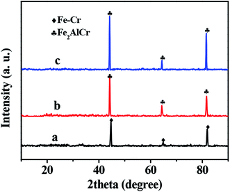 |
| | Fig. 5 XRD patterns of FeCrAl fiber (a), calcined FeCrAl fiber (b), 0.1Pt/FeCrAl fiber (c). | |
3.4 Activity test
The catalytic activities of the samples in toluene combustion were tested under the base condition of toluene inlet concentration of 2500 ppm and WHSV of 10![[thin space (1/6-em)]](https://www.rsc.org/images/entities/char_2009.gif) 000 mL h−1 g−1; the results are presented in Fig. 6a. In the blank experiment (without Pt), no distinct toluene conversion was detected below 300 °C and gas chromatography (GC) detected the presence of other organic compounds in the gaseous product. These results indicated that the direct thermal oxidation of toluene under test conditions and in the absence of active species is negligible.36 In contrast, the 0.1Pt/FeCrAl fiber catalyst achieved complete toluene conversion (>99%) at temperatures exceeding 280 °C. This result, in addition to SEM and TEM observations, indicated that catalytic activity improved with the formation of a well-adhered alumina coating on the surfaces of the FeCrAl fiber through thermal treatment and that 2–4 nm Pt NPs were highly dispersed on the surfaces of the alumina coating. In addition, mass spectroscopy (MS) results showed that the catalyst had nearly 100% selectivity for CO2 at a temperature of 280 °C (Fig. 6b). The ignition curves could be represented either by following the decrease in the toluene signal or by following the increase in CO2 signal.11 Furthermore, on-line MS did not detect CO during the reaction. This result indicated that our catalyst has high selectivity for CO2.
000 mL h−1 g−1; the results are presented in Fig. 6a. In the blank experiment (without Pt), no distinct toluene conversion was detected below 300 °C and gas chromatography (GC) detected the presence of other organic compounds in the gaseous product. These results indicated that the direct thermal oxidation of toluene under test conditions and in the absence of active species is negligible.36 In contrast, the 0.1Pt/FeCrAl fiber catalyst achieved complete toluene conversion (>99%) at temperatures exceeding 280 °C. This result, in addition to SEM and TEM observations, indicated that catalytic activity improved with the formation of a well-adhered alumina coating on the surfaces of the FeCrAl fiber through thermal treatment and that 2–4 nm Pt NPs were highly dispersed on the surfaces of the alumina coating. In addition, mass spectroscopy (MS) results showed that the catalyst had nearly 100% selectivity for CO2 at a temperature of 280 °C (Fig. 6b). The ignition curves could be represented either by following the decrease in the toluene signal or by following the increase in CO2 signal.11 Furthermore, on-line MS did not detect CO during the reaction. This result indicated that our catalyst has high selectivity for CO2.
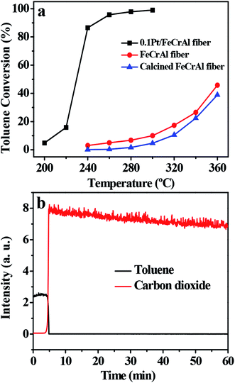 |
| | Fig. 6 Light-off curves of toluene catalytic combustion (a). MS curves of toluene catalytic combustion (temperature = 280 °C) (b). Other conditions: toluene concentration 2500 ppm and WHSV 10![[thin space (1/6-em)]](https://www.rsc.org/images/entities/char_2009.gif) 000 mL h−1 g−1. 000 mL h−1 g−1. | |
3.5 Stability test
To examine stability of the catalyst, we performed on-stream toluene combustion at 280 °C and WHSV of 10![[thin space (1/6-em)]](https://www.rsc.org/images/entities/char_2009.gif) 000 mL h−1 g−1. The results are shown in Fig. 7. Clearly, the conversion rate of toluene was maintained at 100% and catalytic activity did not decrease during 600 min of on-stream reaction. This result suggested that the catalyst has excellent stability and can be applied in the industrial combustion of VOCs.
000 mL h−1 g−1. The results are shown in Fig. 7. Clearly, the conversion rate of toluene was maintained at 100% and catalytic activity did not decrease during 600 min of on-stream reaction. This result suggested that the catalyst has excellent stability and can be applied in the industrial combustion of VOCs.
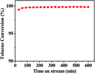 |
| | Fig. 7 The stability of toluene combustion over 0.1Pt/FeCrAl fiber (T = 280 °C). Other conditions: toluene concentration 2500 ppm and WHSV 10![[thin space (1/6-em)]](https://www.rsc.org/images/entities/char_2009.gif) 000 mL h−1 g−1. 000 mL h−1 g−1. | |
3.6 Applicability test
VOCs include alkanes, alcohols, ketones, esters and nitrogen-containing compounds.7,37 To confirm that the catalyst can be applied in the catalytic combustion of other VOCs, we tested the activities of the catalyst in the combustion of ethyl acetate, acetone, n-hexane, isopropyl alcohol (IPA) and N,N-dimethylformamide (DMF). The catalytic performance of 0.1Pt/FeCrAl fiber in VOC combustion is shown in Fig. 8. The temperatures for VOC conversion over 0.1Pt/FeCrAl fiber catalyst for 10% (T10), 50% (T50) and 90% (T90) of total conversion are summarized in Table 2. We conclude that the catalytic activities of our catalyst for VOC combustion are hydrocarbon (nitrogen) > oxygenated compounds because hydrocarbon VOCs were strongly absorbed on the Pt catalyst and were quickly activated. These behaviors are similar to those reported in the literature.7,38 In addition, it can be illustrated that our catalyst can be applied to the catalytic combustion of different types of VOCs.
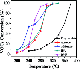 |
| | Fig. 8 Light-off curves of VOC catalytic combustion over 0.1Pt/FeCrAl fiber. Other conditions: VOC concentration of 2500 ppm and WHSV of 10![[thin space (1/6-em)]](https://www.rsc.org/images/entities/char_2009.gif) 000 mL h−1 g−1. 000 mL h−1 g−1. | |
Table 2 Comparison of catalytic activity of 0.1Pt/FeCrAl fiber for VOC combustion
| VOCs |
T10/°C |
T50/°C |
T90/°C |
| Toluene |
213 |
235 |
242 |
| DMF |
228 |
250 |
276 |
| n-Hexane |
214 |
238 |
295 |
| IPA |
212 |
280 |
298 |
| Acetone |
230 |
282 |
300 |
| Ethyl acetate |
280 |
350 |
374 |
3.7 Effect of space velocity
Space velocity is an important parameter for the practical application of catalysts.39 To achieve high VOC combustion efficiency a high space velocity is required for catalysts.36 Hence, the catalytic behavior of the 0.1Pt/FeCrAl fiber in the catalytic combustion of toluene under three different WHSV values was tested (Fig. 9).40 Increasing the WHSV values decreased the toluene conversion at the same reaction temperature. This result may be attributed to the shortened residence time of toluene in the catalyst bed at high WHSV. Nevertheless, the result suggested that the catalyst could be used to catalyze the conversion of high VOC fluxes. Thus, our catalyst has considerable application potential in the environmental catalysis field.
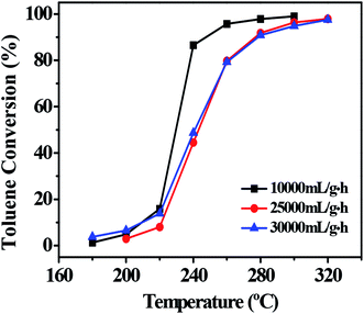 |
| | Fig. 9 Effect of space velocity on toluene combustion over 0.1Pt/FeCrAl fiber. Other conditions: toluene concentration of 2500 ppm. | |
4. Conclusions
Highly dispersed Pt NPs dispersion liquid was prepared via the solvent-thermal method. A well-adhered alumina layer was formed on the surfaces of FeCrAl fibers through thermal treatment. Then, the supported catalyst was fabricated by simply spraying the dispersion liquid on the FeCrAl fibers. Active species were randomly loaded on the surfaces of FeCrAl fibers by spraying. In addition, the catalyst with Pt loading of 0.1 wt% delivered 100% toluene conversion and high CO2 selectivity at the space velocity of 10![[thin space (1/6-em)]](https://www.rsc.org/images/entities/char_2009.gif) 000 mL h−1 g−1. Moreover, the catalyst was stable for at least 600 min without deactivation. The intrinsic activity of the catalyst is intimately related to the high dispersion of 2–4 nm Pt NPs on the surfaces of the alumina coating. Furthermore, we believe that this strategy will provide a new route for the preparation and application of environmental metallic monolithic catalysts.
000 mL h−1 g−1. Moreover, the catalyst was stable for at least 600 min without deactivation. The intrinsic activity of the catalyst is intimately related to the high dispersion of 2–4 nm Pt NPs on the surfaces of the alumina coating. Furthermore, we believe that this strategy will provide a new route for the preparation and application of environmental metallic monolithic catalysts.
Conflicts of interest
There are no conflicts to declare.
Acknowledgements
This study was supported by the Natural Science Foundation of China (No. 21506194, No. 21676255), the Natural Science Foundation of Zhejiang Province (No. Y16B070011), and the Commission of Science and Technology of Zhejiang province (No. 2017C03007, No. 2017C33106).
Notes and references
- H. Wang, W. Yang, P. Tian, J. Zhou, R. Tang and S. Wu, Appl. Catal., A, 2017, 529, 60–67 CrossRef CAS.
- H. Lu, Y. Zhou, W. Han, H. Huang and Y. Chen, Catal. Sci. Technol., 2013, 3, 1480–1484 CAS.
- S. Scire, S. Minico, C. Crisafulli, C. Satriano and A. Pistone, Appl. Catal., B, 2003, 40, 43–49 CrossRef CAS.
- H. Huang, Y. Xu, Q. Feng and D. Y. Leung, Catal. Sci. Technol., 2015, 5, 2649–2669 CAS.
- B. Li, J. Wang and H. Gong, Catal. Today, 2009, 148, 81–87 CrossRef.
- S. Xie, Y. Liu, J. Deng, J. Yang, X. Zhao, Z. Han and H. Dai, Catal. Sci. Technol., 2018, 8, 806–816 CAS.
- M. S. Kamal, S. A. Razzak and M. M. Hossain, Atmos. Environ., 2016, 140, 117–134 CrossRef CAS.
- Y. Wang, L. Guo, M. Chen and C. Shi, Catal. Sci. Technol., 2018, 8, 459–471 CAS.
- W. Zhang and D. Wu, Ceram. Int., 2016, 42, 16563–16570 CrossRef.
- K. S. Yang, J. S. Choi and J. S. Chung, Catal. Today, 2004, 97, 159–165 CrossRef CAS.
- N. Burgos, M. Paulis, M. M. Antxustegi and M. Montes, Appl. Catal., B, 2002, 38, 251–258 CrossRef CAS.
- W. Fei, S. C. Kuiry and S. Seal, Oxid. Met., 2004, 62, 29–44 CrossRef CAS.
- L. M. Martinez, O. Sanz, M. I. Dominguez, M. A. Centeno and J. A. Odriozola, Chem. Eng. J., 2009, 148, 191–200 CrossRef.
- M. Valentini, G. Groppi, C. Cristiani, M. Levi, E. Troncoin and P. Forzatti, Catal. Today, 2001, 69, 307–314 CrossRef CAS.
- S. Cimino, A. Gambriasi, L. Lisi, G. Mancino, M. Musiani, L. Vázquez-Gómez and E. Verlato, Chem. Eng. J., 2016, 285, 276–285 CrossRef CAS.
- H. Sun, X. Quan, S. Chen, H. M. Zhao and Y. Zhao, Appl. Surf. Sci., 2007, 253, 3303–3310 CrossRef CAS.
- O. Sanz, F. J. Echave, M. Sánchez, A. Monzón and M. Montes, Appl. Catal., A, 2008, 340, 125–132 CrossRef CAS.
- C. Wang, L. Han, P. Chen, G. Zhao, Y. Liu and Y. Lu, J. Catal., 2016, 337, 145–156 CrossRef CAS.
- C. Wang, L. Han, Q. Zhang, Y. Li, G. Zhao, Y. Liu and Y. Lu, Green Chem., 2015, 17, 3762–3765 RSC.
- Y. Diaz, A. Sevilla, A. Mónaco, F. J. Méndez, P. Rosales, L. Garcia and J. L. Brito, Fuel, 2013, 110, 235–248 CrossRef CAS.
- J. E. Samad, J. A. Nychka and N. V. Semagina, Chem. Eng. J., 2011, 168, 470–476 CrossRef CAS.
- B. P. Barbero, L. Costa-Almeida, O. Sanz, M. Morales, L. E. Cadus and M. Montes, Chem. Eng. J., 2008, 139, 430–435 CrossRef CAS.
- I. Yuranov, N. Dunand, L. Kiwi-Minsker and A. Renken, Appl. Catal., B, 2002, 36, 183–191 CrossRef CAS.
- L. Wu, A. Mendoza-Garcia, Q. Li and S. Sun, Chem. Rev., 2016, 116, 10473–10512 CrossRef CAS PubMed.
- P. Hou, H. Liu, J. Li and J. Yang, CrystEngComm, 2015, 17, 1826–1832 RSC.
- C. Shen, C. Hui, T. Yang, C. Xiao, J. Tian, L. Bao, S. Chen, H. Ding and H. Gao, Chem. Mater., 2008, 20, 6939–6944 CrossRef CAS.
- Y. Wang, Y. Xue, C. Zhao, D. Zhao, F. Liu, K. Wang and D. D. Dionysiou, Chem. Eng. J., 2016, 300, 300–305 CrossRef CAS.
- W. Zhang, L. Hu, F. Wu and J. Li, Catal. Lett., 2017, 147, 407–415 CrossRef CAS.
- L. Pérez-Mirabet, E. Solano, F. Martínez-Julián, R. Guzmán, J. Arbiol, T. Puig, X. Obradors, A. Pomar, R. Yáňez, J. Ros and S. Ricart, Mater. Res. Bull., 2013, 48, 966–972 CrossRef.
- W. Wang, L. Zhuang, Y. Zhang and H. Shen, Mater. Res. Bull., 2015, 69, 61–64 CrossRef CAS.
- P. Avila, M. Montes and E. E. Miró, Chem. Eng. J., 2005, 109, 11–36 CrossRef CAS.
- S. Zhao, J. Zhang, D. Weng and X. Wu, Surf. Coat. Technol., 2003, 167, 97–105 CrossRef CAS.
- S. Govender and H. B. Friedrich, Catalysts, 2017, 7, 62 CrossRef.
- J. M. Zamaro, M. A. Ulla and E. E. Miró, Appl. Catal., A, 2006, 308, 161–171 CrossRef CAS.
- J. Jia, J. Zhou, J. Zhang, Z. Yuan and S. Wang, Appl. Surf. Sci., 2007, 253, 9099–9104 CrossRef CAS.
- L. Lin and H. Bai, Chem. Eng. J., 2016, 291, 94–105 CrossRef CAS.
- Z. Zhang, Z. Jiang and W. Shangguan, Catal. Today, 2016, 264, 270–278 CrossRef CAS.
- L. F. Liotta, Appl. Catal., B, 2010, 100, 403–412 CrossRef CAS.
- H. Li, C.-Y. Wu, Y. Li and J. Zhang, Appl. Catal., B, 2012, 111, 381–388 CrossRef.
- C. W. Ahn, Y. W. You, I. Heo, J. S. Hong, J. K. Jeon, Y. D. Ko, Y. H. Kime, P. Hosik and J. K. Suh, J. Ind. Eng. Chem., 2017, 47, 439–445 CrossRef CAS.
|
| This journal is © The Royal Society of Chemistry 2018 |
Click here to see how this site uses Cookies. View our privacy policy here.  Open Access Article
 *a
*a
![[thin space (1/6-em)]](https://www.rsc.org/images/entities/char_2009.gif) 000 mL h−1 g−1. The feed stream containing 2500 ppm VOCs was generated by bubbling air through a saturator containing pure VOCs chilled in an ice-water isothermal bath, and then diluted with another air stream by the mass flow controller. The concentration of VOCs at the outlet of the reactor was monitored with a gas chromatograph (Kexiao, GC1620) equipped with a flame ionization detector (FID). The concentration of the oxidative product (CO2) was monitored with a mass spectrograph (MKS Cirrus 2). The removal of VOCs was calculated on the basis of the VOCs consumption. The removal efficiency of VOCs was calculated using the following equation:
000 mL h−1 g−1. The feed stream containing 2500 ppm VOCs was generated by bubbling air through a saturator containing pure VOCs chilled in an ice-water isothermal bath, and then diluted with another air stream by the mass flow controller. The concentration of VOCs at the outlet of the reactor was monitored with a gas chromatograph (Kexiao, GC1620) equipped with a flame ionization detector (FID). The concentration of the oxidative product (CO2) was monitored with a mass spectrograph (MKS Cirrus 2). The removal of VOCs was calculated on the basis of the VOCs consumption. The removal efficiency of VOCs was calculated using the following equation:


![[thin space (1/6-em)]](https://www.rsc.org/images/entities/char_2009.gif) 000 mL h−1 g−1; the results are presented in Fig. 6a. In the blank experiment (without Pt), no distinct toluene conversion was detected below 300 °C and gas chromatography (GC) detected the presence of other organic compounds in the gaseous product. These results indicated that the direct thermal oxidation of toluene under test conditions and in the absence of active species is negligible.36 In contrast, the 0.1Pt/FeCrAl fiber catalyst achieved complete toluene conversion (>99%) at temperatures exceeding 280 °C. This result, in addition to SEM and TEM observations, indicated that catalytic activity improved with the formation of a well-adhered alumina coating on the surfaces of the FeCrAl fiber through thermal treatment and that 2–4 nm Pt NPs were highly dispersed on the surfaces of the alumina coating. In addition, mass spectroscopy (MS) results showed that the catalyst had nearly 100% selectivity for CO2 at a temperature of 280 °C (Fig. 6b). The ignition curves could be represented either by following the decrease in the toluene signal or by following the increase in CO2 signal.11 Furthermore, on-line MS did not detect CO during the reaction. This result indicated that our catalyst has high selectivity for CO2.
000 mL h−1 g−1; the results are presented in Fig. 6a. In the blank experiment (without Pt), no distinct toluene conversion was detected below 300 °C and gas chromatography (GC) detected the presence of other organic compounds in the gaseous product. These results indicated that the direct thermal oxidation of toluene under test conditions and in the absence of active species is negligible.36 In contrast, the 0.1Pt/FeCrAl fiber catalyst achieved complete toluene conversion (>99%) at temperatures exceeding 280 °C. This result, in addition to SEM and TEM observations, indicated that catalytic activity improved with the formation of a well-adhered alumina coating on the surfaces of the FeCrAl fiber through thermal treatment and that 2–4 nm Pt NPs were highly dispersed on the surfaces of the alumina coating. In addition, mass spectroscopy (MS) results showed that the catalyst had nearly 100% selectivity for CO2 at a temperature of 280 °C (Fig. 6b). The ignition curves could be represented either by following the decrease in the toluene signal or by following the increase in CO2 signal.11 Furthermore, on-line MS did not detect CO during the reaction. This result indicated that our catalyst has high selectivity for CO2.
![[thin space (1/6-em)]](https://www.rsc.org/images/entities/char_2009.gif) 000 mL h−1 g−1. The results are shown in Fig. 7. Clearly, the conversion rate of toluene was maintained at 100% and catalytic activity did not decrease during 600 min of on-stream reaction. This result suggested that the catalyst has excellent stability and can be applied in the industrial combustion of VOCs.
000 mL h−1 g−1. The results are shown in Fig. 7. Clearly, the conversion rate of toluene was maintained at 100% and catalytic activity did not decrease during 600 min of on-stream reaction. This result suggested that the catalyst has excellent stability and can be applied in the industrial combustion of VOCs.

![[thin space (1/6-em)]](https://www.rsc.org/images/entities/char_2009.gif) 000 mL h−1 g−1.
000 mL h−1 g−1.
![[thin space (1/6-em)]](https://www.rsc.org/images/entities/char_2009.gif) 000 mL h−1 g−1.
000 mL h−1 g−1.
![[thin space (1/6-em)]](https://www.rsc.org/images/entities/char_2009.gif) 000 mL h−1 g−1. Moreover, the catalyst was stable for at least 600 min without deactivation. The intrinsic activity of the catalyst is intimately related to the high dispersion of 2–4 nm Pt NPs on the surfaces of the alumina coating. Furthermore, we believe that this strategy will provide a new route for the preparation and application of environmental metallic monolithic catalysts.
000 mL h−1 g−1. Moreover, the catalyst was stable for at least 600 min without deactivation. The intrinsic activity of the catalyst is intimately related to the high dispersion of 2–4 nm Pt NPs on the surfaces of the alumina coating. Furthermore, we believe that this strategy will provide a new route for the preparation and application of environmental metallic monolithic catalysts.


