 Open Access Article
Melamine as a single source for fabrication of mesoscopic 3D composites of N-doped carbon nanotubes on graphene
Xiao-Ling Yana,
Hua-Fei Lib,
Chen Wanga,
Bang-Bang Jianga,
Hai-Yan Hua,
Ning Xieb,
Marvin H. Wuc,
K. Vinodgopal *d and
Gui-Ping Dai
 *abd
*abd
aSchool of Resources Environmental & Chemical Engineering, Nanchang University, Nanchang 330031, China. E-mail: nanodai@gmail.com; gpdai@ncu.edu.cn
bInstitute for Advanced Study, Nanchang University, Nanchang 330031, China
cDept. of Physics, North Carolina Central University, Durham, NC 27707, USA
dDept. of Chemistry and Biochemistry, North Carolina Central University, Durham, NC 27707, USA. E-mail: kvinodg@nccu.edu
First published on 28th March 2018
Abstract
Integration of two-dimensional graphene and one-dimensional carbon nanotubes (CNTs) to create potentially useful 3D mesoscopic carbon structures with enhanced properties relative to the original materials is very desirable. Here, we report a novel and simple route using chemical vapor deposition (CVD) methods to fabricate bead-like nitrogen-doped CNT/graphene composites (NCNT/G) via a simple pyrolysis of the N-rich melamine in the presence of graphene oxide (GO) as a substrate using a Mn–Ni–Co ternary catalyst. We have characterized these structures by field-emission scanning electron microscopy, transmission electron microscopy, X-ray diffraction, Raman spectra, isothermal analyses, and X-ray photoelectron spectroscopy. The three dimensional NCNT/G hybrids have unique network structures, moderate graphitization, high specific surface area, good mesoporosity, and N doping, which makes them promising materials for applications in energy storage and conversion.
1. Introduction
Research and interest in low-dimensional carbon nanomaterials, including 1D carbon nanotubes (CNTs) and 2D graphene (GNs), has surged in the past two decades because of their excellent properties. Carbon nanotubes (CNTs), owing to their high specific surface areas and outstanding mechanical strength,1,2 have been widely investigated in recent decades. Graphene is a well-defined 2D structure of carbon atoms, which exhibits strong thermal and electrical conductivity.3–13 However, both 2D graphene and 1D CNTs can form irreversible agglomerates because of van der Waals interactions.10,11 This tendency towards agglomeration is undesirable because of the adverse impact particularly on the electrical conductivity of graphene sheets.14 It has been demonstrated that assembling low-dimensional carbon materials into three-dimensional (3D) hybrid structures could hinder re-agglomeration by reducing van der Waals interactions among GNs or CNTs12 and consequently better harness the inherent attributes of the lower dimensional materials for macroscopic applications. 3D structures have been indicated to show excellent mechanical,13 tunable thermal and electrical properties,14–16 which have attracted great attention in energy storage and nanoelectronics e.g. supercapacitors,11,17–20 lithium-ion batteries21 and oxygen reduction reaction,12 and lithium–sulfur batteries.15,18–22 Furthermore, the previous studies have revealed that changing the sp2 carbon structure by using functional groups, doping, or/and surface modification could improve their desired physical and chemical properties.10,11It has been further reported that heteroatom (including N, P, S, and B) doping23 could effectively promote electrochemical reactivity and surface adsorption properties by inducing more defects and active sites in the carbon framework.24 Nitrogen doping improves electronic conductivity and surface wettability that promote an electrochemical reaction on the carbon surface.20 Approaches for preparing N-doped carbonaceous nanostructures reported previously mainly include chemical vapor deposition (CVD),15 electrothermal reactions with ammonia,13 and various template based approaches.22–24 For example, Wang et al.13 synthesized N-doped graphene through high-power electrical annealing (e-annealing) in corrosive NH3, which may jeopardize extension to 3D structures. Cai et al.23 reported the fabrication of N-doped hierarchical porous carbon and CNT hybrids by CVD growth on a nano-CaCO3 template and a bimetallic combination of Fe–Co catalyst. Ding and his co-workers15 fabricated highly nitrogen-doped 3D CNT/graphene hybrid structure by chemical vapor deposition (CVD). They use solid carbon source and the melamine is only used as a source for nitrogen-doping. All of these methods require either the removal of template residues or the introduction of an external carbon source, which are tedious and may destroy the 3D network structure. Therefore, design and synthesis of 3D N-doped CNT/graphene by using a facile and reasonable low-cost strategy is still a significant challenge.
In this work, we report for the first time a simple route to fabricate 3D bead-like N-doped CNT/graphene composites (NCNT/G) from a single source for both carbon and nitrogen viz. melamine using a CVD technique. We also show that these bead-like N-doped CNTs are vertically organized on the RGO nanoplates yielding a 3D structure. In this contribution, we use graphene oxide (GO) as a potential platform for nucleation and a substrate to support Mn–Ni–Co ternary oxides (MNCO) by combining a facile co-precipitation reaction.10 Because of the similar atomic radii of the elements, Mn–Ni–Co ternary oxides (MNCO) exhibit better safety and lower cost compared to single-component transition-metal oxides. The Ni–Co catalyst is favorable to high-yield CNT growth and manganese (Mn) can modulate the nickel–cobalt catalyst size to regulate the size of carbon nanotubes. Our process presented in this paper enables the synergistic use of hydrogen to reduce (a) the GO at high temperatures without destroying the resulting graphene films; (b) the metal oxides for producing Ni–Co crystals on the graphene surface; and (c) melamine to provide a source for carbon and nitrogen atoms, when heated at 800 °C.
2. Experimental methods
2.1 Synthesis of NCNT/G
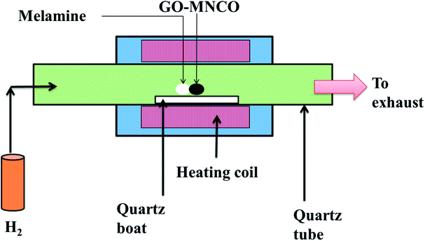
GO was synthesized from natural graphite (300 mm, MACKLIN Graphite) by a modified Hummers method.25 As-synthesized GO (30 mg) was dispersed in deionized (DI) water (60 mL) and ethanol solution (60 mL) by ultrasound for 30 min to create a brown dispersion solution (0.5 mg mL−1). CoCl2·6H2O (120 mg), Mn(CH3COO)2·4H2O (240 mg), Ni(NO3)2·6H2O (150 mg) and hexamethylenetetramine (HMT, 210 mg) were added to the above suspension. After ultrasonic treatment for another 10 min, the mixed solution was heated to 90 °C in an oil bath under constant stirring for 10 h.26 At the end of 10 h, the black product was filtered and the sample was dried overnight at 60 °C. After complete desiccation occurred, the samples were ground to fine powders.10 mg of the precursor GO–MNCO and 400 mg of the melamine powder were mixed together, and placed in horizontal quartz CVD reactor (Fig. 1), and heated to 800 °C at 20 °C min−1 in H2 (99.999%) atmosphere with a flow rate of 70 sccm for 30 min. At the end of this 30 min, the system was allowed to cool to room temperature in H2 atmosphere at a flow rate of 30 sccm.
2.2 Material characterizations
The morphologies and nano-structure of as-prepared samples were characterized by field-emission scanning electron microscopy (SEM, FEI QUANTA 200F) and transmission electron microscopy (TEM, JEOL 2010F). The X-ray diffraction (XRD, PANalytical) was carried out to determine elemental composition. The structures of the samples were investigated by X-ray photoelectron spectroscopy (XPS, PHI-5700) and Raman spectroscopy (Raman, Horiba Evolution). The pore structures of the samples were characterized using nitrogen adsorption and desorption isotherms by a Quanta Chrome adsorption instrument (ASAP 2020).3. Results and discussion
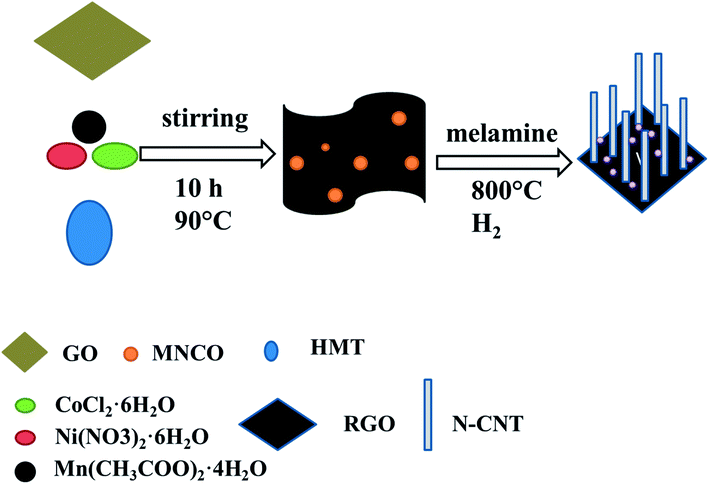
A scheme showing the synthesis of NCNT/G via a two-step procedure is illustrated in Fig. 2. First, GO is mixed with metal salts including Mn, Ni, Co, and hexamethylenetetramine (HMT) by heating and stirring. The metal ions of Mn2+, Ni2+, Co2+ bind strongly with functional groups on the GO surface, forming GO decorated with MNCO. Next, the GO–MNCO and melamine powder are transferred to the quartz boat and heated under the H2 atmosphere at 800 °C. During this process, the GO is converted to reduced graphene oxide (RGO). At the same time, the metal oxides are also reduced to metal nanocatalysts Ni–Co and the melamine is pyrolyzed to provide carbon and nitrogen atoms and eventually forms nitrogen-doped CNTs.27,28SEM
The SEM image (Fig. 3(a)) of the GO–MNCO composite shows a nanoflake morphology characterized by thin and uniform sheets. In this architecture, each nanoflake is connected with the others, thus forming a porous 3D structure.29 The unique structure facilitates the growth of dense carbon nanotubes. To demonstrate the function of melamine, two control experiments are done. As shown in Fig. 3(b), no CNTs but only RGO sheets are obtained when melamine is absent in this fabrication. We can clearly observe numerous white spots on the RGO sheets, which are Ni–Co nanocrystals. These results indicate that the GO–MNCO composite is reduced to Ni–Co nanocatalysts dispersed on an RGO surface (RGO–MNC) under the H2 atmosphere. The RGO does not function as a carbon source to support the growth of CNTs. HRTEM images show flake structure and the number of layers of RGO in Fig. 3(c) and (d). A typical crumpled surface is clearly observed, indicating the features of the 2D structure. These catalysts anchored on the RGO surface offer more initial points for CNT growth when a carbon source is added.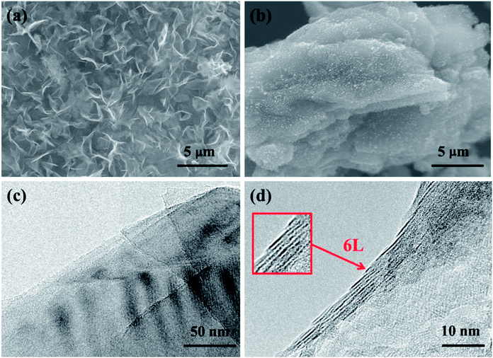 | ||
| Fig. 3 (a and b) The SEM images of GO–MNCO and RGO, respectively. (c and d) HRTEM images of the RGO and the number of layers are shown in the box in (d). | ||
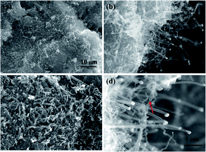
Fig. 4 shows the SEM images of the RGO–MNC surface that results when a carbon source such as melamine is added to the reaction mix. CNTs are distributed uniformly and densely on the RGO surface as shown in Fig. 4(a) and (c). The magnified views (Fig. 4(b) and (d)) reveal that the CNTs are vertically aligned and there are some white dots on the tip of CNTs, which are confirmed by TEM to be metal catalyst (as shown in Fig. 5(a) and (b)). This probably corresponds to the typical tip growth model based on the vapor–liquid–solid mechanism. In this model, hydrocarbons are decomposed to gaseous carbon fragments and then diffuse to the surface of metal to promote the growth of CNTs.30 The SEM images also clearly display bead-like CNTs as shown by red arrows in Fig. 4(d).
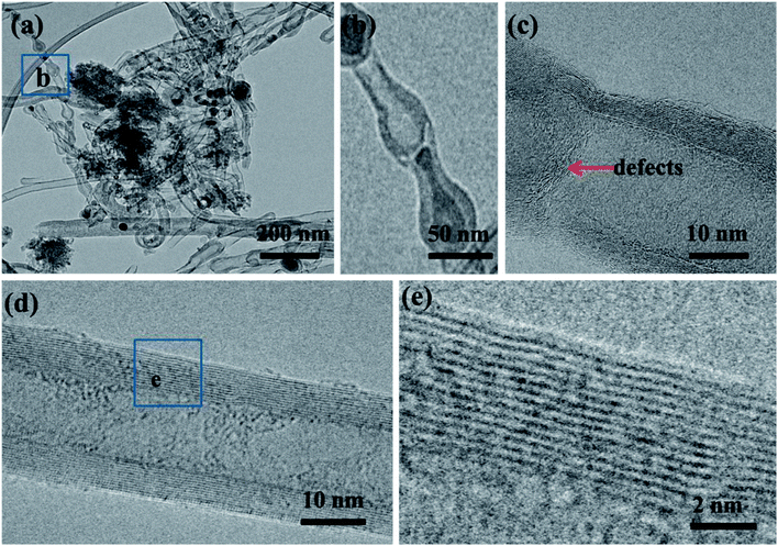
TEM
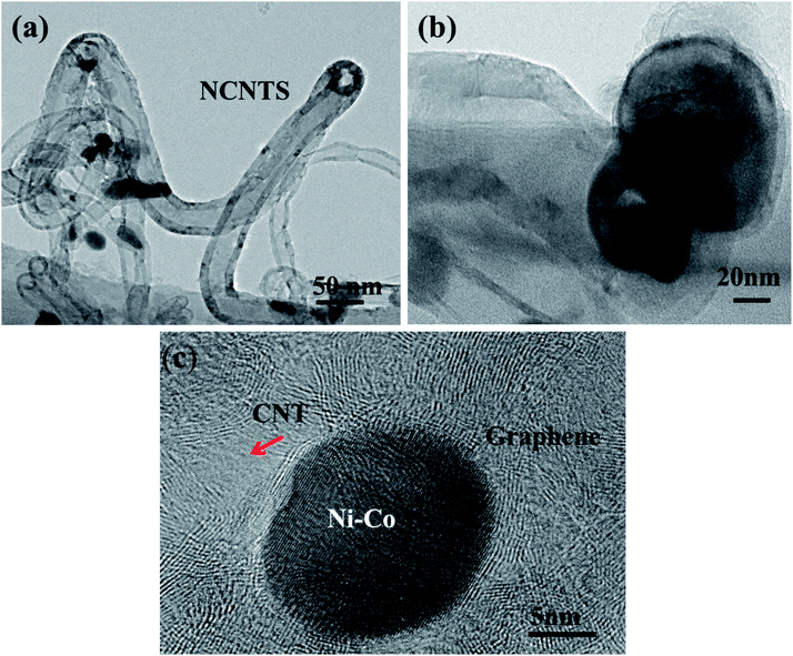
To further confirm the growth mode, TEM and HRTEM have been used to further probe the nanostructures. As shown in Fig. 5(a), the catalysts are located on the tip of the CNTs, which is consistent with the tip growth mode. From Fig. 5(b) the diameter of the metal catalysts and CNTs are determined to be between 100–150 nm and 9–12 nm, respectively. In addition, the obtained materials are mainly multi-walled CNTs. HRTEM image (Fig. 5(c)) shows the interface between CNTs and graphene layers. The carbon nanotube root (red arrow in Fig. 5(c)) connects to the RGO sheets. Interconnected CNTs and RGO facilitate electron transport and prevent the stacking and aggregation of graphene sheets.31Due to the incorporation of nitrogen atom into CNTs, we can observe a bead-like CNTs structure (Fig. 6(a)), which is similar to the reported bamboo-like CNT structures.15 HRTEM image (Fig. 6(b)) shows that the bead-like CNTs are multi-walled. There are many wrinkles on the walls of CNT and highly defective sites at the node as shown in Fig. 6(c). This wrinkled morphology is known to originate from the substitution of nitrogen atoms in the graphitic domain, which would increase active sites of the material.23 These defective sites can enhance electron transport capacity or catalytic activity.23 The HRTEM images in Fig. 6(d) and (e) further illustrate a typical morphology of multiwall CNTs with an inside diameter of about 9 nm and a wall thickness of 4 nm. To demonstrate the composition of the materials, the structures of the RGO and NCNT-G hybrid are studied by X-ray diffraction (XRD) as shown in Fig. 7(a). The characteristic peak of these two samples are identified at 26.2°, corresponding to the (002) plane of graphite carbon, and the strong peak at 44.5° is due to the presence of catalyst particles, nickel and cobalt.11,19 The peaks at 52.5° and 76° refer to ternary metal mixtures. Noticeably, the characteristic peak of NCNT/G is corresponding with RGO and the characteristic peak of NCNT/G is sharper than that of RGO, revealing that the graphitic degree increases due to the presence of CNTs.23 The change in the structure caused by the CNT intercalation is further studied by Raman spectroscopy. As shown in Fig. 7(b), the intensity of D and G bands are 1340 and 1580 cm−1, respectively. The intensity ratio (ID/IG) of NCNT/G is about 0.8 and is smaller than RGO (0.9), confirming that N-doped CNT is beneficial to improve graphitic crystalline structure duo to the presence of high-level defects.31
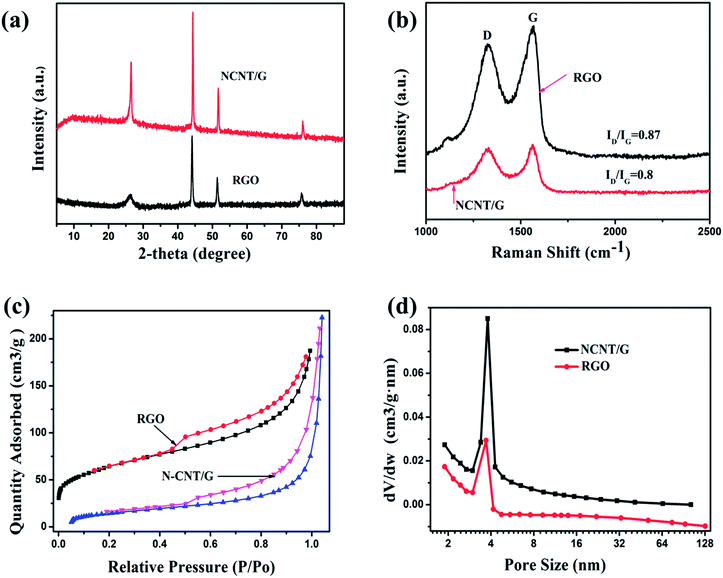 | ||
| Fig. 7 (a) XRD patterns of NCNT/G and RGO. (b) Raman spectra of NCNT/G and RGO. N2 gas adsorption–desorption curves (c) and pore distribution (d) of NCNT/G and RGO. | ||
In addition, we carried out the Brunauer–Emmett–Teller (BET) measurements to quantitatively analyze the porosity characteristics of the two samples. Nitrogen adsorption–desorption isotherms of NCNT/G and RGO (Fig. 7(c)) show a type-IV isotherm curve, indicating the presence of mesopores24 and further can be confirmed by the pore size distribution derived from the N2 desorption peaks in Fig. 7(d), which shows that most of the pores are small mesopores (∼5 nm). The surface area of NCNT/G is 226 m2 g−1 and the pore volume is 0.25 cm3 g−1, which are higher than the surface area (58 m2 g−1) and the pore volume (0.21 cm3 g−1) of the RGO. The increase of surface area and pore volume are caused by the addition of N-doped CNTs that can effectively integrate with graphene nanosheets to form the 3D hierarchical structure.
X-ray photoelectron spectroscopy (XPS) further confirms that the as-prepared carbon structure contains nitrogen. The XPS survey spectrum (Fig. 8(a)) shows the dominant C 1s peak at 284.0 eV, N 1s peak at 397.9 eV, and O 1s peak at 531.2 eV, respectively. High-resolution XPS N 1s spectra for NCNT/G reveal the assignments of three types of nitrogen defects, corresponding to pyridinic-N (397.98 eV), pyrrolic-N (400.25 eV), graphitic-N (401.16 eV), respectively, as demonstrated by Fig. 8(b). The graphitic-N indicates that nitrogen atoms have been successfully doped into the carbon structure.
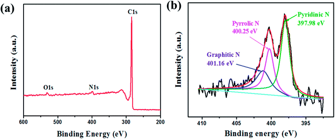 | ||
| Fig. 8 (a) XPS survey spectrum of NCNT/G and RGO. (b) High-resolution XPS spectra of N 1s for NCNT/G and RGO. | ||
4. Conclusions
In summary, a direct pyrolysis of N-rich melamine by CVD technique has been demonstrated to synthesize 3D bead-like N-doped CNT/graphene structures. It is the first time that low-cost raw melamine has been used as both a carbon and nitrogen source simultaneously. The as-prepared N-CNT/G hybrids are built from N-doped CNTs and few-layers reduced graphene oxide. Meanwhile, the bead-like CNTs are observed in the hybrid structure, which is due to the doping of nitrogen into carbon atom network. The modulation of the carbon surface caused by nitrogen can introduce more defects and active sites in the carbon framework, thus improving the electronic conductivity and surface wettability. This is beneficial to improve electrochemical properties and chemical adsorption ability. As a result, the NCNT/G hybrids are expected to be a promising host for many energy-storage and energy-conversion materials, such as supercapacitor, Li-ion secondary batteries and Li–S batteries. Moreover, this simple route is versatile and scalable, and can be a strategy for fabricating other 3D N-doped carbonaceous nanostructures.Conflicts of interest
There are no conflicts to declare.Acknowledgements
G.-P. D acknowledges the National Natural Science Foundation of China (Grants 51462022 and 51762032) and the Natural Science Foundation Major Project of Jiangxi Province of China (Grant 20152ACB20012) for financial support of this research. K. V and M. H. W acknowledge the support of NSF CREST Award HRD-0833184 and the NSF PREM Award DMR 1523617. The assistance of Dr Zhi-Qun Tian at Guangxi University (HRTEM measurements) and Dr A. S. Kumbhar (SEM and HRTEM measurements), CHANL at UNC Chapel Hill, is also greatly appreciated.References
- C. Lee, X. Wei, J. W. Kysar and J. Hone, Science, 2008, 321, 385–388 CrossRef CAS PubMed.
- L. Bing, X. Cao, O. H. Guan, C. J. Wei, X. Zhou, Z. Yin, L. Hai, J. Wang, B. Freddy and H. Wei, Adv. Mater., 2010, 22, 3058–3061 CrossRef PubMed.
- S. Fan, M. G. Chapline, N. R. Franklin, T. W. Tombler, A. M. Cassell and H. Dai, Science, 1999, 283, 512–514 CrossRef CAS.
- J. S. Bunch, V. D. Z. Am, S. S. Verbridge, I. W. Frank, D. M. Tanenbaum, J. M. Parpia, H. G. Craighead and P. L. Mceuen, Science, 2007, 315, 490–493 CrossRef CAS PubMed.
- S. Stankovich, D. A. Dikin, G. H. B. Dommett, K. M. Kohlhaas, E. J. Zimney, E. A. Stach, R. D. Piner, S. T. Nguyen and R. S. Ruoff, Nature, 2006, 442, 282–286 CrossRef CAS PubMed.
- K. S. Novoselov, A. K. Geim, S. V. Morozov, D. Jiang, Y. Zhang, S. Dubonos, I. Grigorieva and A. Firsov, Science, 2004, 306, 666–669 CrossRef CAS PubMed.
- Z. Tang, S. Shen, J. Zhuang and X. Wang, Angew. Chem., 2010, 49, 4603–4607 CrossRef CAS PubMed.
- Z. Yan, L. Ma, Y. Zhu, I. Lahiri, M. G. Hahm, Z. Liu, S. Yang, C. Xiang, W. Lu and Z. Peng, ACS Nano, 2013, 7, 58–64 CrossRef CAS PubMed.
- J. Pang, A. Bachmatiuk, I. Ibrahim, L. Fu, D. Placha, G. S. Martynkova, B. Trzebicka, T. Gemming, J. Eckert and M. H. Rümmeli, J. Mater. Sci., 2016, 51, 640–667 CrossRef CAS.
- Y. S. Kim, K. Kumar, F. T. Fisher and E. H. Yang, Nanotechnology, 2012, 23, 15301–15307 CrossRef PubMed.
- F. Du, D. Yu, L. Dai, S. Ganguli, V. Varshney and A. K. Roy, Chem. Mater., 2011, 23, 4810–4816 CrossRef CAS.
- X. H. Xia, D. L. Chao, Y. Q. Zhang, Z. X. Shen and H. J. Fan, Nano Today, 2014, 9, 785–807 CrossRef CAS.
- X. R. Wang, X. L. Li, L. Zhang, Y. Yoon, P. K. Weber, H. L. Wang, J. Guo and H. Dai, Science, 2009, 324, 768–771 CrossRef CAS PubMed.
- H. Ma, J. He, D. B. Xiong, J. Wu, Q. Li, V. Dravid and Y. Zhao, ACS Appl. Mater. Interfaces, 2016, 8, 1992–2016 CAS.
- Y. L. Ding, P. Kopold, K. Hahn, P. A. van Aken, J. Maier and Y. Yu, Adv. Funct. Mater., 2016, 26, 1112–1119 CrossRef CAS.
- Y. M. Tan, C. F. Xu, G. G. Chen, Z. H. Liu, M. Ma, Q. J. Xie, N. F. Zheng and S. Z. Yao, ACS Appl. Mater. Interfaces, 2013, 5, 2241–2248 CAS.
- A. Dichiara, J. K. Yuan, S. H. Yao, A. Sylvestre and J. Bai, J. Nanosci. Nanotechnol., 2012, 12, 6935–6940 CrossRef CAS PubMed.
- J. X. Song, Z. Yu, M. L. Gordin and D. H. Wang, Nano Lett., 2016, 16, 864–870 CrossRef CAS PubMed.
- Z. J. Fan, J. Yan, L. J. Zhi, Q. Zhang, T. Wei, J. Feng, M. L. Zhang, W. Z. Qian and F. Wei, Adv. Mater., 2010, 22, 3723–3728 CrossRef CAS PubMed.
- W. H. Lee and J. H. Moon, ACS Appl. Mater. Interfaces, 2014, 6, 13968–13976 CAS.
- Z. Q. Xie, Z. Y. He, X. H. Feng, W. W. Xu, X. D. Cui, J. H. Zhang, C. Yan, M. A. Carreon, Z. Liu and Y. Wang, ACS Appl. Mater. Interfaces, 2016, 8, 10324–10333 CAS.
- D. W. Su, M. Cortie and G. X. Wang, Adv. Energy Mater., 2016, 7, 16023–16034 Search PubMed.
- J. J. Cai, C. Wu, S. R. Yang, Y. Zhu, P. K. Shen and K. L. Zhang, ACS Appl. Mater. Interfaces, 2017, 9, 33876–33886 CAS.
- H. L. Wu, L. Xia, J. Ren, Q. J. Zheng, C. G. Xu and D. M. Lin, J. Mater. Chem. A, 2017, 5, 20458–20472 CAS.
- W. S. Hummers Jr and R. E. Offeman, J. Am. Chem. Soc., 1958, 80, 1339 CrossRef.
- C. Wu, J. J. Cai, Y. Zhu and K. L. Zhang, ACS Appl. Mater. Interfaces, 2017, 9, 19114–19123 CAS.
- J. P. Paraknowitsch and A. Thomas, Energy Environ. Sci., 2013, 6, 2839–2855 CAS.
- Z. P. Chen, W. C. Ren, L. B. Gao, B. L. Liu, S. F. Pei and H. M. Cheng, Nat. Mater., 2011, 10, 424–428 CrossRef CAS PubMed.
- G. Y. Zhu, Z. He, J. Chen, J. Zhao, X. M. Feng, Y. W. Ma, Q. L. Fan, L. H. Wang and W. Huang, Nanoscale, 2014, 6, 1079–1085 RSC.
- A. C. Dupuis, Prog. Mater. Sci., 2005, 50, 929–961 CrossRef CAS.
- L. F. Chen, X. D. Zhang, H. W. Liang, M. G. Kong, Q. F. Guan, P. Chen, Z. Y. Wu and S. H. Yu, ACS Nano, 2012, 6, 7092–7120 CrossRef CAS PubMed.
| This journal is © The Royal Society of Chemistry 2018 |

