
 Open Access Article
 This Open Access Article is licensed under a
 Creative Commons Attribution 3.0 Unported Licence
Hierarchical CdMoO4 nanowire–graphene composite for photocatalytic hydrogen generation under natural sunlight†
Sunil R. Kadamab,
Rajendra P. Panmand b,
Shashikant Tekaleb,
Supriya Khoreb,
Chiaki Terashimac,
Suresh W. Gosavia,
Akira Fujishimac and
Bharat B. Kale*b
b,
Shashikant Tekaleb,
Supriya Khoreb,
Chiaki Terashimac,
Suresh W. Gosavia,
Akira Fujishimac and
Bharat B. Kale*b
aCentre for Advanced Studies in Materials Science, Department of Physics, Savitribai Phule Pune University, (Formerly University of Pune) Ganeshkhind, Pune-411007, India
bCentre for Materials for Electronics Technology (C-MET), Ministry of Electronics and Information Technology (MeitY), Government of India, Panchawati, Off. Pashan Road, Pune-411008, India. E-mail: bbkale@cmet.gov.in
cPhotocatalysis International Research Center, Research Institute for Science & Technology, Tokyo University of Science, 2641 Yamazaki, Noda, Chiba 278-8510, Japan
First published on 12th April 2018
Abstract
Herein, a facile in situ solvothermal technique for the synthesis of a CdMoO4/graphene composite photocatalyst is reported. Graphene oxide (GO) was synthesised by an improved Hummers' method and was further used for the in situ synthesis of graphene via GO reduction and the formation of a CdMoO4 nanowire/graphene composite. The structural phase formation of tetragonal CdMoO4 was confirmed from X-ray diffraction measurements. The small nanoparticle assembled nanowires, prismatic microsphere morphology and crystalline nature of the synthesized material were investigated using field emission scanning electron microscopy (FESEM) and transmission electron microscopy (TEM). Due to its unique morphology and stability, the CdMoO4/graphene composite was used as a photocatalyst for H2O splitting. In comparison to pristine CdMoO4, the CdMoO4/graphene composite showed the best hydrogen evolution rate, i.e. 3624 μmole h−1 g−1, with an apparent quantum yield of 30.5%. The CdMoO4/graphene composite has a higher photocatalytic activity due to the inhibition of charge carrier recombination. H2 production measurements showed that the ternary semiconductor/graphene composite has enhanced photocatalytic activity for H2 generation.
1. Introduction
Hydrogen has been considered as one of the best clean energy fuels owing to its green and renewable properties, compared with those of other fuels (such as methane, coal, gasoline, etc.), which could be used to power electronic devices, homes and automobiles.1,2 Conservative energy resources have been depleted to a large extent because of continuously rising energy demands.3 Therefore, it is essential to generate alternative eco-friendly and economically viable fuels, which can fulfil both current and future energy requirements. Hydrogen has been identified as a potential eco-friendly energy carrier in many low greenhouse gas energy scenarios.4 However, Arbuj et al. have previously discussed that only limited success has been achieved in the generation and storage of hydrogen.4 The different efficient ways to produce hydrogen, using, for example, photocatalytic, electrochemical and photoelectrochemical methods, have attracted much attention.1,5,6 Currently, coal gasification and the steam reformation of methane are the well-known and promising methods for high purity hydrogen production, but these are energy intensive processes and are undesirable in terms of the effect that they have on the environment.7,8 However, the technology to produce hydrogen in a cost-effective and eco-friendly way has not yet been developed. Considering the overall scenario and the abundant water supply on the Earth, hydrogen generation via photocatalytic water spitting is the most promising technique for renewable hydrogen production.9The first electrochemical generation of hydrogen catalyzed by a TiO2 photoanode with platinum as the counter electrode in saturated aqueous electrolyte was reported by Fujishima and Honda et al.10,11 In the literature, various semiconductor oxides such as TiO2,12,13 ZnO,5 SnO2/SnS2,14–16 WO3,17 Ga2O3,18 and ZnS,9 have been reported to be good photocatalysts for energy, as well as environmental related applications. However, most of these binary oxide photocatalysts have wide band gaps and show better activity in the presence of UV light, which only accounts for 5% of the solar spectrum, and do not show good photocatalytic activity in visible light.19 Furthermore, there have been attempts to develop anion doped TiO2,20,21 ZnO5 nanomaterials and Fe2O3,22 Bi2O3,23 BiVO4,17 MoO3,1 etc. as visible light active photocatalysts for H2 generation. However, the stability of these materials limits their commercial use as active photocatalysts. Hence, researchers have focused their attention on the development of stable and efficient ternary semiconductor photocatalysts for H2 production.24
Molybdenum based semiconductor catalysts have gained increasing attention because of their potential technological importance for a wide range of applications, such as photocatalytic hydrogen generation,25,26 environmental pollutant dye degradation,27,28 and in high density Li-ion batteries.29 In this context, we have attempted to develop the synthesis of ternary CdMoO4 via a simple solvothermal method. In the literature, there are some reports on the synthesis of CdMoO4,30–32 CdMoO4–graphene,33 Ag–CdMoO4 (ref. 34) and studies on their photocatalytic dye degradation, but there have been no reports on photocatalytic hydrogen generation using these materials. Enormous efforts have been made on the decoration of noble metals, such as Pt, on catalyst surfaces in order to increase the efficiency of photocatalysts. However, scaling up platinum-based catalysts is questionable due to the scarcity of Pt in the Earth's crust.35 Graphene is a well-known and significant material due to its two-dimensional layered sheet-like structure, which results in its remarkable properties. Graphene, in its composite form with semiconductor materials, has exhibited comparatively good photocatalytic activity over individual semiconductors due to its outstanding properties, such as high electron mobility, large surface area, excellent conductivity, stability and mechanical strength.36–38 In a graphene composite material, the 2D layered conjugated structure of graphene helps to reduce the electron and hole pair recombination time, which is beneficial for photocatalytic activity. During photocatalysis experiments, these carbon-related materials will act as both an electron-acceptor and an electron-transport material, facilitating the migration of photoinduced electrons and obstructing charge recombination to enhance the photocatalytic performance.39 To date, there have been reports on graphene and semiconductor oxide/sulfide composite photocatalysts, such as N–TiO2/graphene,40 CeMoO4,41 MoS2–graphene,42 BiFeO3–graphene,43 ZnO–graphene44 and Bi2WO6 (ref. 45) for energy and environmental related applications in the presence of UV/Visible light. Considering the significant characteristics of graphene, it is a potential support material for stabilizing the CdMoO4 photocatalyst, which enhances hydrogen generation by photocatalytic water splitting. The interfacial contact between the CdMoO4/graphene composite is responsible for its significant photocatalytic activity. The present study reports the in situ synthesis of the CdMoO4 nanostructure on few layered graphene via a solvothermal method. The structural and optical properties of the resulting CdMoO4/graphene composite materials have been thoroughly studied. The synthesized materials were used as photocatalysts for enhanced hydrogen generation via water splitting under solar light irradiation.
2. Experimental methods
2.1 Synthesis of graphene and its composites with CdMoO4 nanowires
All of the chemicals used for the synthesis of graphene oxide (GO) and CdMoO4 were analytical reagent grade and used without any further purification. The synthesis of GO was carried out using a previously reported improved Hummers' method.46 In the GO synthesis process, concentrated H2SO4 (69 ml) was added to a mixture of graphite flakes (3.0 g, 1 wt equiv.) containing NaNO3 (1.5 g, 0.5 wt equiv.), and the reaction mixture was cooled to 0 °C. Further to this, the addition of KMnO4 (9.0 g, 3 wt equiv.) was carried out by keeping the reaction temperature below 20 °C. The reaction mixture was warmed to 35 °C and allowed to stir for 30 min, followed by the slow addition of water (138 ml), producing a large exothermic increase in the reaction temperature to 98 °C. After that, external heating was introduced to maintain the reaction temperature at 98 °C for 15 min, then the heating was stopped, and the reaction was cooled in a water bath for 10 min. Additional water (420 ml) and 30% H2O2 (3 ml) were added, which produced another exothermic reaction, and the solution was then allowed to cool naturally. After natural cooling, the mixture was centrifuged (6000 rpm for 1 h), and the supernatant was decanted away. The obtained solid was dried overnight at room temperature, resulting in 1.2 g of solid product.The synthesized GO was used for the further synthesis of graphene/CdMoO4 nanowire composites. The detailed method for the synthesis of CdMoO4 nanowires and CdMoO4 prisms can be found in the ESI† (Experimental work A and B). As per the requirement, graphene oxide was put into a beaker containing methanol![[thin space (1/6-em)]](https://www.rsc.org/images/entities/char_2009.gif) :ethylene glycol in a ratio of 3:1, denoted as MEG (3:1), and kept in an ultrasonic bath for 15 minutes in order to separate the graphene layers. This solution was introduced into a reaction mixture of Cd and Mo precursors, and the resulting solution was transferred into a Teflon lined reactor, which was then packed into a stainless steel jacket, and kept in an oven at 150 °C for 24 hours. After completion of the reaction, the reactor was allowed to cool naturally. The product was filtered using Whatman filter paper no. 41. The product was dried at 80 °C for 4 hours in an oven. The collected powdered sample was further analyzed using various characterization techniques.
:ethylene glycol in a ratio of 3:1, denoted as MEG (3:1), and kept in an ultrasonic bath for 15 minutes in order to separate the graphene layers. This solution was introduced into a reaction mixture of Cd and Mo precursors, and the resulting solution was transferred into a Teflon lined reactor, which was then packed into a stainless steel jacket, and kept in an oven at 150 °C for 24 hours. After completion of the reaction, the reactor was allowed to cool naturally. The product was filtered using Whatman filter paper no. 41. The product was dried at 80 °C for 4 hours in an oven. The collected powdered sample was further analyzed using various characterization techniques.
2.2 Material characterization
The crystalline phases were investigated using powder X-ray diffraction (PXRD, XRD-D8, Advance, Bruker-AXS). The morphologies of the synthesized samples were investigated by field emission scanning electron microscopy (FESEM, Hitachi, S-4800). The optical properties of the powder samples were studied using a UV-visible-near infrared spectrometer (UV-VIS-NIR, PerkinElmer Lambda-950). For HRTEM (JEOL, 2010F instrument) studies, samples were prepared by dispersing the powder in ethanol, followed by ultrasonication in an ultrasonic bath for 5 min. The resulting dispersion was then drop-casted onto a carbon coated copper grid and was subsequently dried under vacuum. Room temperature Raman spectroscopy measurements were performed using a Renishaw InVia microscope Raman system with a laser wavelength of 532 nm in back scattering geometry laser power mode on a 5 mW sample with a laser spot size of 1 μm. The purity of the collected gas was analyzed by gas chromatography (Model Schimadzu GC-14B, MS-5 Å column, TCD, Ar carrier).2.3 Hydrogen generation via water splitting
Photocatalytic hydrogen (H2) generation via water splitting using CdMoO4 and its graphene composites as photocatalysts, in an aqueous solution containing methanol as a hole scavenger, was performed in an air tight quartz reactor (with a total reactor volume of 70 ml). The assembly was arranged on a terrace and the quartz reactor containing the reaction mixture was irradiated with solar light. The quartz reactor was equipped with a water circulator in order to absorb the IR radiation, which minimizes the effects of overheating. The intensity of the solar light was measured using a digital Lux meter. The observed average intensity of sunlight reaching the surface of the Earth is 125000 lux. Here, a known quantity (15 mg) of powder photocatalyst was suspended in a solution containing 20% (v/v) aqueous methanol. The total volume of the reaction mixture was 25 ml and there was 45 ml of free space in the reactor. The reactor was made air tight with a rubber septum and was sonicated for 5 min and then stirred for 30 min to homogenize the suspension. Finally, it was bubbled with ultra-high purity (UHP) nitrogen (N2) gas to remove all dissolved gases and purging was continued for 30 min to ensure and inert atmosphere in the reactor. After purging the gas, the flow of N2 was stopped and the reactor was made air tight. As soon as the reactor was irradiated with solar light, the photocatalytic splitting of water was initiated and the generated H2 gas was collected in the empty head space of the reactor. The amount and purity of the gas evolved was analyzed by gas chromatography (Model Schimadzu GC-14B, MS-5 Å column, TCD, and a porapak-Q packed column under N2 as the carrier gas). The apparent quantum efficiency (AQE) of the hydrogen generated was calculated using the following equation: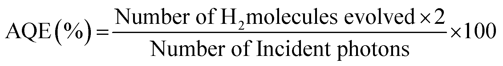
3. Results and discussion
The synthesized CdMoO4 in a methanol:ethylene glycol ratio of 3:1, denoted as MEG (3:1), and in a 1:1 ratio, denoted as MEG (1:1), and the 0.5%, 1%, 2% and 4% graphene composites synthesized using CdMoO4 in MEG (3:1) were characterized using PXRD, as shown in Fig. 1a and b. The PXRD patterns of CdMoO4 synthesized in MEG (3:1) and MEG (1:1) shown in Fig. 1a show a tetragonal phase formation. The diffraction peaks of CdMoO4 synthesized in both solvent systems could be well indexed and show body centred tetragonal phase formation, in good agreement with the reported JCPDS card no. 007-0209. The PXRD peak intensity of the CdMoO4 synthesized in MEG (3:1) was observed to be slightly higher than that of CdMoO4 synthesized in MEG (1:1). The peak intensity can be attributed to the crystalline nature and small particle size of the material. Along with the PXRD pattern of the CdMoO4 synthesized in MEG (3:1), the PXRD patterns of its 0.5%, 1%, 2% and 4% graphene composites are shown in Fig. 1b. The PXRD patterns clearly show that the intensity of the graphene peak at 2θ = 14.1 slightly increases upon an increase in the percentage of graphene. In Fig. 1b, in the graphene/CdMoO4 composite patterns, there are no extra peaks present, revealing the phase purity of the synthesized samples.
 | ||
| Fig. 1 (a) PXRD pattern of CdMoO4 synthesized in MEG solvent (3:1 and 1:1). (b) PXRD of the CdMoO4 composites synthesized in MEG solvent (3:1) with 0.5%, 1%, 2% and 4% graphene. | ||
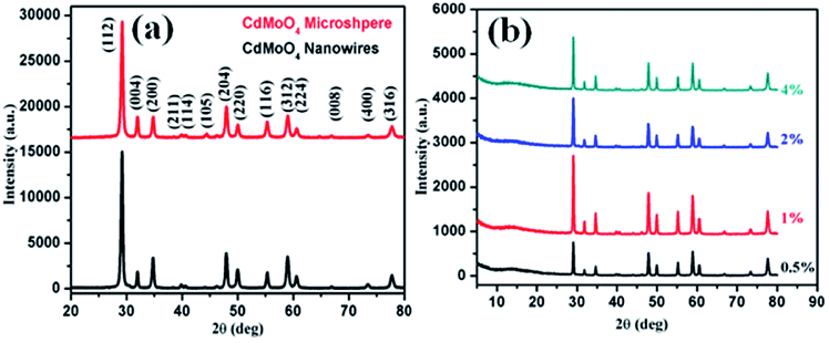
Morphological investigations on the as-synthesized CdMoO4 in the MEG (3:1) solvent system were performed using FESEM and the results are shown in Fig. 2a–d. From the FESEM images, the formation of a nanowire bundle-like morphology can be clearly observed. It is worth noting that a unique nanowire structure of CdMoO4 such as this has not been previously synthesized using a solvothermal process. The average size of the CdMoO4 nanowire bundles is observed to be 5 μm (Fig. 2a and b). Interestingly, the formation of the nanowire bundle-like structure was achieved through the assembly of nanowires, as observed in Fig. 2b. The average size of the individual nanoparticles was observed to be ∼30 nm in size (Fig. 2c and d). Overall, the FESEM observations show that there is a uniform distribution of the structural morphology.
 | ||
| Fig. 2 (a–d) FESEM images of as-synthesized CdMoO4 in the MEG (3:1) solvent system. | ||
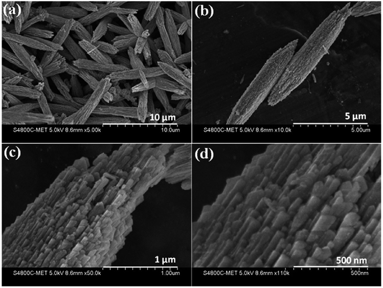
Further, a TEM investigation was performed in order to determine the morphology and crystalline nature of the CdMoO4 nanowires (Fig. 3a–d). A long nanowire bundle-like structure was noticed in the TEM images with an average size of 5 μm in length and 1.5 μm in thickness. It was observed that the corresponding nanowire formation takes place via the assembly of ordered uniform tiny nanoparticles of ∼20 nm in size (Fig. 3b), which is also in good agreement with the FESEM analysis. Fig. 3c shows the high-resolution (HR) TEM images taken from the edge of a nanoparticle, which provides more detailed structural information. The lattice spacings were observed to be 0.307 nm and 0.280 nm, which correspond to the (112) and (004) planes of tetragonal CdMoO4, respectively (Fig. 3c), and are also consistent with the results of the PXRD. Fig. 3d shows the selected area electron diffraction (SAED) pattern of the CdMoO4 sample, which clearly shows that it is crystalline in nature.
 | ||
| Fig. 3 (a and b) TEM images of as-synthesized CdMoO4 nanowires. (c) The high-resolution image, and (d) the SAED pattern. | ||
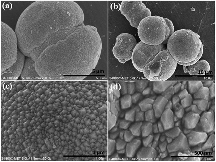
Morphological investigations on as-synthesized CdMoO4 synthesized in the MEG (1:1) system were carried out using FESEM and the results are shown in Fig. 4a–d. From the FESEM images, the formation of a microsphere (5–10 μm)-like morphology can be observed via the assembly of tiny close-packed nano prisms. It is also worth noting that such unique microspheres of CdMoO4 synthesized via a solvothermal process has not been previously observed. More significantly, the nanoparticles at the surface of the structure are prismatic in shape and the overall average size of the nano prisms is 50–100 nm (Fig. 4c and d). Overall, the FESEM observations show that there is a uniform distribution of the microsphere-like morphology.
 | ||
| Fig. 4 (a–d) FESEM images of as-synthesized CdMoO4 in the MEG (1:1) solvent system. | ||
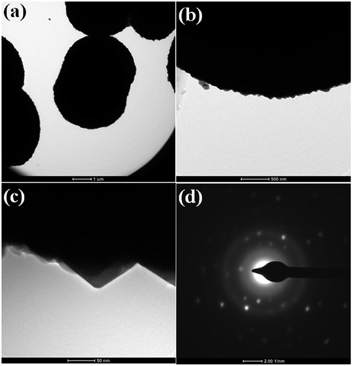
TEM investigations were performed in order to determine the morphology and crystalline nature of the CdMoO4 prismatic microsphere sample and the results are shown in Fig. 5a–d. The microspheres can be seen in the TEM image in Fig. 5a. The corresponding TEM images of the CdMoO4 microspheres show an ordered uniform structure. A nano prism is observed at the edge of a CdMoO4 microsphere, which clearly reveals that the microspheres are composed of nano prisms (Fig. 5b and c). The measured size of the prism is 50–100 nm (Fig. 5c), which is also in good agreement with the results from the FESEM analysis. Fig. 5d shows the selected area electron diffraction (SAED) pattern of the CdMoO4 sample, which clearly shows the crystalline nature of the sample.
 | ||
| Fig. 5 (a and b) TEM images of as synthesized CdMoO4 microsphere (c) high resolution image (d) SAED. | ||
GO nanosheets were synthesized using an improved Hummers' method. The structural phase formation of the as-prepared GO was investigated using powder X-ray diffraction (PXRD) and the powder pattern is shown in Fig. 6a. Fig. 6a shows an intense peak at 2θ = 10.8° and small peaks at 2θ = 21.8° and 42.3°, which indicates the phase formation of GO and is in good agreement with the data in the literature.
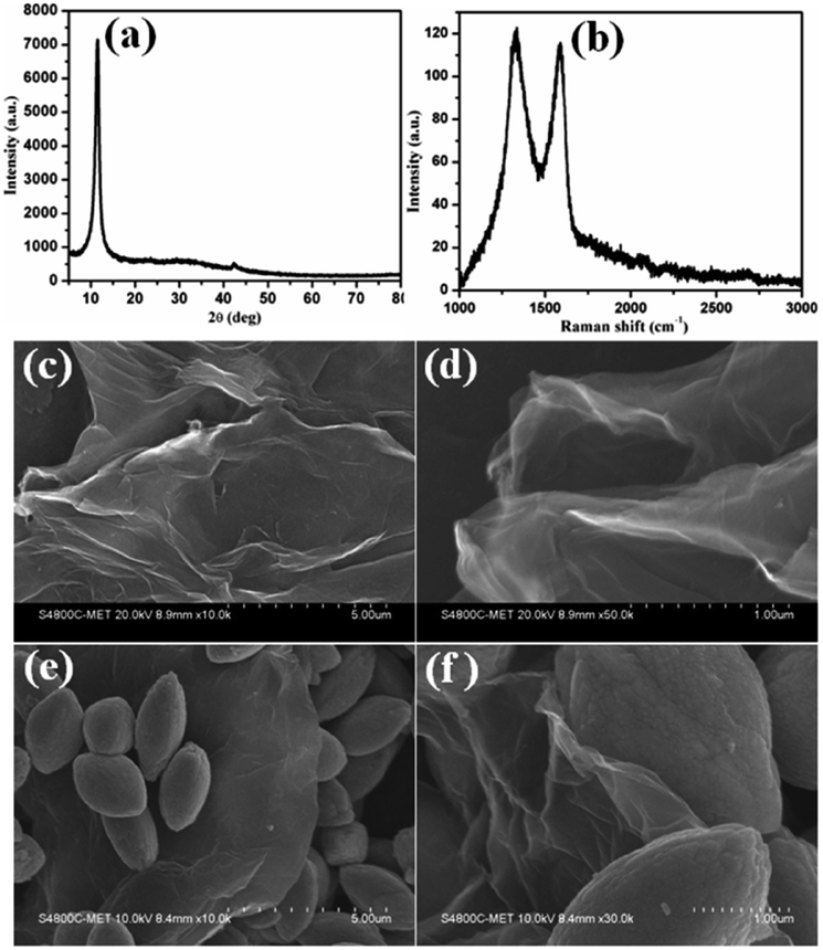 | ||
| Fig. 6 (a) The PXRD pattern of as-synthesized graphene oxide, (b) the Raman spectrum of graphene oxide, (c and d) FESEM images of graphene oxide and (e and f) FESEM images of the CdMoO4 nanowire/graphene composite materials. | ||
Raman spectroscopy is a very precise technique that is used to investigate the number of layers present in materials, so it was used to characterize the as-synthesized GO sample and the results are shown in Fig. 6b. The Raman spectrum of GO shows a D band at 1335 cm−1 and a broad G band at 1590 cm−1, assigned to the first-order scattering of the E2g mode. The prominent D band peak is due to structural defects created by hydroxyl and epoxide functional groups on the carbon basal plane. The surface morphology of the GO layered sheets was investigated using FESEM and the results are shown in Fig. 6c and d. The results confirm the formation of curved sheets of GO with a smooth surface, of various sizes (Fig. 6c and d). The thickness of the observed sheets is approximately ∼5 nm. Fig. 6e and f shows the FESEM images of the CdMoO4 nanowire/graphene composite materials. It shows the presence of sheets of graphene decorated with CdMoO4 nanowire bundles (5–7 μm size). It can be clearly observed that the nanowire CdMoO4 bundles are well dispersed over the multi-layer graphene sheets and remain firmly adhered to them, as is shown in Fig. 6(e and f). This intimate interaction is important for facilitating the transfer of photogenerated electrons from the CdMoO4 nanowire bundles to the graphene sheets during the photoexcitation process, which minimises the recombination of electrons (e−) and holes (h+). The presence of the CdMoO4 nanowire bundles anchored on the surface of the graphene sheets results in a larger surface area for moving electrons and holes and makes the material available for photocatalytic activity for a longer time period. This results in more active adsorption sites and photocatalytic reaction centres becoming available, therefore resulting in an enhanced photocatalytic activity.
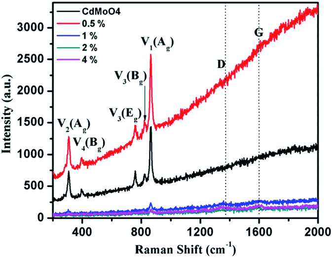
The solvothermally synthesized CdMoO4 nanowires and their 0.5, 1, 2 and 4 weight% graphene composites were further analyzed using Raman spectroscopy and the results are shown in Fig. 7a and b. The Raman spectra of CdMoO4 and its graphene composites show a peak at 866.1 cm−1, assigned as the ν1(Ag) symmetric stretching vibration mode of the [MoO4] cluster in the CdMoO4 structure. The Raman peaks at 820 and 760.5 cm−1 can be assigned to the significant anti-symmetric stretching ν3(Bg) and ν3(Eg) vibration modes of the CdMoO4 structure, respectively. Furthermore, the peaks at 397 and 306 cm−1 were assigned to the weaker ν4(Bg) and stronger ν2(Ag) modes of the [MoO4] tetrahedrons. A significant D band peak of graphene at 1358 cm−1 and a G band peak at 1593 cm−1 indicates the presence of layered structured graphene in the composite material. With an increase in the concentration of graphene in the CdMoO4 nanowire composites, the Raman peak intensity of the CdMoO4 peaks slightly decreases, whereas the magnified D and G band spectra, as shown in Fig. S3 in the ESI,† confirm the presence of graphene in the CdMoO4 composite materials.
 | ||
| Fig. 7 Raman spectra of the as-synthesized CdMoO4 nanowires and their 0.5, 1, 2 and 4 weight% graphene composites. | ||
The optical properties of the synthesized CdMoO4 microspheres, CdMoO4 nanowires and CdMoO4 nanowire/graphene composites were further investigated using UV-Vis spectroscopy and the results are shown in Fig. 8a and b. It is observed that both the CdMoO4 microspheres and nanowires show an absorption edge cut off at ∼375 nm (3.31 eV), as shown in Fig. 8a. It can be clearly observed that the CdMoO4 nanowires show a slightly higher absorption than that of the CdMoO4 microspheres, which can be attributed to the crystalline nature of the CdMoO4 nanowires. In the case of the CdMoO4 nanowire composites with graphene, a slight red-shift in the UV-Visible absorption spectra is observed. The absorption edge cut off of the composite materials is observed to be ∼380 nm (3.2 eV) for the 0.5 and 1% graphene composite materials. With an increase in the graphene concentration (in the 2–4% samples), a shift in the absorption spectra towards a longer wavelength at 401 nm (3.1 eV) is observed. The corresponding band gap energy of the composite materials was calculated from the Tauc plot, as shown in Fig. S1 in the ESI.†
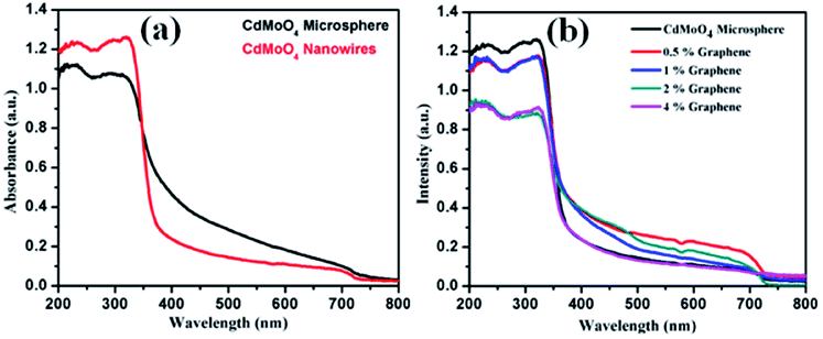 | ||
| Fig. 8 (a) UV-Visible absorption spectra of CdMoO4 nanowires and CdMoO4 microspheres and (b) UV-Visible absorption spectra of CdMoO4 nanowire composites with 0.5%, 1%, 2% and 4% graphene. | ||
The smaller size and crystalline nature of the CdMoO4 nanowires allows generated electrons and holes to move easily to the surface of the catalyst, making it available for photocatalytic activity, whereas in the case of the CdMoO4 microspheres, the generated electrons and holes cannot move easily to the surface of the catalyst due to the closely packed structure. It is proposed that in the graphene composites, the generated electrons and holes track into the layered graphene and move in the layered structure for a longer time, which reduces the electron and hole pair recombination and makes the material available for photocatalytic activity for a longer time period.
3.1 Photocatalytic investigations
The photocatalytic activity of the CdMoO4 microspheres, nanowires and the graphene composite materials were evaluated by measuring the amount of H2 generated via photocatalytic water splitting. The photocatalytic H2 generation activity of the synthesized materials was carried out in the presence of solar light. In the present study, methanol was used as a sacrificial reagent. F. Guzman et al. earlier discussed the use of methanol as a sacrificial reagent and its detailed mechanism.47 It seems that the presence of methanol decreases the e− and h+ pair recombination time. Methanol suppresses the evolution of oxygen through the formation of free radicals. As the reactor containing the photocatalyst is irradiated with solar light, the electrons in the conduction band (CB) and holes in the valence band (VB) are generated. The photogenerated holes (h+) in the VB oxidize the water molecules into H+ ions, while the electrons (e−) in the CB reduce the two H+ ions into one molecule of H2. The photocatalytic water splitting mechanism can be described as follows:| Semiconductor catalyst + hν → e−(CB) + h+(VB) |
| H2O + 2h+ → 1/2O2 +2H+ |
| 2H+ + 2e− → H2 |
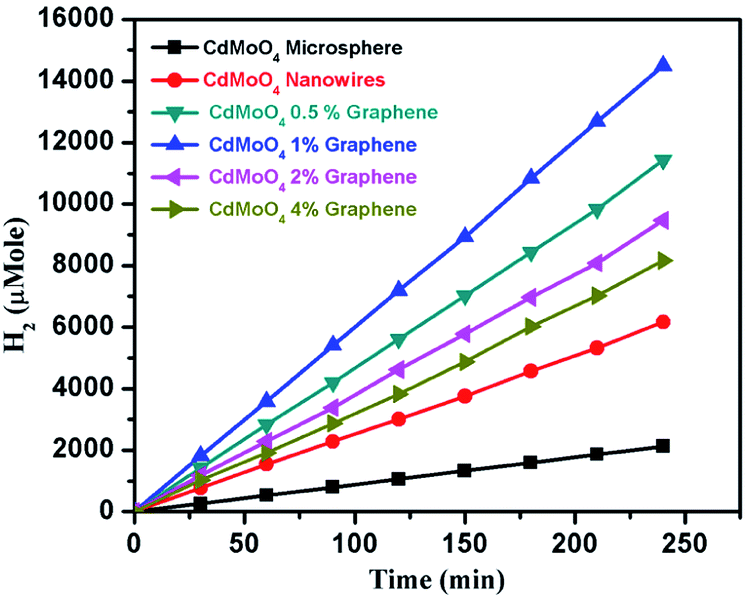
The results of the amount of H2 generated in μmole with respect to time for the CdMoO4 prismatic microspheres, nanowires and the graphene composites are shown in Fig. 9 and Table 1. 1540 and 531 μmole h−1 g−1 of H2 were generated for the CdMoO4 nanowires and prismatic microspheres, respectively. The linear plots of H2 generated in μmole vs. the time in minutes are shown in Fig. 9, revealing the continuous H2 generation from the water splitting over time. It was concluded that the higher photocatalytic activity observed for the CdMoO4 nanowires is due to the small size of the CdMoO4 particles, resulting in a greater surface area and increase in the number of active sites for photocatalytic activity. Slightly less hydrogen was generated by the CdMoO4 prismatic microspheres than that by the nanowires. The reason for the lower photocatalytic activity is that the nanoparticles in the CdMoO4 prismatic structure are agglomerated and closely packed, reducing the surface area and number of active sites, which restricts the easy movement of generated electrons and holes to the surface. It is well acknowledged that the surface morphology and size of the material plays a crucial and significant role in the context of photocatalytic H2 generation.3 The highest H2 generation of 3624 μmole h−1 g−1 was achieved for the 1% graphene–CdMoO4 nanowire composite. It was observed that the H2 generation activity increased for the 0.5 and 1% graphene CdMoO4 composites. Furthermore, the H2 generation activity was observed to decrease for the 2% and 4% graphene composites.
 | ||
| Fig. 9 Photocatalytic hydrogen generation activity plot with time for the CdMoO4 microspheres, nanowires and the 0.5, 1, 2 and 4 weight% graphene composites. | ||
| Sr. no. | Catalyst Name | Graphene (%) | H2 Production (in μMol h−1 g−1) |
|---|---|---|---|
| 1 | CdMoO4 microspheres | 0 | 531 |
| 2 | CdMoO4 nanowires | 0 | 1540 |
| 3 | CdMoO4 nanowires | 0.5 | 2856 |
| 4 | CdMoO4 nanowires | 1 | 3624 |
| 5 | CdMoO4 nanowires | 2 | 2368 |
| 6 | CdMoO4 nanowires | 4 | 2040 |
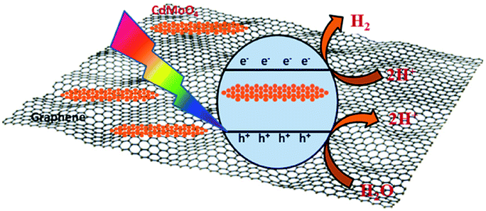
Interestingly, the 1% graphene/CdMoO4 nanowire composite shows almost double the hydrogen generation than that of the pristine CdMoO4 nanowires. It can be concluded that the highest photocatalytic H2 generation performance of the 1% graphene composite is due to the nanoparticles of the CdMoO4 nanowires and edge sites of the graphene and the vacancy defects in the structure. Graphene, in its composite form with semiconductor materials, has exhibited comparatively good photocatalytic activity compared with individual semiconductors due to its highly outstanding properties, such as high electron mobility, large surface area, excellent conductivity, stability and mechanical strength. The 2D layered conjugated structure of graphene in the composite helps to reduce the electron and hole pair recombination time, which is beneficial for the photocatalytic activity. During the photocatalysis experiments, the carbon-related material acted as both an electron-acceptor and electron-transport material; facilitating the migration of photoinduced electrons and obstructing the charge recombination, resulting in an enhanced photocatalytic performance. A schematic representation of the photocatalytic hydrogen generation catalyzed by the CdMoO4–graphene composite photocatalysts in natural sunlight is illustrated in Scheme 1.
 | ||
| Scheme 1 Schematic representation of the photocatalytic hydrogen generation mechanism of the CdMoO4–graphene composite photocatalysts. | ||
The small CdMoO4 particles facilitate the easy transport of the generated electrons and holes to the surface of the catalyst and track them into the graphene, which reduces the recombination time. Furthermore, there are more defects in the 1% graphene–CdMoO4 nanowire/graphene composite, which significantly suppress the recombination of photogenerated charge carriers. Considering the optical properties of the CdMoO4 and its graphene composite materials, the higher photocatalytic activity observed for the CdMoO4 nanowire/1% graphene composite is quite understandable. As the graphene% increases in the CdMoO4 nanowires, an increase in the absorption of visible light is observed. This enhanced absorbance leads to the formation of a large number of e− and h+ pairs, resulting in higher photocatalytic activity. In the present study, few layered graphene nanosheets with CdMoO4 nanowires were used, which have good stability along with a short carrier diffusion time and hence show good photocatalytic activity. A further increase in the graphene content (in the 2% and 4% graphene composites) led to a decrease in the observed H2 generation activity. It is quite reasonable that the introduction of a greater percentage of graphene led to a shielding of the active sites on the catalyst surface. This shielding effect, brought about by the presence of an excess amount of carbon based material in metal oxide catalyst materials has been discussed in detail by Yu et al.48 Optimized graphene content plays a significant role in attaining the highest photocatalytic activity in the graphene/CdMoO4 nanowire composites. In the present study, the highest photocatalytic activity obtained for the 1% graphene CdMoO4 nanowire composite is higher than that previously reported for a metal oxide/graphene composite material.40,49–51 Overall, the results show that the 1% graphene/CdMoO4 nanowire composite is an excellent stable photocatalyst for H2 generation in solar light.
This is the only report which reveals photocatalytic H2 production via H2O splitting under solar light catalyzed by a graphene/CdMoO4 nanowire composite. The stability of the catalyst was confirmed by performing repeatability studies, which showed that the catalyst retains its activity after being recycled five times, which shows the reproducibility of the results. The PXRD pattern of the reused catalyst sample did not show any change in the phase of the CdMoO4 nanowire/graphene composite catalyst, which clearly shows the stability of the catalyst. No H2 production was observed in the absence of a catalyst or under dark conditions (in the absence of light). Overall, it is concluded that the CdMoO4 nanowire/graphene composite catalyst is quite a stable and active photocatalyst for photocatalytic H2O splitting in solar light.
4. Conclusion
In conclusion, an in situ one step solvothermal approach has been demonstrated for the synthesis of CdMoO4 and its graphene composites. The syntheses of CdMoO4 nanowires and prismatic microspheres were demonstrated. CdMoO4 nanowire bundles were observed to uniformly decorate few layered graphene sheets. Photocatalytic H2 generation via water splitting in solar light was investigated for CdMoO4 and its graphene composites. The highest H2 generation of 3624 μmole h−1 g−1 achieved for the 1% graphene CdMoO4 nanowire composite, which has not previously been reported. The small particles, edge sites and defects of the graphene in the catalyst structures play an important key role in the enhancement of H2 generation. The generated electrons and holes easily transfer to the surface and quite easily track into the graphene due to the thinness of the graphene nanosheets, which inhibits charge recombination.Conflicts of interest
Author has no conflicts of interest.Acknowledgements
Dr Sunil Kadam would like to thank University Grants Commission for financial support towards the implementation of the project under D S Kothari Post doctoral fellowship scheme (grant no. F.42/2006(BSR)/CH/16-17/0066). Authors would like to thank Sakura Exchange Program in Science for allowing to visit Photocatalysis International Research Centre Research Institute for Science & Technology, Tokyo University of Science, Japan. Author also would like to thank for the C-MET, Pune for allowing access of all Experimental, Characterization and Photocatalytic water splitting facility. All research work is carried out at C-MET, Pune India.Notes and references
- Z. Luo, R. Miao, T. D. Huan, I. M. Mosa, A. S. Poyraz, W. Zhong, J. E. Cloud, D. A. Kriz, S. Thanneeru, J. He, Y. Zhang, R. Ramprasad and S. L. C. Suib, Adv. Energy Mater., 2016, 6, 1600528 CrossRef.
- S. S. Penner, Energy, 2006, 31, 33–43 CrossRef CAS.
- S. R. Kadam, D. J. Late, R. P. Panmand, M. V. Kulkarni, L. K. Nikam, S. W. Gosavi, C. J. Park and B. B. Kale, J. Mater. Chem. A, 2015, 3, 21233–21243 CAS.
- J. K. Vaishnav, S. S. Arbuj, S. B. Rane and D. P. Amalnerkar, RSC Adv., 2014, 4, 47637–47642 RSC.
- S. R. Kadam, V. R. Mate, R. P. Panmand, L. K. Nikam, M. V. Kulkarni, R. S. Sonawane and B. B. Kale, RSC Adv., 2014, 4, 60626–60635 RSC.
- S. N. Lou, J. Scott, A. Iwase, R. Amal and Y. H. Ng, J. Mater. Chem. A, 2016, 4, 6964–6971 CAS.
- J. A. Turner, Science, 2004, 305, 972–974 CrossRef CAS PubMed.
- W. Lubitz and W. Tumas, Chem. Rev., 2007, 107, 3900–3903 CrossRef CAS PubMed.
- S. K. Apte, S. N. Garaje, S. S. Arbuj, B. B. Kale, J. O. Baeg, U. P. Mulik, S. D. Naik, D. P. Amalnerkar and S. W. Gosavi, J. Mater. Chem., 2011, 21, 19241–19248 RSC.
- A. Fujishima and K. Honda, Nature, 1972, 238, 37–38 CrossRef CAS PubMed.
- K. Maeda and K. Domen, J. Phys. Chem. Lett., 2010, 1, 2655–2661 CrossRef CAS.
- J. J. M. Vequizo, H. Matsunaga, T. Ishiku, S. Kamimura, T. Ohno and A. Yamakata, ACS Catal., 2017, 7, 2644–2651 CrossRef CAS.
- M. V. Sheridan, D. J. Hill, B. D. Sherman, D. Wang, S. L. Marquard, K.-R. Wee, J. F. Cahoon and T. J. Meyer, Nano Lett., 2017, 17, 2440–2446 CrossRef CAS PubMed.
- A. Roy, S. Arbuj, Y. Waghadkar, M. Shinde, G. Umarji, S. Rane, K. Patil, S. Gosavi and R. Chauhan, J. Solid State Electrochem., 2017, 21, 9–17 CrossRef CAS.
- M. Niu, F. Huang, L. Cui, P. Huang, Y. Yu and Y. Wang, ACS Nano, 2010, 4, 681–688 CrossRef CAS PubMed.
- M. Pawar, S. Kadam and D. J. Late, ChemistrySelect, 2017, 2, 4068–4075 CrossRef CAS.
- J. H. Baek, B. J. Kim, G. S. Han, S. W. Hwang, D. R. Kim, I. S. Cho and H. S. Jung, ACS Appl. Mater. Interfaces, 2017, 9, 1479–1487 CAS.
- V. Ghodsi, S. Jin, J. C. Byers, Y. Pan and P. V. Radovanovic, J. Phys. Chem. C, 2017, 121, 9433–9441 CAS.
- S. R. Kadam, R. P. Panmand, R. S. Sonawane, S. W. Gosavi and B. B. Kale, RSC Adv., 2015, 5, 58485–58490 RSC.
- S. Na Phattalung, S. Limpijumnong and J. Yu, Appl. Catal., B, 2017, 200, 1–9 CrossRef CAS.
- S. K. Khore, N. V. Tellabati, S. K. Apte, S. D. Naik, P. Ojha, B. B. Kale and R. S. Sonawane, RSC Adv., 2017, 7, 33029–33042 RSC.
- J. Wang, J. L. Waters, P. Kung, S. M. Kim, J. T. Kelly, L. E. McNamara, N. I. Hammer, B. C. Pemberton, R. H. Schmehl, A. Gupta and S. Pan, ACS Appl. Mater. Interfaces, 2017, 9, 381–390 CAS.
- R. Sharma, M. Khanuja, S. N. Sharma and O. P. Sinha, Int. J. Hydrogen Energy, 2017, 42, 20638–20648 CrossRef CAS.
- B. B. Kale, J. O. Baeg, S. M. Lee, H. Chang, S. J. Moon and C. W. Lee, Adv. Funct. Mater., 2006, 16, 1349–1354 CrossRef CAS.
- Q. Xiang, J. Yu and M. Jaroniec, J. Am. Chem. Soc., 2012, 134, 6575–6578 CrossRef CAS PubMed.
- F. M. Pesci, M. S. Sokolikova, C. Grotta, P. C. Sherrell, F. Reale, K. Sharda, N. Ni, P. Palczynski and C. Mattevi, ACS Catal., 2017, 7, 4990–4998 CrossRef CAS.
- W. Zhao, W. Ma, C. Chen, J. Zhao and Z. Shuai, J. Am. Chem. Soc., 2004, 126, 4782–4783 CrossRef CAS PubMed.
- N. Bate, H. Shi, L. Chen, J. Wang, S. Xu, W. Chen, J. Li and E.-B. Wang, Chem.–Asian J., 2017, 12, 2597–2603 CrossRef CAS PubMed.
- Y. Shi, Y. Wang, J. I. Wong, A. Y. S. Tan, C.-L. Hsu, L.-J. Li, Y.-C. Lu and H. Y. Yang, Sci. Rep., 2013, 3, 2169 CrossRef PubMed.
- L. Zhou, W. Wang, H. Xu and S. Sun, Cryst. Growth Des., 2008, 8, 3595–3601 CAS.
- D. Li and Y. Zhu, CrystEngComm, 2012, 14, 1128–1134 RSC.
- L. Zhen, W. S. Wang, C. Y. Xu, W. Z. Shao, M. M. Ye and Z. L. Chen, Scr. Mater., 2008, 58, 461–464 CrossRef CAS.
- J. Xu, M. Wu, M. Chen and Z. Wang, Powder Technol., 2015, 281, 167–172 CrossRef CAS.
- R. Adhikari, S. Malla, G. Gyawali, T. Sekino and S. W. Lee, Mater. Res. Bull., 2013, 48, 3367–3373 CrossRef CAS.
- M. Nguyen, P. D. Tran, S. S. Pramana, R. L. Lee, S. K. Batabyal, N. Mathews, L. H. Wong and M. Graetzel, Nanoscale, 2013, 5, 1479–1482 RSC.
- R. K. Upadhyay, N. Soin and S. S. Roy, RSC Adv., 2014, 4, 3823–3851 RSC.
- J. D. Buron, F. Pizzocchero, P. U. Jepsen, D. H. Petersen, J. M. Caridad, B. S. Jessen, T. J. Booth and P. Bøggild, Sci. Rep., 2015, 5, 12305 CrossRef CAS PubMed.
- A. A. Balandin, S. Ghosh, W. Bao, I. Calizo, D. Teweldebrhan, F. Miao and C. N. Lau, Nano Lett., 2008, 8, 902–907 CrossRef CAS PubMed.
- J. Qin, X. Zhang, C. Yang, M. Cao, M. Ma and R. Liu, Appl. Surf. Sci., 2017, 392, 196–203 CrossRef CAS.
- A. P. Bhirud, S. D. Sathaye, R. P. Waichal, J. D. Ambekar, C.-J. Park and B. B. Kale, Nanoscale, 2015, 7, 5023–5034 RSC.
- R. Karthik, J. Vinoth Kumar, S.-M. Chen, C. Karuppiah, Y.-H. Cheng and V. Muthuraj, ACS Appl. Mater. Interfaces, 2017, 9, 6547–6559 CAS.
- D. P. Kumar, S. Hong, D. A. Reddy and T. K. Kim, Appl. Catal., B, 2017, 212, 7–14 CrossRef CAS.
- S. Fatima, S. I. Ali, M. Z. Iqbal and S. Rizwan, RSC Adv., 2017, 7, 35928–35937 RSC.
- M. Rostami, RSC Adv., 2017, 7, 43424–43431 RSC.
- H. Wang, Y. Liang, L. Liu, J. Hu and W. Cui, Appl. Surf. Sci., 2017, 392, 51–60 CrossRef CAS.
- D. C. Marcano, D. V. Kosynkin, J. M. Berlin, A. Sinitskii, Z. Sun, A. Slesarev, L. B. Alemany, W. Lu and J. M. Tour, ACS Nano, 2010, 4, 4806–4814 CrossRef CAS PubMed.
- F. Guzman, S. S. C. Chuang and C. Yang, Ind. Eng. Chem. Res., 2013, 52, 61–65 CrossRef CAS.
- J. Yu, T. Ma and S. Liu, Phys. Chem. Chem. Phys., 2011, 13, 3491–3501 RSC.
- J. Shen, M. Shi, B. Yan, H. Ma, N. Li and M. Ye, Nano Res., 2011, 4, 795 CrossRef CAS.
- N. Li, G. Liu, C. Zhen, F. Li, L. Zhang and H.-M. Cheng, Adv. Funct. Mater., 2011, 21, 1717–1722 CrossRef CAS.
- W. Fan, Q. Lai, Q. Zhang and Y. Wang, J. Phys. Chem. C, 2011, 115, 10694–10701 CAS.
Footnote |
| † Electronic supplementary information (ESI) available. See DOI: 10.1039/c8ra01557k |
| This journal is © The Royal Society of Chemistry 2018 |