 Open Access Article
Roll-to-roll continuous carbon nanotube sheets with high electrical conductivity
Songlin Zhang ab,
Branden E. Leonhardtac,
Nam Nguyenab,
Abiodun Oluwalowoab,
Claire Jolowskyab,
Ayou Haoab,
Richard Liangab and
Jin Gyu Park
 *ab
*ab
aHigh-Performance Materials Institute, Florida State University, 2005 Levy Ave., Tallahassee, FL 32310, USA
bDepartment of Industrial and Manufacturing Engineering, FAMU-FSU College of Engineering, 2525 Pottsdamer St., Tallahassee, FL 32310, USA
cDepartment of Chemical and Biomedical Engineering, FAMU-FSU College of Engineering, 2525 Pottsdamer St., Tallahassee, FL 32310, USA. E-mail: jgpark@fsu.edu
First published on 3rd April 2018
Abstract
Large scale manufacturing of electrically conductive carbon nanotube (CNT) sheets with production capability, low cost, and long-term electrical performance stability is still a challenge. A new method to fabricate highly conductive continuous buckypaper (CBP) with roll-to-roll production capability and relatively low cost is reported. The electrical conductivity of CBP can be improved to 7.6 × 10⁴ S m−1 by using an oxidant chemical (i.e. HNO3 and I2) doping method. To compensate for the conductivity degradation caused by the instability of the oxidant chemical doping, a polymer layer of poly(3,4-ethylenedioxythiophene)-poly(styrenesulfonate) (PEDOT:PSS) was coated on the chemically doped CBP. The fabricated highly conductive CBP showed stable electrical performance in air for more than a month. This CBP material with high electrical conductivity, relatively low cost, and roll-to-roll manufacturing capability could enable a wide range of engineering applications including flexible conductors, electromagnetic interference (EMI) shielding materials, and electrodes in energy devices.
Introduction
Since the discovery of carbon nanotubes (CNTs) in 1991 by Sumio Iijima,1 many scientists became interested in their high electrical conductivity and potential applications. With the electrical conductivity of an individual nanotube reaching up to 108 S m−1, CNTs are comparable to that of copper2 but with only 1/6 of its density. Even today, we have seen explorations of using CNT wires in transformer and motor demonstrations, and other electrical applications in an attempt to replace copper.3–5 However, the astounding electrical properties of individual CNTs begin to diminish upon the creation of macroscopic CNT assemblies such as films (or buckypaper) and fibers (or wires), due to aggregation of defects, intertube contact resistance, and the misalignment of CNTs.6–9 Reducing these negative effects is difficult due to the CNT's complicated synthesis conditions, hydrophobicity, large aspect ratio etc., making it problematic to create homogenous dispersions in which one can align or modify individual tubes using various methods.10–13 Fabricating CNT fibers with high conductivities has been studied extensively by many researchers due to the ease of effectively eliminating those drawbacks in fiber forms14–19 compared to CNT films.20–23 Different ways to spin CNT fibers include from solution,24 arrays,18 aerogels,8 and rolling CNT films.25 Following fiber spinning, certain post-treatment methods are available to further increase conductivity. For instance, Liu et al. began with aerogel spun CNT fiber and applied a nitric acid treatment yielding a conductivity up to 1.8 × 10⁶ S m−1.15 Other groups used mechanical densification to reduce fiber diameter size, thereby reducing intertubular space and reducing contact resistance between the tubes.8,16,26–28 Duong and co-workers reported the effectiveness of mechanical pressing to improve the conductivity to the range of 106 S m−1.15,16,27 However, translating these post-treatment processes to buckypaper is more complex due to the increased dimensions of buckypaper compared to the densely-packed, small-diameter fibers. It is challenging but highly demanding to fabricate highly conductive buckypaper for various commercial applications with the rise of portable flexible electronics such as roll-up cell phones and tablets. Using CNT thin films as conductive mediums within organic light-emitting diodes (OLEDs) has been a high possibility for this industry.29,30 Therefore, it is critical that these thin films exhibit high conductivity, while still retaining performance stability and should have the ability to be mass produced.The alignment of CNTs within a film was discovered to be an important factor for improving conductivity. Compared to the magnetic or electric field assisted method,10,31 mechanical stretching has been reported to be an effective way of aligning the CNTs in films at a reasonable cost, resulting in a relatively dense-packing structure with reduced internal contact resistance.32–34 But the resulting sample is usually small tapes due to the difficulty of balancing the product quality and scalability of handling large mechanical stretching machines. Meanwhile oxidant chemicals such as HNO3, H2SO4, and ICl etc., have been used on graphene oxide and CNTs as effective oxidizers, facilitating electron transport.35–39 For instance, iodine doping has been reported to be an effective dopant for facilitating high speed charge transfer between tubes, reaching a conductivity of 106 S m−1.24,40,41 There have been reports of chemical treatments on double-walled CNT (DWCNT) films with hydrogen peroxide where they obtained conductivities of ∼3.6 × 10⁵ S m−1 at 300 K.42 However, due to the highly reactive nature of oxidant chemicals, unstable electrical performance in open air is problematic. Furthermore, the capability of scalable production is a critical step for commercial applications. Currently, batch production of buckypaper has been reported extensively in literature, which falls into two basic categories: dry method and wet method. Directly spinning from CNT arrays which are first grown on a substrate is popular,43,44 but the quality variance from batch to batch is difficult to control and the production capability is limited due to the small size of substrates. Although continuous buckypaper (CBP) can be obtained using the floating catalyst chemical vapor deposition method (FCCVD),20 the controlled synthesis of buckypaper with good quality still needs further optimization. The wet method usually includes liquid casting and printing,45–47 droplet-drying,48 and vacuum filtration.49 Among them, vacuum filtration is a simple and versatile method suitable for nanoscale fibrous materials. Usually it involves a single stage vacuum filtration system using a CNT suspension.49 Even though large filtration system can be developed,50 the lateral dimension and length of fabricated buckypaper is still limited, which makes scalable roll-to-roll manufacturing of buckypaper production difficult.
In our previous study, it has been successfully demonstrated that the integration of I2 doping and CNT alignment achieves highly conductive CNT tapes with a stable electrical conductivity of 1.3 × 10⁶ S m−1.34 For this study, the main focus is placed on the large-scale production of buckypaper with desirable electrical conductivity and stable performance using a fast and low-cost method. Here we reported roll-to-roll CBP that could be fabricated in a short time by an in-house-built continuous filtration process machine.22 Utilizing our own CBP as a starting point, various post-treatments are investigated to improve its electrical conductivity, such as thermal treatment, nitric acid etching and oxidation, and gaseous iodine doping. The instability of the high conductivity after various post-treatments is also evaluated and is stabilized by using a polymer coating layer of poly(3,4-ethylenedioxythiophene)-poly(styrenesulfonate) (PEDOT:PSS). Most importantly, the continuous process with roll-to-roll manufacturing capability and low cost enables the CBP for large scale production, which is a critical key to its rapid development in engineering applications.
Experimental
Materials
Nitric acid (HNO3), iodine (I2), and poly(3,4-ethylenedioxythiophene)-poly(styrenesulfonate) (PEDOT:PSS) were purchased from Sigma-Aldrich Inc. (St Louis, MO). Multi-walled carbon nanotube (MWCNT) powder was purchased from General Nano Inc. (Cincinnati, OH). Surfactant of Triton™ X-100 was purchased from Alfa Aesar.Preparation of CBP
A homogeneous aqueous CNT suspension with surfactant was obtained with the assistance of a tip sonicator (QSonica S4000) for a specific sonication time. Using this CNT suspension, the CBP was fabricated at the High-Performance Materials Institute (HPMI) following the method described elsewhere.22,51 Briefly, the roll-to-roll manufacturing system was built, and comprised of a suspension tank of CNTs, and a filtration unit. The tank can continuously feed CNT suspension to the filtration unit, which is made of (i) a suspension chamber in fluid supplied from the suspension tank, (ii) a filter paper associated with two or more pinch rollers for continuous feeding, (iii) a filtration area associated with a vacuum pump, (iv) a drying area, and (v) a roll for collecting the CBP. The scalability of CBP roll-to-roll manufacturing makes it a promising raw material for a wide range of engineering applications. Raw CBP was used as prepared. The remaining surfactant was removed through a heat treatment in a box furnace at 400 °C for 3 hours with ambient atmosphere. These heated samples were directly used for the following chemical doping processes. Heat treated BP was soaked in 5 M HNO3 for 5 minutes. Then the samples were rinsed with de-ionized water and dried in an oven at 70 °C in air. After the acid treatment, additional iodine doping was conducted in a sealed glass container which housed iodine solid crystals and the HNO3 treated CBP together. The container was placed in an oven at 70 °C for two hours while the iodine sublimed and doped the sample.34 Also, exclusively iodine doped CBP after the heat treatment, following the same method above, was prepared as a control to investigate the synergistic effect of HNO3 and I2 on the electrical conductivity. The conductive polymer PEDOT:PSS was used as received without any dilution. It was coated on the surface of the doped CBP by a simple dip-coating method and dried at room temperature overnight. This simple and effective post-treatment, plus the roll-to-roll scalability of the CBP manufacturing could shed light on the capability of large-scale production and potentially broaden the applications of conductive CNT films.Characterizations
Electrical property measurements were conducted using a current source (Keithley 6221) and nanovoltmeter (Keithley 2182A) with the four-probe configuration stage (JANDEL Universal Probe). Resistivity (ρ) was calculated from the slope of the I–V curve based on the equation:where t is the sample thickness; V and I is the voltage and the current, respectively. Scanning electronic microscopy (SEM, JSM-7401F, JEOL.) was used for morphology analysis. Raman analysis was completed by a Renishaw inVia micro-Raman system using a 785 nm excitation wavelength. Thermogravimetric analysis (TGA) was conducted using the Q50 (TA Instrument Inc.) with a 10 °C min−1 rate from 50–850 °C in air and nitrogen.
Results and discussion
Fabrication of highly conductive CBP
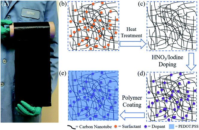
The CBP was fabricated by following the scale-up production method described in our previous work and patent.22,51 The roll-to-roll product from continuous process is as shown in Fig. 1a. Depending on the adjustable apparatus used in the continuous manufacturing process, CBP with a width of 6 or 12 inches was obtained. The post-treatments to improve the electrical conductivity of CBP is schematically depicted in Fig. 1b–e. Fig. 1b shows the raw CBP containing surfactant, which is insulating and detrimental to electron transfer. In this study, heat treatment was used to efficiently remove the remaining surfactant introduced in the CBP manufacturing process. A clean CBP could be obtained as shown in Fig. 1c, marked as heated CBP. To achieve even higher conductivity, chemical doping with nitric acid (HNO3) and iodine (I2) was performed and marked as HNO3 CBP, and I2 CBP, respectively. HNO3/I2 CBP represents the sample with the combination of HNO3 and I2 treatments. These dopants, as shown in Fig. 1d, could improve the electron transfer efficiency,52 resulting in a highly conductive CNT network. Lastly, a protective layer of conductive polymer (i.e. PEDOT:PSS) (Fig. 1e) was coated on the chemically doped CBP to stabilize the high electrical performance, which was pivotal in achieving long-term favorable electrical properties. The chemically doped CBP was characterized by Raman spectroscopy, SEM, and TGA. Also, the long-term stability of high conductivity was investigated by constantly checking the conductivity variance over time.Morphology characteristics of CBPs after different treatments
The scanning electron microscopic images of the CBP before and after heat treatment are shown in Fig. 2a and b. A homogeneous CNT bundle network of raw (Fig. 2a) and heated (Fig. 2b) CBP are observed. The randomly ordered CNT network and entanglement are preserved following the heat treatment. Under the heat treatment condition applied in this study (400 °C for 3 hours), the heated CBP should be free of surfactant due to the low decomposition temperature of Triton™ X-100 at 280–350 °C, and extended treatment time (3 hours). The resulting heated CBP still shows structural integrity (Fig. 2b), implying the success of heat treatment leading to surfactant removal without structural damages (more details of surfactant removal analysis will be discussed in the TGA data). Moreover, HNO3 and I2 doping did not deteriorate the CNT structure, as shown in Fig. 2c and d. The combination of HNO3 and I2 treatment was also demonstrated to show no negative effect on CNT structural integrity (Fig. 2e).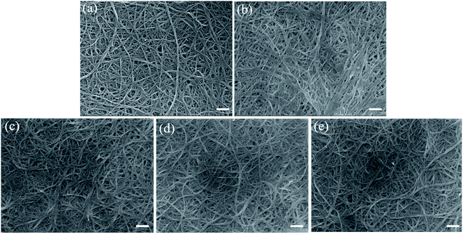 | ||
| Fig. 2 Surface morphology of CBP after different post-treatments from SEM images. (a) Raw CBP; (b) heated CBP; (c) HNO3 CBP; (d) I2 CBP; (e) HNO3/I2 CBP. Scale bar in each picture is 200 nm. | ||
Doping quality characterization
Raman spectroscopy is widely used to characterize the structure of CNTs in terms of the different bonding types of sp2 and sp3 hybridized carbon atoms. The D band (disorder-induced mode), which ordinarily shows the number of defects in CNTs,37 occurred at approximately 1308 cm−1 for raw CBP as marked in Fig. 3. Another characteristic peak is the G band, an intrinsic feature of all sp2 carbons,11 appeared at 1601 cm−1 for raw CBP. A powerful indicator to describe the electronic structure of different bonding types in CNTs after various post-treatments is the intensity ratio of ID/IG: a higher value implies that more defects are present in the CNTs. Fig. 3 shows the characteristic D and G bands for the raw CBP and its counterparts after various post-treatments. It is interesting to note that after various post-treatments, all D band positions remained similar to that of raw CBP, but ID/IG changed accordingly, as listed in Table 1. A potential explanation for why there is a slightly lower ID/IG ratio for heated CBP (1.22) as compared to that of raw CBP (1.26) may originate from the removal of surfactant, amorphous carbon and other impurities, which may serve as a defect source for the CNT network.37 After HNO3 treatment, potential oxygen-containing functional groups (structural defects) may be introduced to the side walls of CNTs,52 resulting in an increase of ID/IG from 1.22 to 1.41. Iodine is an oxidant chemical, but the ID/IG only increased to 1.27, much smaller than that of HNO3 treated CBP. It was reported that the iodine doping of CNTs is mainly through physical adsorption which does not create defects.53 But the slight increase of the ID/IG ratio could be ascribed to the possible presence of C–I bonding, which was also reported by Zhao et al.40 The combined treatment of HNO3 and I2 showed a reasonable value of ID/IG = 1.43.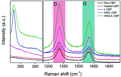 | ||
| Fig. 3 Raman spectroscopy of CBP after different post-treatments with D and G band marked as colored area. | ||
| Raw CBP | Heated CBP | HNO3 CBP | I2 CBP | HNO3/I2 CBP | |
|---|---|---|---|---|---|
| ID/IG | 1.26 | 1.22 | 1.41 | 1.27 | 1.43 |
Compared to the G band of raw and heated CBP, which is similar at 1601 cm−1, a red shift of 3 to 5 cm−1 was observed for the samples either doped by HNO3 (i.e. 1604 cm−1), I2 (i.e. 1605 cm−1), or the combination of both (i.e. 1606 cm−1). This shift was attributed to the charge transfer between CNT and dopant,37,41 with a larger shift implying a higher doping level. Another characteristic peak at around 155 cm−1 was observed for the samples doped by iodine and the combination of HNO3 and iodine, respectively, as shown in Fig. 3. This unique peak did not appear in other samples (i.e. raw CBP, heated CBP, or HNO3 doped CBP). This new peak could be explained by the iodine anion formation of triiodide (I−3) and/or pentaiodide (I−5).41,53
TGA results, as shown in Fig. 4, were also used to investigate the effect of surfactant removal by heat treatment and the dopant quantities of HNO3 and I2. The sample was heated up to 850 °C in air. The black line shows the TGA profile of raw CBP, which has two decomposition stages. The first decomposition stage with a weight loss of 42%, occurring at around 200–400 °C, mainly corresponded to the loss of surfactant of Triton™ X-100. The second decomposition stage occurred at approximately 550–680 °C, with a weight loss of around 51%, and was attributed to the decomposition of CNTs.34 These two decomposition stages showed two decomposition temperature peaks at 330 °C and 661 °C, which could be observed from the corresponding differential TGA curve. Obviously, only one decomposition peak (at around 644 °C) was observed in the TGA curves of heated CBP (green curve), indicating the effectiveness of heat-treatment induced surfactant removal. Similarly, the HNO3 treated CBP showed only a CNT decomposition stage. It is important to note that there is a slight difference in weight variance (i.e. 2–3%) in the temperature range of less than 600 °C between heated and HNO3 treated CBP, which may be explained by the loss of oxygen-containing functional groups induced by HNO3. The iodine doped CBP showed a new decomposition stage in addition to the CNT decomposition stage. The weight loss of 9.4% could be attributed the decomposition of iodine, which showed a decomposition temperature peak at 143 °C. No new peaks were observed for the combination of HNO3 and I2 doped sample.
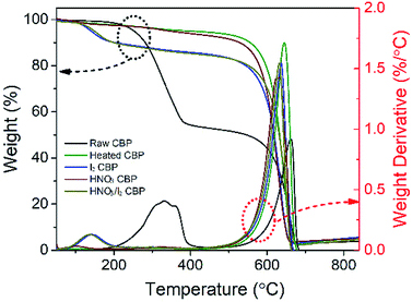 | ||
| Fig. 4 The TGA and the differential TGA curve of raw CBP and the samples after different post-treatments. The heating rate was 10 °C min−1 from 50–850 °C under air condition. | ||
Electrical performance improvement by chemical doping
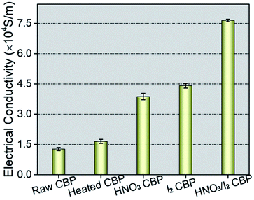
To understand the effect of surfactant removal and the dopant functionalization of HNO3 and I2, and the combination of them, the electrical properties of the samples were measured using a four-probe configuration. The measured electrical conductivity of the raw CBP was around 1.3 × 10⁴ S m−1, as seen in Fig. 5. After surfactant removal by heat treatment, the conductivity increased to approximately 1.6 × 10⁴ S m−1. Both HNO3 and I2 could significantly increase the conductivity to 3.8 × 10⁴ S m−1, and 4.4 × 10⁴ S m−1, respectively. Compared to HNO3 and I2 exclusively doped CBP cases, the effect of the combined HNO3 and I2 treatment on the electrical conductivity was more significant and the resulting conductivity increased up to 7.6 × 10⁴ S m−1, nearly 6 times higher than that of raw CBP.The mechanism of such a high improvement in electrical conductivity after HNO3 and I2 doping could directly result from the improved charge carrier concentration and its mobility.24,40 As oxidant chemicals, HNO3 or I2 showed the capability of withdrawing electrons from CNTs.41 Consequently, holes (electron deficiencies) could be created, which accelerate the neighboring hole mobility to reach an electronic equilibrium status.54 Based on the hole concentration and mobility, the electrical conductivity (σ) is defined by:
| σ = neμ |
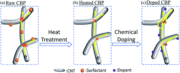
The electron transfer mechanism for raw CBP and the post-treated samples are schematically illustrated in Fig. 6. The surfactant (i.e. Triton™ X-100), either wrapping around the tubes or accumulating at the contact areas between tubes, could hinder the electron transport along tubes or across neighboring tubes (Fig. 6a) due to its non-conductive nature, resulting in a relatively high resistance (low conductance). Surfactant removal improved the efficiency of electron transfer between and along the tubes (Fig. 6b), which was verified by the minor improvement in the electrical conductivity (Fig. 5). When it comes to the further improvement in conductivity of the HNO3 and I2 treated CBP, fast hole mobility may be the explanation, which is also reported by others.38,39 These oxidant chemicals, acting as electron-withdrawing sites (electron acceptors), could create holes (p-type doping).39,55 Once the hole concentration increased (i.e. created by oxidant dopant of HNO3 and I2), a much higher electron transfer efficiency along tubes may be expected compared to raw CBP. Additionally, due to the possible electron conduction pathway established in the charge-transfer complex between neighboring tubes, an enhanced electron transfer across different tubes may also contribute to the improved electrical conductivity as shown in Fig. 6c.55
Improved stability of highly conductive CBP by PEDOT:PSS
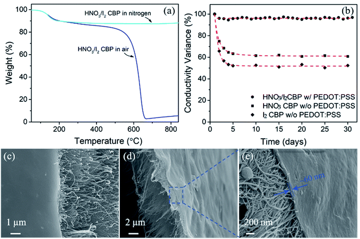
There is a major concern for CBP with high electrical conductivity in long-term performance stability. Although doping with HNO3 and I2 could achieve high electrical conductivity, other researchers also reported the instability of the doping effect.53,54 In this study, we first investigated the thermal stability of HNO3/I2 CBP. In Fig. 7a, the results of TGA data carried out in both an air and nitrogen atmosphere showed the same degradation peak at ∼143 °C, which was attributed to the loss of iodine. This is consistent with the common knowledge that iodine can sublime even at room temperature. In addition, in terms of electrical conductivity as shown in Fig. 7b, nearly a 40% and 50% decrease was observed from HNO3 and I2 doped CBP, respectively. It is critical to achieve long-term stability for potential engineering applications. In this study, the conductive polymer PEDOT:PSS was used as a protective coating layer to maintain the highly conductive performance of CBP doped by the combination of HNO3 and I2. After a simple dip-coating method, the PEDOT:PSS coated HNO3/I2 CBP was dried at room temperature. It is interesting to note that only a small conductivity variance (3–5%) appeared for a testing period of more than a month. After studying the surface morphology of the polymer coated CBP, as shown in Fig. 7c, it is possible that the uniform coating layer prohibits the sublimation of iodine and other potential reactions between chemical dopants and air. From the fracture morphology (Fig. 7d and e) of the polymer coated CBP, we can clearly see that the PEDOT:PSS layer is only on the surface of the CBP with a thickness of around 60 nm. The anti-conductivity-degradation of chemical doping using a polymer coating layer was also found in other papers.54 While the mechanism of the interaction between PEDOT:PSS and doped CNT is not well understood, it is obvious to conclude that the coating layer of a conductive polymer could significantly improve the stability of CBP high conductivity as shown in Fig. 7 (black circle dot). We believe that such a dramatic improvement in stability, along with the high electrical conductivity and large-scale production capability, could make the HNO3 and I2 doped CBP a promising candidate for wide engineering applications including lightweight conductive tapes, electrodes, and lightning strike protection shield etc.Mechanical properties of CBP
The stress–strain curves for the CBP after various post-treatments are plotted in Fig. 8a. After heat treatment, both tensile strength and modulus increased, while decreased failure strain was observed. The surfactant molecules could serve as cross-linkers between neighboring CNTs. Surfactants may lubricate CNTs during tensile test, leading to a higher failure strain, as compared to that of CBP after surfactant removal.10 Although, after chemical doping by HNO3 and I2, a small decrease in mechanical properties was observed, no deterioration of mechanical strength appeared for any of the post-treated samples.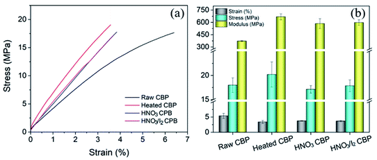 | ||
| Fig. 8 (a) The mechanical properties of CBP after various post treatments. (b) Tensile strength, failure strain and tensile modulus extracted from the curves in (a). | ||
Conclusion
We have demonstrated an effective chemical doping method that uses oxidant dopant (i.e. HNO3 and I2) to increase the hole concentration and mobility to produce a high electrically conductive CBP. In combination with the scalable roll-to-roll CBP manufacturing process, chemical doping induced high electrical conductivity. Furthermore, long-term performance stability was assisted and achieved by a conductive polymer coating layer of PEDOT:PSS. This scale-up manufacturing effort produces highly conductive CBP materials that can enable engineering applications, such as cabling, EMI shielding, flexible electronics, or electrodes for energy storage devices.Conflicts of interest
There are no conflicts to declare.Acknowledgements
This research is supported by NSF SNM program (# 1344672) and High-Performance Materials Institute at Florida State University. Songlin Zhang also thanks the support from China Scholarship Council (CSC no. 201506630022).Notes and references
- S. Iijima, nature, 1991, 354, 56–58 CrossRef CAS.
- T. W. Ebbesen, H. J. Lezec, H. Hiura, J. W. Bennett, H. F. Ghaemi and T. Thio, Nature, 1996, 382, 54–56 CrossRef CAS.
- L. Kurzepa, A. Lekawa-Raus, J. Patmore and K. Koziol, Adv. Funct. Mater., 2014, 24, 619–624 CrossRef CAS.
- A. Lekawa-Raus, J. Patmore, L. Kurzepa, J. Bulmer and K. Koziol, Adv. Funct. Mater., 2014, 24, 3661–3682 CrossRef CAS.
- F. Guo, C. Li, J. Wei, R. Xu, Z. Zhang, X. Cui, K. Wang and D. Wu, Mater. Res. Express, 2015, 2, 095604 CrossRef.
- M. B. Jakubinek, M. B. Johnson, M. A. White, C. Jayasinghe, G. Li, W. Cho, M. J. Schulz and V. Shanov, Carbon, 2012, 50, 244–248 CrossRef CAS.
- J.-H. Pöhls, M. B. Johnson, M. A. White, R. Malik, B. Ruff, C. Jayasinghe, M. J. Schulz and V. Shanov, Carbon, 2012, 50, 4175–4183 CrossRef.
- J. N. Wang, X. G. Luo, T. Wu and Y. Chen, Nat. Commun., 2014, 5, 3848 CAS.
- J. Alvarenga, P. R. Jarosz, C. M. Schauerman, B. T. Moses, B. J. Landi, C. D. Cress and R. P. Raffaelle, Appl. Phys. Lett., 2010, 97, 182106 CrossRef.
- J. G. Park, J. Smithyman, C.-Y. Lin, A. Cooke, A. W. Kismarahardja, S. Li, R. Liang, J. S. Brooks, C. Zhang and B. Wang, J. Appl. Phys., 2009, 106, 104310 CrossRef.
- I. W. Chen, Chem. Commun., 2013, 49, 2753–2755 RSC.
- I. W. Chen, R. Liang, H. Zhao, B. Wang and C. Zhang, Nanotechnology, 2011, 22, 485708 CrossRef PubMed.
- N. Nguyen, E. Melamed, J. G. Park, S. Zhang, A. Hao and R. Liang, Macromol. Mater. Eng., 2017, 302, 1700135 CrossRef.
- J.-H. Lin, Z.-I. Lin, Y.-J. Pan, C.-T. Hsieh, M.-C. Lee and C.-W. Lou, Composites, Part A, 2016, 84, 354–363 CrossRef CAS.
- P. Liu, D. C. M. Hu, T. Q. Tran, D. Jewell and H. M. Duong, Colloids Surf., A, 2016, 509, 384–389 CrossRef CAS.
- T. Q. Tran, Z. Fan, P. Liu, S. M. Myint and H. M. Duong, Carbon, 2016, 99, 407–415 CrossRef CAS.
- L. Zeng, H. Mou, Y. Qiao, G. Chen, J. Xu and P. Liu, J. Appl. Polym. Sci., 2017, 134, 44609 CrossRef.
- M. Zhang, K. R. Atkinson and R. H. Baughman, Science, 2004, 306, 1358–1361 CrossRef CAS PubMed.
- X. Wu, T. Morimoto, K. Mukai, K. Asaka and T. Okazaki, J. Phys. Chem. C, 2016, 120, 20419–20427 CAS.
- X. G. Luo, X. X. Huang, X. X. Wang, X. H. Zhong, X. X. Meng and J. N. Wang, ACS Appl. Mater. Interfaces, 2016, 8, 7818–7825 CAS.
- Y. Inoue, Y. Suzuki, Y. Minami, J. Muramatsu, Y. Shimamura, K. Suzuki, A. Ghemes, M. Okada, S. Sakakibara, H. Mimura and K. Naito, Carbon, 2011, 49, 2437–2443 CrossRef CAS.
- H. Gerald and Z. Liang, US Pat., 9,909,259, March 6, 2018.
- N. Nguyen, A. Hao, J. G. Park and R. Liang, Adv. Eng. Mater., 2016, 18, 1906–1912 CrossRef CAS.
- N. Behabtu, C. C. Young, D. E. Tsentalovich, O. Kleinerman, X. Wang, A. W. Ma, E. A. Bengio, R. F. ter Waarbeek, J. J. de Jong and R. E. Hoogerwerf, Science, 2013, 339, 182–186 CrossRef CAS PubMed.
- X. H. Zhong, Y. L. Li, Y. K. Liu, X. H. Qiao, Y. Feng, J. Liang, J. Jin, L. Zhu, F. Hou and J. Y. Li, Adv. Mater., 2010, 22, 692–696 CrossRef CAS PubMed.
- Y. Shang, Y. Wang, S. Li, C. Hua, M. Zou and A. Cao, Carbon, 2017, 119, 47–55 CrossRef CAS.
- P. Liu, Y. F. Tan, D. C. M. Hu, D. Jewell and H. M. Duong, Mater. Des., 2016, 108, 754–760 CrossRef CAS.
- B. Han, X. Xue, Y. Xu, Z. Zhao, E. Guo, C. Liu, L. Luo and H. Hou, Carbon, 2017, 122, 496–503 CrossRef CAS.
- J. Gao, X. Mu, X. Y. Li, W. Y. Wang, Y. Meng, X. B. Xu, L. T. Chen, L. J. Cui, X. Wu and H. Z. Geng, Nanotechnology, 2013, 24, 435201 CrossRef PubMed.
- G. A. S., Organic Light Emitting Diodes (OLEDs): Technologies and Global Markets, Report SMC069D, BCC Research, 2015 Search PubMed.
- M. J. Casavant, D. A. Walters, J. J. Schmidt and R. E. Smalley, J. Appl. Phys., 2003, 93, 2153–2156 CrossRef CAS.
- Y. Han, X. Zhang, X. Yu, J. Zhao, S. Li, F. Liu, P. Gao, Y. Zhang, T. Zhao and Q. Li, Sci. Rep., 2015, 5, 11533 CrossRef PubMed.
- Q. Cheng, J. Bao, J. Park, Z. Liang, C. Zhang and B. Wang, Adv. Funct. Mater., 2009, 19, 3219–3225 CrossRef CAS.
- S. Zhang, J. G. Park, N. Nguyen, C. Jolowsky, A. Hao and R. Liang, Carbon, 2017, 125, 649–658 CrossRef CAS.
- L. D'Arsie, S. Esconjauregui, R. S. Weatherup, X. Y. Wu, W. E. Arter, H. Sugime, C. Cepek and J. Robertson, RSC Adv., 2016, 6, 113185–113192 RSC.
- H. J. Lee, Y. S. Song, T. K. An, W. K. Choi and S. R. Kim, Synth. Met., 2016, 221, 340–344 CrossRef CAS.
- D. Janas, A. P. Herman, S. Boncel and K. K. K. Koziol, Carbon, 2014, 73, 225–233 CrossRef CAS.
- D. Janas, K. Z. Milowska, P. D. Bristowe and K. K. Koziol, Nanoscale, 2017, 9, 3212–3221 RSC.
- L.-n. Fan and X.-c. Xu, Compos. Sci. Technol., 2015, 118, 264–268 CrossRef CAS.
- Y. Zhao, J. Wei, R. Vajtai, P. M. Ajayan and E. V. Barrera, Sci. Rep., 2011, 1, 83 CrossRef PubMed.
- A. A. Tonkikh, V. I. Tsebro, E. A. Obraztsova, K. Suenaga, H. Kataura, A. G. Nasibulin, E. I. Kauppinen and E. D. Obraztsova, Carbon, 2015, 94, 768–774 CrossRef CAS.
- A. Morelos-Gómez, M. Fujishige, S. Magdalena Vega-Díaz, I. Ito, T. Fukuyo, R. Cruz-Silva, F. Tristán-López, K. Fujisawa, T. Fujimori, R. Futamura, K. Kaneko, K. Takeuchi, T. Hayashi, Y. A. Kim, M. Terrones, M. Endo and M. S. Dresselhaus, J. Mater. Chem. A, 2016, 4, 74–82 Search PubMed.
- T. Chen, H. Peng, M. Durstock and L. Dai, Sci. Rep., 2014, 4, 3612 CrossRef PubMed.
- C. Feng, K. Liu, J.-S. Wu, L. Liu, J.-S. Cheng, Y. Zhang, Y. Sun, Q. Li, S. Fan and K. Jiang, Adv. Funct. Mater., 2010, 20, 885–891 CrossRef CAS.
- R. A. Susantyoko, Z. Karam, S. Alkhoori, I. Mustafa, C.-H. Wu and S. Almheiri, J. Mater. Chem. A, 2017, 5, 19255–19266 CAS.
- K. Mukai, K. Asaka, T. Sugino, K. Kiyohara, I. Takeuchi, N. Terasawa, D. N. Futaba, K. Hata, T. Fukushima and T. Aida, Adv. Mater., 2009, 21, 1582–1585 CrossRef CAS.
- W. Lee, H. Koo, J. Sun, J. Noh, K. S. Kwon, C. Yeom, Y. Choi, K. Chen, A. Javey and G. Cho, Sci. Rep., 2015, 5, 17707 CrossRef CAS PubMed.
- D. D. Tune, A. J. Blanch, C. J. Shearer, K. E. Moore, M. Pfohl, J. G. Shapter and B. S. Flavel, ACS Appl. Mater. Interfaces, 2015, 7, 25857–25864 CAS.
- X. He, W. Gao, L. Xie, B. Li, Q. Zhang, S. Lei, J. M. Robinson, E. H. Haroz, S. K. Doorn, W. Wang, R. Vajtai, P. M. Ajayan, W. W. Adams, R. H. Hauge and J. Kono, Nat. Nanotechnol., 2016, 11, 633–638 CrossRef CAS PubMed.
- S. Lu, J. Shao, K. Ma, X. Wang, L. Zhang and Q. Meng, J. Phys. D: Appl. Phys., 2016, 49, 445308 CrossRef.
- M.-c. Yang, M.-y. Li, S. Luo and R. Liang, Int. J. Adv. Manuf. Technol., 2015, 82, 361–367 CrossRef.
- Q. W. Li, Y. Li, X. F. Zhang, S. B. Chikkannanavar, Y. H. Zhao, A. M. Dangelewicz, L. X. Zheng, S. K. Doorn, Q. X. Jia, D. E. Peterson, P. N. Arendt and Y. T. Zhu, Adv. Mater., 2007, 19, 3358–3363 CrossRef CAS.
- Z. Wu, Y. Han, R. Huang, X. Chen, Y. Guo, Y. He, W. Li, Y. Cai and N. Wang, Nanoscale, 2014, 6, 13196–13202 RSC.
- R. Jackson, B. Domercq, R. Jain, B. Kippelen and S. Graham, Adv. Funct. Mater., 2008, 18, 2548–2554 CrossRef CAS.
- U. Dettlaff-Weglikowska, V. Skákalová, R. Graupner, S. H. Jhang, B. H. Kim, H. J. Lee, L. Ley, Y. W. Park, S. Berber, D. Tománek and S. Roth, J. Am. Chem. Soc., 2005, 127, 5125–5131 CrossRef CAS PubMed.
| This journal is © The Royal Society of Chemistry 2018 |


