DOI:
10.1039/C8RA01129J
(Paper)
RSC Adv., 2018,
8, 19171-19180
Fabrication of low-density carbon-bonded carbon fiber composites with an Hf-based coating for high temperature applications
Received
5th February 2018
, Accepted 5th May 2018
First published on 24th May 2018
Abstract
A novel Hf-based anti-oxidation coating has been prepared on the surface of low-density carbon-bonded carbon fiber composites (CBCFs). The coating exhibits a gradient transition structure, with mainly HfB2, Hf2Si and SiC ceramics. Oxyacetylene torch testing has been utilized to evaluate the ablation resistance under the condition ranging from 1.6 MW m−2 to 2.2 MW m−2 for 300 s. The experimental results show that the as-prepared Hf-based coating can effectively protect CBCFs under high-temperature oxidation conditions. The surface maximum temperature can reach 1616–2037 °C, and the mass ablation rates vary from −3.5 × 10⁻⁵ g s−1 cm−2 to 1.5 × 10⁻⁵ g s−1 cm−2. The formation of a dense SiO2 glass layer embedded with HfO2 grains or particle accumulation in the HfO2 layer is responsible for the good ablation resistance.
1. Introduction
Thermal protection system (TPS) is one of the key technologies of aerospace vehicle design and development. A lot of manpower and financial resources have been invested in the development of high-performance and reliable thermal protection materials and structures for their use in space.1,2 In recent years, the development of a large number of new low-density materials has raised research interests in lightweight thermal protection materials such as phenolic impregnated carbon ablator (PICA),3,4 SIRCA,5,6 and toughened uni-piece fibrous reinforced oxidization-resistant composites (TUFROC).7–10 Specifically, TUFROC has become desirable due to its unique properties including lightweightedness, low thermal conductivity, high temperature stability and low cost.9,10 TUFROC has a two-piece structure, with a treated carbonaceous cap, namely, refractory oxidation-resistant ceramic carbon insulation (ROCCI) and a fibrous insulation base, namely, toughened uni-piece fibrous insulation (TUFI)-treated alumina-enhanced thermal barrier (AETB).7 In this study, we focused on one kind of ROCCI, that is, carbon-bonded carbon fiber composites (CBCFs).
CBCFs are typical porous carbon–carbon (C/C) composites with low densities of 0.1–0.5 g cm−3 and high open porosities over 70%.11–13 They are thought to be desirable candidates for high-temperature heat insulation applications14,15 and thermal insulation applications in aerospace13,16,17 due to their unique properties such as lightweightedness, low thermal conductivity, and high temperature stability However, low mechanical properties and poor oxidation resistance limit the wide applications of monolithic CBCFs. Recently, many research studies have been carried out to solve these problems.18–23 Carbon nanotubes (CNTs)19 and SiC nanowires (SiCNWs)22 have been used to improve the mechanical properties of CBCFs. Various Si-based coatings (including MoSi2 and TaSi2)24 and Zr-based coatings (such as ZrB2)19,25 have been widely investigated as an attractive way to ameliorate CBCFs' antioxidant properties. Unfortunately, up to now, the effective temperature of the anti-oxidation method has been limited to 1700 °C. To the best of our knowledge, reports on high or ultra-high temperature oxidation resistance of CBCFs are limited.
In this paper, a new type of Hf-based anti-oxidation coating was designed and prepared to protect CBCFs for use at high temperature. The microstructure and the oxidation behavior of the coated CBCF composites were analyzed and discussed in detail. The results showed that the as-prepared Hf-based anti-oxidation coating could protect CBCFs under aerobic conditions at a maximum temperature range of ∼1616 °C to 2037 °C.
2. Experimental
2.1 Preparation of CBCFs
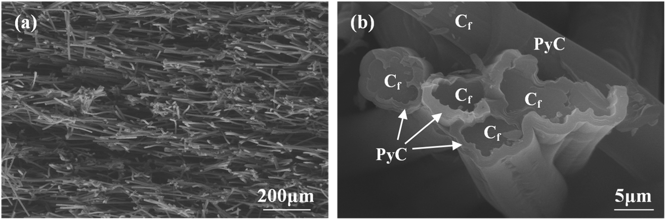
Rayon-based carbon fibers with 0.8 mm length were used to prepare CBCFs by dispersion and filtration technique. The details of the preparations were given in our previous study.18 In the present study, to improve the mechanical properties of CBCFs, pyrolytic carbon (PyC) was deposited on the surface of carbon fibers through chemical vapor infiltration (CVI) at 1000 °C using propane as the carbon source. After deposition for 200 h, the density of CBCFs increased from 0.25 g cm−3 to 0.36 g cm−3, and the open porosity decreased from 85.7% to 79.4%. Fig. 1 shows the microstructures of as-prepared CBCFs after the CVI process. The characteristics of the random distribution of fibers and the highly porous network did not change as compared to those before CVI (Fig. 1a). A uniform PyC layer with a thickness of about 1 μm was formed on the surface of the carbon fibers, as shown in Fig. 1b.
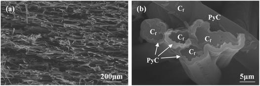 |
| | Fig. 1 SEM images of PyC-coated CBCFs after CVI: (a) low magnification; (b) high magnification in (a). | |
2.2 Preparation of high temperature Hf-based anti-oxidation coating on CBCFs
Commercially available Hf powder (1–3 μm, purity 99.5%, Northwest Institute for Non-ferrous Metal Research, China), Si powder (1–2 μm, purity 99.9%, Weifang Kaihua Micro-powder Co. Ltd., China), B (1–2 μm, purity 99.5%, Alfa Aesar (China) Chemicals Co. Ltd.) were used in this study.
The cylindrical samples (Φ25.4 × 8 mm) used as substrates were cut from PyC-coated CBCFs. The samples were cleaned ultrasonically with ethanol and dried at 120 °C for 2 h. The Hf-based anti-oxidation coating was prepared by a simple SIR method, namely, slurry brushing, followed by infiltration processing and reactive sintering. The powdered mixtures of Hf (80 wt%), Si (15 wt%) and B (5 wt%) were ball-milled for 10 h. After mixing, the mixtures were added to a silicon resin to form a mixed slurry. Then, the Hf-based anti-oxidation coating was prepared by slurry brushing and infiltration processing using the above-mentioned mixed slurry. After drying at 200 °C for 2 h, the impregnated samples were sintered at 1550 °C for 120 min in a high-temperature vacuum furnace. The thickness of this infiltration layer was controlled by changing the brush and pyrolysis cycles, which was different to the processes used in vacuum slurry infiltration methods.26
2.3 Ablation tests and characterization
The ablation behaviors of the as-prepared CBCFs with the Hf-based oxidation coating were evaluated under simulated atmospheric conditions using an oxyacetylene torch. Cylindrical-shaped samples with a size of ϕ25.4 mm × 8 mm were used in this study. The as-prepared CBCFs with the Hf-based oxidation coating having these dimensions had a bulk density of 0.8 g cm−3. During the ablation test, a water-cooled Gardon gauge was used to calibrate the heat flux, and a two-color pyrometer was used to record the surface temperature. Three typical ablation conditions were chosen by adjusting the ratio of acetylene to oxygen, i.e., 0.6![[thin space (1/6-em)]](https://www.rsc.org/images/entities/char_2009.gif) :0.4, 0.7:0.4 and 0.8:0.5, as shown in Table 1; the corresponding heat fluxes and testing samples were 1.6 MW m−2 (S1), 1.8 MW m−2 (S2) and 2.2 MW m−2 (S3). The distance from the nozzle tip of the oxyacetylene gun to the samples was about 40 mm. The exposure time was 300 s. The mass ablation rates were calculated by the following formula:
:0.4, 0.7:0.4 and 0.8:0.5, as shown in Table 1; the corresponding heat fluxes and testing samples were 1.6 MW m−2 (S1), 1.8 MW m−2 (S2) and 2.2 MW m−2 (S3). The distance from the nozzle tip of the oxyacetylene gun to the samples was about 40 mm. The exposure time was 300 s. The mass ablation rates were calculated by the following formula:| |
 | (1) |
Table 1 Ablation properties of CBCFs with the Hf-based oxidation coating for 300 s
| Samples |
O2:C2H2 |
H (MW m−2) |
t (s) |
Tmax (°C) |
Rm (g cm−2 s−1) |
| S1 |
0.6:0.4 |
1.6 |
300 |
1616 |
−3.5 × 10⁻⁵ |
| S2 |
0.7:0.4 |
1.8 |
300 |
1830 |
−1.7 × 10⁻⁵ |
| S3 |
0.8:0.5 |
2.2 |
300 |
2037 |
1.5 × 10⁻⁵ |
Here, Rm is the mass ablation rate; m0 and m1 are the masses of the samples before and after ablation, respectively; s is the ablation area of the surface and t is the ablation time.
The positive values of Rm represent weight losses, and negative values represent weight gains.
The phase composition was determined via X-ray diffraction using Cu Kα radiation. Surface and cross-sectional morphologies of the coatings before and after the ablation tests were observed using scanning electron microscopy (SEM) with simultaneous chemical analysis by energy dispersive spectroscopy (EDS).
3. Results and discussion
3.1 Microstructure of the as-prepared Hf-based coated CBCFs
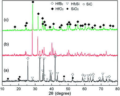
The morphology of the prepared Hf-based surface coating is displayed in Fig. 2. As shown in Fig. 2a, the surface coating exhibits a typical rough structure without the formation of macro-cracks, which demonstrates the physical compatibility of the coating with CBCFs. The details corresponding to elemental distribution maps are shown in Fig. 2b–e, which exhibit the uniform dispersions of Hf, Si, B and C. Fig. 3 shows the surface XRD results of the prepared Hf-based coating. Based on the diffraction peaks, the main phases in the coating are mainly HfB2, Hf2Si and SiC. A small amount of residual Si is also detected by XRD. The results indicate that most of the impregnated ceramic powders have reacted in situ with each other or with carbon to form the HfB2–Hf2Si–SiC coating, which can afford good oxidation protection under high temperature.27,28
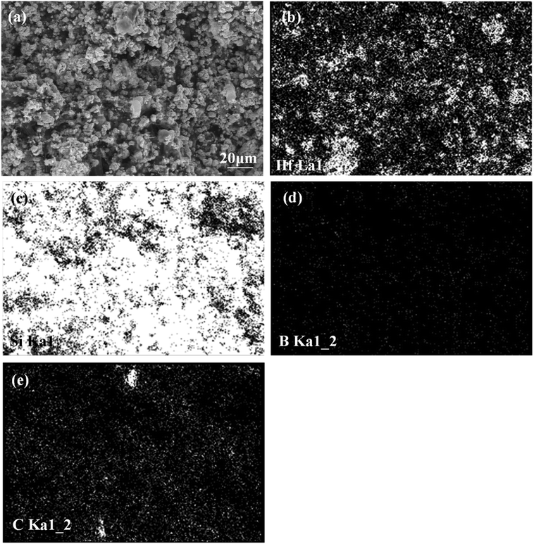 |
| | Fig. 2 SEM micrograph and the corresponding elemental distribution maps of Hf-based anti-oxidation coating: (a) SEM image; (b) Hf distribution; (c) Si distribution; (d) B distribution, (e) C distribution. | |
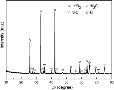 |
| | Fig. 3 XRD pattern of the prepared coating. | |
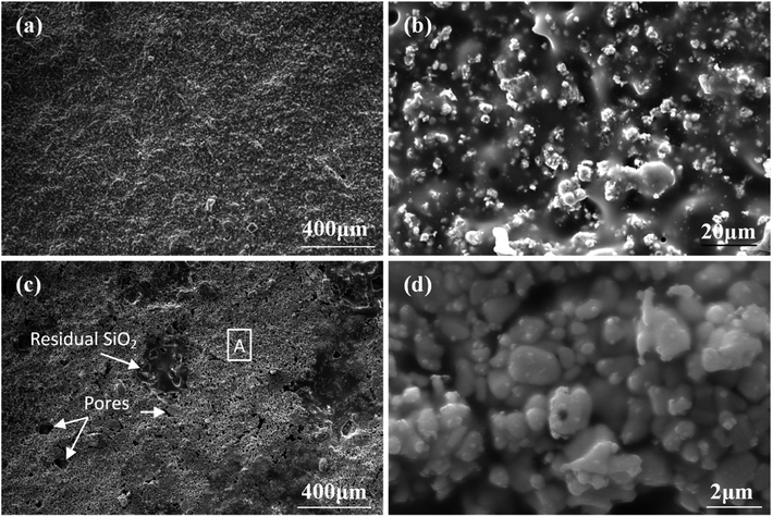
Fig. 4 displays the cross-sectional morphologies of the as-prepared Hf-based anti-oxidation coating. It can be found that the oxidation coating is about 300 μm in thickness, and there are no clear penetration cracks between the oxidation coating layer and CBCFs, revealing good compatibility between the layers (Fig. 4a). Moreover, as shown in Fig. 4b and c, two oxidation layers can be found: an inner layer with a porous structure (∼600 μm in thickness) and an outer layer with a more compact structure at the top of the coating layer (∼100 μm in thickness). The main phases including white HfB2 and Hf2Si (marked as H) and gray SiC (marked as S) are dispersed homogenously in the outer coating (Fig. 4b). The Hf-based anti-oxidation coating can penetrate into CBCFs to form an inner layer with porous carbon fiber embedded within the white Hf-based phase and gray SiC phase; the carbon fibers are marked as Cf and the pores are marked as P (Fig. 4c). Thus, the results clearly reveal that a gradient structure oxidation layer can be prepared using this SIR processing in the present study, which is beneficial to enhance the impact resistance and the thermal expansion matching between the coating and CBCFs, which is similar to the observations for the TUFI coating of ROCCI.7,9 Meanwhile, it is clear that the carbon fibers are covered with a thin layer of PyC, as shown in Fig. 4d, which is beneficial to improve the mechanical properties since it increases preform stiffness and prevents damage to the carbon fibers in the SIR processing.20 In the present study, with the introduction of PyC interface, the compressive strength is improved from 0.22 MPa to 0.97 MPa, with a 341% improvement as compared with that for the original CBCFs.
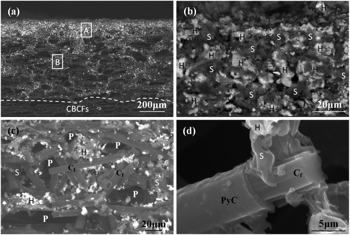 |
| | Fig. 4 Cross-sectional SEM images of the prepared coatings: (a) low magnification; (b) and (c) high magnification corresponding to regions A and B in (a), respectively; (d) high magnification of (c). | |
3.2 Ablation properties of CBCFs with the Hf-based coating
The ablation test results are summarized in Table 1, illustrating the maximum surface temperatures of S1, S2 and S3 as 1616 °C, 1830 °C and 2037 °C, respectively. This indicates that the surface temperature increases monotonously with the heat flux from 1.6 MW m−2 to 1.8 MW m−2 and 2.2 MW m−2. At the same total exposure time of 300 s, the mass ablation rates vary from −3.5 × 10⁻⁵ g s−1 cm−2 (S1) to −1.7 × 10⁻⁵ g s−1 cm−2 (S2) and then to 1.5 × 10⁻⁵ g s−1 cm−2 (S3), and they increase with the heat flux. Meanwhile, clearly, the thicknesses of all samples did not change.
Time-surface temperature data under different heat flux conditions are shown in Fig. 5. The macrographs of the coated samples after ablation are shown in Fig. 6. The un-ablated surface is compact and gray in color (Fig. 6a). After ablation at 1.6 MW m−2, the coated surface turns black with many glassy oxidation products, as shown in Fig. 6b. During the whole ablation process of 300 s, the oxidizing reaction on the surface tends to be steady, and the temperature is also steady at around 1600 °C (Fig. 5). However, when the ablation heat flux increases to 1.8 MW m−2, the surface temperature of the ablation center region rapidly reaches about 1700 °C and remains stable for about 250 s, followed by a slow increase to a maximum temperature of 1830 °C, as shown in Fig. 5. At this high temperature condition, an oxidation surface mixture with black and white phases is formed on the surface of S2 (Fig. 6c). When the heat flux further increases to 2.2 MW m−2, the temperature rapidly reaches around 1730 °C and then, it further increases to 2037 °C at 170 s and remains steady for the last 130 s. During this condition, more white oxidation products can be found on the surface of S3, as shown in Fig. 6d. All the CBCF samples with Hf-based coatings appear without cracks and spallation on the surface during the test. It should be pointed out that according to Fig. 5, temperature jump phenomena are detected for S2 and S3 probably due to the formation of white products, which is different from the observations for C/SiC and C/SiC-HfC composites.28,29 Additional experimental verification including theoretical analysis is needed to explain the temperature jump phenomenon of Hf-based CBCFs under an oxidation environment.
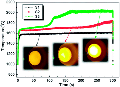 |
| | Fig. 5 Surface temperatures measured during ablation testing for different samples. | |
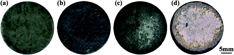 |
| | Fig. 6 Macro-photographs of CBCFs with the Hf-based oxidation coating before and after the ablation test for 300 s: (a) before ablation; (b) after ablation of S1; (c) after ablation of S2; (d) after ablation of S3. | |
3.3 Microstructure evolution of CBCFs with the Hf-based coating after ablation
Fig. 7 exhibits the XRD patterns of CBCFs with the Hf-based coatings after ablation testing. Different phases were formed under different heat fluxes at the same exposure time. It was clear that the identified phases on the surface of S1 were composed of HfB2, Hf2Si and SiC from the original coating as well as the new phase of SiO2, as shown in Fig. 7a. When the maximum surface temperature increased up to 1830 °C, the peaks were mainly of HfO2 and SiO2 along with those corresponding to small amounts of HfB2 and Hf2Si, implying that the oxidation coating of S2 was partly oxidized (Fig. 7b). When the surface temperature further increased up to 2037 °C, it was found that only HfO2 was present, indicating that the surface of S3 was completely oxidized (Fig. 7c), and these results were in good accordance with the results of macrograph analysis (Fig. 6d).
 |
| | Fig. 7 XRD patterns of different CBCFs with the Hf-based oxidation coating after ablation for 300 s: (a) S1; (b) S2; (c) S3. | |
To further understand the ablation behaviors of different samples, the evolution of surface microstructure has been investigated. As shown in Fig. 8, the oxidized surface of S1 was covered with a dense gray glassy layer embedded within a white phase. According to EDS and XRD analyses (Fig. 7 and 8), the gray glassy layer was SiO2, and the white phase was composed of Hf, O and Si, which might have been HfO2 oxide grains covered with an amorphous silica layer. The element Ir was detected from the surface spray process of SEM analysis. In addition, no clear cracks were found on the surface due to the crack-sealing function of the glassy phase, which could prevent the oxygen diffusion and protect the layers beneath.
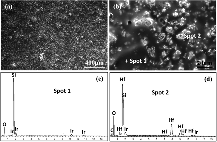 |
| | Fig. 8 Surface morphologies of S1 after ablation for 300 s: (a) low magnification; (b) high magnification of (a); (c) and (d) EDS patterns corresponding to spot 1 and spot 2 in (b), respectively. | |
As indicated in Fig. 9, there are two typical ablation regions on the surface of S2: the brim ablation region and the ablation center region. The brim ablation region was covered with a gray coating embedded within the white phase similar to the observations for the surface of S1 (Fig. 9a and b), which meant that both samples experienced equivalent environments. According to literature,30 the temperature of the ablation center region is much higher than that of the brim ablation region under the vertically jetted flowing oxyacetylene torch testing environment. When the maximum temperature was increased to 1830 °C in the ablation center region, the vapor pressure of SiO2 increased substantially,31 leading to its evaporation; also, SiO2 was blown away due to the impact of oxyacetylene torch. Traces of gas volatilization were easily observed, and the ablation center zone was coated by a large number of fine HfO2 grains (about 0.5–2 μm in size) with no exposed substrate, as shown in Fig. 9c and d.
 |
| | Fig. 9 Surface morphologies of S2 after oxyacetylene test for 300 s: (a) low magnification of the brim region; (b) high magnification of (a); (c) low magnification of the ablation center region; (d) high magnification corresponding to region A in (c). | |
SEM images of oxidized surfaces of S3 are presented in Fig. 10. The surface appeared similar to that of the ablation region of S2 but with a higher amount of HfO2 phase, which was confirmed by EDS. It should be noted that at such a high temperature (maximum being 2037 °C), in addition to the significant evaporation of SiO2 due to its low viscosity, the problem of the active oxidation of SiC was taken into consideration in the present study. The thermal stability of refractory carbide/boride composites in an oxidizing environment has been studied by Wang et al.32 The results confirmed that at a high temperature or a low oxygen partial pressure, SiC underwent a transition from passive to active oxidation, and the protective SiO2 layer was removed as SiO (g). Furthermore, two kinds of HfO2 phases were detected on the surface of ablated S3, as shown in Fig. 10. One consisted of fine HfO2 grains with an average size larger than that of the ablation region of S2, which was about −5 μm (Fig. 10c). The other was similar to molten HfO2 with a much larger size of over 10 μm (Fig. 10b). Additionally, no carbon fibers were detected, indicating that the HfO2 layer could withstand the high-speed oxyacetylene torch flame and serve as an effective insulator to resist the high-temperature ablation.
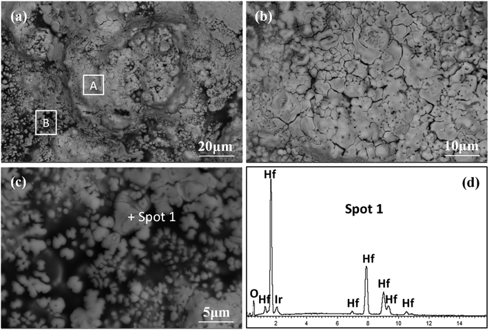 |
| | Fig. 10 Surface morphologies of S3 after oxyacetylene test for 300 s: (a) low magnification; (b) and (c) high magnification corresponding to regions A and B in (a), respectively; (d) EDS pattern corresponding to spot 1 in (c). | |
3.4 Ablation mechanism
As shown in Fig. 11, a schematic diagram is used to explain the ablation mechanism of CBCFs with the Hf-based coating under different testing environments. During the ablation testing process, the coated CBCFs react with oxygen as follows:33–35| | |
HfB2(s) + 5/2O2(g) = HfO2(s) + B2O3(l)
| (2) |
| | |
Hf2Si(s) + 3O2(g) = 2HfO2(s) +SiO2(l)
| (3) |
| | |
SiC(s) + 3/2O2(g) = SiO2(l) + CO(l)
| (4) |
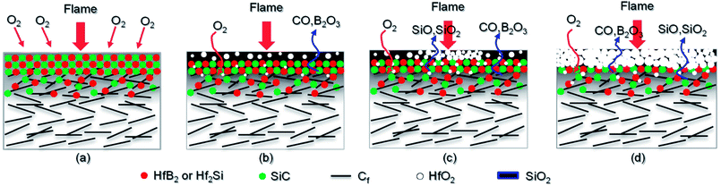 |
| | Fig. 11 Schematic diagram for the ablation of CBCFs with the Hf-based coating: (a) initial stage of ablation; (b) S1; (c) S2; (d) S3. | |
When the ablation was started, the outer coating was exposed to the flame in the oxygen-rich environment. The surface temperature rose rapidly to the testing temperature within 10 s (Fig. 5). When the temperature approached 1600 °C for S1, HfB2, Hf2Si and SiC were quickly oxidized to form an oxidation layer on the surface of the coated CBCFs, according to Reactions (2)–(4). A gray glassy layer of SiO2 embedded within HfO2 was formed on the surface, as shown in Fig. 11b. No B2O3 was detected through XRD or EDS analysis; it must have vaporized in the testing environment due to its low melting point and high vapor pressure.36 In addition, there was no clear crack on the surface, which may be attributed to the possibility that the glassy phase effectively sealed the microcracks during ablation, and this could prevent the oxygen diffusion and protect the matrix beneath.
When the heat flux increase to 1.8 MW m−2 for S2, the Hf-based anti-oxidation coating underwent different ablation environments due to the different temperature distribution on the surface. At the low temperature condition in the brim zone, a protective glass layer was formed, and it acted as a barrier to prevent further diffusion of oxygen (Fig. 11c). However, at the high temperature condition in the ablation region, the efficiency of SiC significantly decreased due to its rapid evaporation and active oxidation, according to Reaction (6). Residual SiO2 and micropores were left after the evaporation of different gases such as SiO, SiO2, CO and B2O3, as shown in Fig. 11c.
With the further increase of heat flux to 2.2 MW m−2 for S3, the coating was gradually oxidized, and the glass phases on the surface were completely evaporated leaving only HfO2, as shown in Fig. 11d. Therefore, a mass loss occurred in S3, which was different to the observations for S1 and S2 (Table 1). However, the surfaces of the composites were almost integrated, and they were fully covered with HfO2 grains. In addition, there were no bare fibers, which indicated the excellent oxidation protection of the as-prepared CBCFs with the Hf-based coating at 2.2 MW m−2 with the maximum temperature approaching 2037 °C for 300 s. Due to the complexity of the high temperature reaction and phase evolution, new fine detection techniques such as Raman spectroscopy, FESEM and TEM EDAX might be used in our future research.37,38
4. Conclusions
In this study, a new type of Hf-based coating was designed and prepared to prevent the oxidation of CBCFs at high temperature. The as-prepared coating had a gradient transition structure, and it was about 300 μm in thickness. No visible macrocracks were detected during the fabrication process and the high-temperature testing/cooling process, owing to the good performance of CBCFs with the Hf-based coating. The mass ablation rates of S1 and S2 were only −3.5 × 10⁻⁵ g s−1 cm−2 and −1.7 × 10⁻⁵ g s−1 cm−2 after 300 s, with the maximum surface temperatures being 1616 °C and 1830 °C, respectively. Meanwhile, the mass ablation rate of S3 was 1.5 × 10⁻⁵ g s−1 cm−2 after ablation for 300 s, with the maximum temperature approaching 2037 °C. Overall, the as-prepared Hf-based coating exhibited excellent ablation resistance to protect CBCFs. The results presented in this paper suggest that CBCFs with the Hf-based coating are important considerations for potential applications in future TPS, which requires lightweight, high performance and low cost materials.
Conflicts of interest
There are no conflicts to declare.
Acknowledgements
This study was finically supported by the National Basic Research Program of China (2015CB655200), the National Natural Science Foundation of China (51702076) and the Open Research Fund of Science and Technology on High Strength Structure Materials Laboratory.
References
- D. E. Glass, Ceramic matrix composite (CMC) thermal protection systems (TPS) and hot structures for hypersonic vehicles, 15th AIAA Space Planes and Hypersonic Systems and Technologies Conference, AIAA, 2008 Search PubMed.
- D. E. Glass, R. Dirling, H. Croop, T. J. Fry and G. J. Frank. Materials development for hypersonic flight vehicles, 14th AIAA/AHI Space Planes and Hypersonic Systems and Technologies Conference, AIAA, 2006 Search PubMed.
- S. M. Johnson, M. J. Gasch, D. Leiser and D. Stewart, Development of new TPS at NASA ames research center, 15th AIAA International Space Planes and Hypersonic Systems and Technologies Conference, AIAA, 2008 Search PubMed.
- H. K. Tran, C. E. Johnson, D. J. Rasky, F. C. L. Hui, M. T. Hsu, T. Chen, Y. K. Chen, D. Paragas and L. Kobayashi. Phenolic impregnated carbon ablators (PICA) as thermal protection systems for discovery missions, NASA Technical Memorandum 110440, 1997 Search PubMed.
- H. K. Tran, C. E. Johnson, D. J. Rasky, F. C. L. Hui and M. T. Hsu. Silicone impregnated reusable ceramic ablators for mars follow-on missions, 31st AIAA Thermophysics Conference, AIAA, 1996 Search PubMed.
- S. A. Sepka and J. A. Samareh, Thermal protection system mass estimating relationships for blunt-body earth entry spacecraft, 45th AIAA Thermophysics Conference, AIAA AVIATION Forum, AIAA, 2015 Search PubMed.
- D. A. Stewart and D. B. Leiser. Toughened uni-piece fibrous reinforced oxidization-resistant composites. US Pat., US7381459B1, 2008.
- D. A. Stewart, D. B. Leiser and R. R. Difiore. High efficiency tantalum-based ceramic composite structures. US Pat., US7767305B1, 2008.
- D. A. Stewart and D. B. Leiser, Lightweight TUFROC TPS for hypersonic vehicles, 14th AIAA/AHI Space Planes and Hypersonic Systems and Technologies Conference, AIAA, 2006 Search PubMed.
- K. Skokova and B. Laub, Experimental evaluation of thermal protection materials for Titan aerocapture, 41st AIAA/ASME/SAE/ASEE Joint Propulsion Conference & Exhibit, AIAA, 2005 Search PubMed.
- I. J. Davies and R. D. Rawlings, Microstructural investigation of low-density carbon-carbon composites, J. Mater. Sci., 1994, 29, 338–344 CrossRef.
- I. J. Davies and R. D. Rawlings, Mechanical properties in compression of low density carbon/carbon composites, Composites, 1994, 25, 229–236 CrossRef.
- C. Liu, J. C. Han, X. H. Zhang, C. Q. Hong and S. Y. Du, Lightweight carbon-bonded carbon fiber composites prepared by pressure filtration technique, Carbon, 2013, 59, 547–554 CrossRef.
- R. I. Baxter, R. D. Rawlings, N. Iwashita and Y. Sawada, Effect of chemical vapor infiltration on erosion and thermal properties of porous carbon/carbon composite thermal insulation, Carbon, 2000, 38, 441–449 CrossRef.
- S. A. Kolesnikov and G. A. Kravetskii, Refractory structures made of low-weight carbon-bonded carbon-fiber-reinforced composites, Refract. Ind. Ceram., 2007, 48, 223–226 CrossRef.
- S. M. Jonson, M. J. Gasch, D. Leiser, D. Stewart, M. Stackpoole and J. Thornton, Development of New TPS at NASA Ames Research Center, 15th AIAA, AIAA, Dayton, Ohio, 2008 Search PubMed.
- B. Helber, O. Chazot, A. Hubin and T. Magin, Microstructure and gas surface interaction studies of a low-density carbon-bonded carbon fiber composite in atmospheric reentry plasmas, Composites, Part A, 2015, 72, 96–107 CrossRef.
- Y. Zhang, Z. X. Lu, Z. Y. Yang, D. H. Zhang, J. J. Shi, Z. S. Yuan and Q. Liu, Compression behaviors of carbon-bonded carbon fiber composites: Experimental and numerical investigations, Carbon, 2017, 116, 398–408 CrossRef.
- B. S. Xu, S. B. Zhou, C. Q. Hong, J. C. Han and X. H. Zhang, Mechanical enhancement of lightweight ZrB2-modified carbon-bonded carbon fiber composites with self grown carbon nanotubes, Carbon, 2016, 102, 487–493 CrossRef.
- X. H. Zhang, B. S. Xu, C. Q. Hong, J. C. Han, F. X. Qin, W. B. Han, H. M. Cheng, C. Liu and R. J. He, Carbon-bonded carbon fiber composites containing uniformly distributed silicon carbide, RSC Adv., 2014, 4, 6591–6596 RSC.
- X. H. Xu, B. S. Xu, C. Q. Hong and D. Hui, Effect of pyrolytic carbon interface thickness on microstructure and mechanical properties of lightweight zirconium boride modified carbon-bonded carbon fiber composites, Composites, Part B, 2016, 96, 305–311 CrossRef.
- J. Li, J. J. Sha, J. X. Dai, Z. Z. Lv, J. Q. Shao, S. H. Wang and Z. F. Zhang, Fabrication and characterization of carbon-bonded carbon fiber composites with in situ grown SiC nanowires, Carbon, 2017, 118, 148–155 CrossRef.
- M. Niu, H. J. Wang, J. B. Wen and X. Fang, Preparation and anti-oxidation properties of Si(O)C coated carbon-bonded carbon fiber composites, RSC Adv., 2015, 5, 52347–52354 RSC.
- B. Du, C. Q. Hong, S. B. Zhou, C. Liu and X. H. Zhang, Multi-composition coating for oxidation protection of modified carbon-bonded carbon fiber composites, J. Eur. Ceram. Soc., 2016, 36, 3303–3310 CrossRef.
- B. S. Xu, R. J. He, C. Q. Hong, Y. B. Ma, W. B. Wen, H. M. Li, T. B. Cheng, D. N. Fang and Y. Z. Yang, Ablation behavior and mechanism of double-layer ZrB2-based ceramic coating for lightweight carbon-bonded carbon fiber composites under oxyacetylene flame at elevate temperature, J. Alloys Compd., 2017, 702, 551–560 CrossRef.
- M. Niu, H. J. Wang, L. Su, D. H. Zhang b and J. J. Shi, Fabrication and properties of lightweight SiOC modified carbon-bonded carbon fiber composites, Ceram. Interfaces, 2016, 42, 10614–10618 CrossRef.
- L. Xue, Z. A. Su, X. Yang, D. Huang, T. Yin, C. X. Liu and Q. Z. Huang, Microstructure and ablation behavior of C/C–HfC composites prepared by precursor infiltration and pyrolysis, Corros. Sci., 2015, 94, 165–170 CrossRef.
- L. Luo, Y. G. Wang, L. Y. Duan, L. P. Liu and G. L. Wang, Ablation behavior of C/SiC–HfC composites in the plasma wind tunnel, J. Eur. Ceram. Soc., 2016, 36, 3801–3807 CrossRef.
- F. Panerai, B. Helber, O. Chazot and M. Balat-Pichelin, Surface temperature jump beyond active oxidation of carbon/silicon carbide composites in extreme aerothermal conditions, Carbon, 2014, 71, 102–119 CrossRef.
- Y. G. Wang, W. Liu, L. F. Cheng and L. T. Zhang, Preparation and properties of 2D C/ZrB2–SiC ultra-high temperature ceramic composites, Mater. Sci. Eng. A, 2009, 524, 129–133 CrossRef.
- J. C. Han, P. Hu, X. H. Zhang, S. H. Meng and W. B. Han, Oxidation-resistant ZrB2–SiC composites at 2200 °C, Compos. Sci. Technol., 2008, 68, 799–806 CrossRef.
- C. R. Wang, J. M. Yang and W. Hoffman, Thermal stability of refractory carbide/boride composites, Mater. Chem. Phys., 2002, 74, 272–281 CrossRef.
- F. Monteverde and A. Bellosi, The resistance to oxidation of an HfB2–SiC composite, J. Eur. Ceram. Soc., 2005, 25, 1025–1031 CrossRef.
- P. Lespadea, N. Richet and P. Goursat, Oxidation resistance of HfB2–SiC composites for protection of carbon-based materials, Acta Astronaut., 2007, 60, 858–864 CrossRef.
- Y. Yang, K. Z. Li, Z. G. Zhao and H. J. Li, Ablation resistance of HfC–SiC coating prepared by supersonic atmospheric plasma spraying for SiC-coated C/C composites, Ceram. Int., 2016, 42, 4768–4774 CrossRef.
- W. B. Han, P. Hu, X. H. Zhang, J. C. Han and S. H. Meng, High temperature oxidation at 1900 °C of ZrB2–xSiC ultrahigh temperature ceramic composites, J. Am. Ceram. Soc., 2008, 91, 3328–3334 CrossRef.
- R. T. Shisode, S. R. Suryawanshi, C. D. Mistari, D. J. Late and M. A. More, Enhanced Field Emission Characteristics of a 3D Hierarchical HfO2–ZnO Heteroarchitecture, ChemistrySelect, 2017, 2, 2305–2310 CrossRef.
- A. B. Phatangare, S. D. Dhole, S. S. Dahiwale, V. L. Mathe, S. V. Bhoraskar, D. J. Late and V. N. Bhoraskar, Surface chemical bonds, surface-enhanced Raman scattering, and dielectric constant of SiO2 nanospheres in situ decorated with Ag-nanoparticles by electron-irradiation, J. Appl. Phys., 2016, 120, 234901 CrossRef.
|
| This journal is © The Royal Society of Chemistry 2018 |
Click here to see how this site uses Cookies. View our privacy policy here. 
 Open Access Article
 This Open Access Article is licensed under a Creative Commons Attribution-Non Commercial 3.0 Unported Licence
 *,
Wenbing Yang,
Zhen Fan,
Xingchao Li,
Wei Li,
Yongzhong Song,
Zhihai Feng and
Dahai Zhang*
*,
Wenbing Yang,
Zhen Fan,
Xingchao Li,
Wei Li,
Yongzhong Song,
Zhihai Feng and
Dahai Zhang*