DOI:
10.1039/C8RA00722E
(Paper)
RSC Adv., 2018,
8, 12138-12145
Microstructure, friction and corrosion resistance properties of a Ni–Co–Al2O3 composite coating
Received
24th January 2018
, Accepted 13th March 2018
First published on 28th March 2018
Abstract
Ni–Co–Al2O3 composite coatings were prepared by pulsed electrodeposition and electrophoresis–electrodeposition on aluminum alloy. The content of Al2O3 particles of the Ni–Co–Al2O3 composite coating prepared by electrophoresis–electrodeposition was significantly higher than the composite coating prepared by pulsed electrodeposition. The composite coating prepared by electrophoresis–electrodeposition exhibited a better anti-wear performance than that prepared by pulsed electrodeposition. The morphology, composition and microstructure of the composite coatings were determined by means of X-ray diffractometer (XRD) and scanning electron microscopy (SEM). The hardness and friction properties of the samples were tested on the microhardness tester and the friction and wear loss tester respectively.
1. Introduction
Aluminum alloys have a wide range of applications in the aerospace, transportation and electronic packaging industries, due to their light weight, high specific strength, good ductility, high thermal conductivity, and low coefficient of thermal expansion. However, their use is limited, due to their low hardness, poor wear and corrosion resistance.1–4 The study of the surface hardness, wear resistance and corrosion resistance of aluminum alloys has become a focus and hotspot of research. Among the many surface modification technologies, electrodeposition is considered one of the most important and cost-effective industrial technologies, because it has the advantages of simple technology, cheap equipment, scalability and so on.5,6
The composite coating has a higher hardness, better wear resistance and corrosion resistance. Therefore, it has wide application prospect. Numerous studies have shown that the hard ceramic particles such as (Al2O3, SiC, Cr2O3, TiO2, WC, diamond) could significantly enhance the mechanical properties and corrosion resistance of the composite coating.7–11 In addition, the content of ceramic particles also affects the performance of the composite coating. In general, the ceramic particles will refine the surface structure of the coating, and they will be uniformly distributed in the coating, which plays a vital role on the properties of the composite coatings.12 In recent years, since electrophoresis has drawn great attention in the preparation of ceramic materials and coatings, it enables a large number of ceramic particles to be uniformly deposited on the surface of a substrate, which achieves a combination of different materials.13–15 In this paper, the same Ni–Co–Al2O3 composite coatings were prepared by different processes (pulsed electrodeposition and electrophoresis–electrodeposition). The content of alumina particles in the composite coating prepared by electrophoresis–electrodeposition is much higher than that of pulsed electrodeposition. The results show that the composite coating prepared by electrophoresis–electrodeposition has more excellent performance in hardness, wear resistance and corrosion resistance than the traditional pulsed electrodeposition composite coating.
2. Experimental details
2.1 Pulse electrodeposition progress
The substrates are LY12 aluminum alloy with size 15 mm × 15 mm × 10 mm, and the average particle size of the alumina particles (α-Al2O3, 99.99% in purity, ST-NANO, China) is 150 nm. The substrate was polished with 2000# abrasive paper and washed in alkaline solution to remove surface oil and then washed in acidic medium to remove the oxide on the surface of magnesium alloy. After each step, the substrates were washed with distilled water. Then the samples were treated in bath which the temperature is 60 °C and the pH value is 3.0–6.0 for 50 min to obtain deposition coating and the concentration of aluminum oxide is 10 g L−1. The deposition voltage was 1.55–1.75 V. The composition of bath was listed in the Table 1.
Table 1 Solution composition
| Reagent |
Value |
Factory |
Purity |
| NiSO4 |
300 g L−1 |
JHD |
>98.5% |
| NiCl |
100 g L−1 |
JHD |
>98% |
| CoSO4 |
20 g L−1 |
JHD |
>99.5% |
| Al2O3 |
10 g L−1 |
ST-NANO |
99.99% |
2.2 Electrophoresis–electrodeposition progress
The sample pretreatment is the same as described above. The sample is placed in an electrophoresis solution of ethanol as a dispersant which the temperature is 55 °C for 300 s to make the Al2O particles electrophoresised to the sample surface, and the composition of the electrophoresis solution are listed in Table 2. The deposition voltage was 60–90 V. Then, the samples were treated in the bath which the composition is same to Table 1 and the experimental conditions is the same to pulse electrodeposition progress.
Table 2 Composition of electrolytic bath
| Reagent |
Value |
Factory |
Purity |
| Al2O3 |
10 g L−1 |
ST-NANO |
99.99% |
| MgCl2·H2O |
5 g L−1 |
Xi'an Chemical Reagent Factory |
>98.0% |
2.3 Characterizations
The cross-sectional and surface morphology of the composite coatings were investigated using scanning electron microscopy (SEM, JSM-6390A, JEOL Ltd., Tokyo, Japan) with an integrated EDS system. The phase structures of the composite coatings were analyzed by X-ray diffraction (XRD-7000; Shimadzu, Tokyo, Japan) with a CuKα radiation. The microindentation hardness of the coatings was measured on the cross-section by a microindentation hardness tester (EM-1500L; Shanghai Everone, Shanghai, China). The load and loading time were 200 gf and 15 seconds. The polarization curves of the samples were determined by CHI760D electrochemical system. The samples were completely immersed in 3.5% NaCl solution for 25 minutes. The friction coefficient of the composite coating was measured using a friction and wear tester (HT-1000; Lanzhou Zhongkai, Lanzhou, China). The test was carried out with disc speed at 560 rpm, using a bearing GCr15 ball (6 mm in diameter) under a load of 5 N for 10 minutes.
3. Results and discussion
3.1 Morphology observation and EDS analysis of Ni–Co–Al2O3 composite coatings
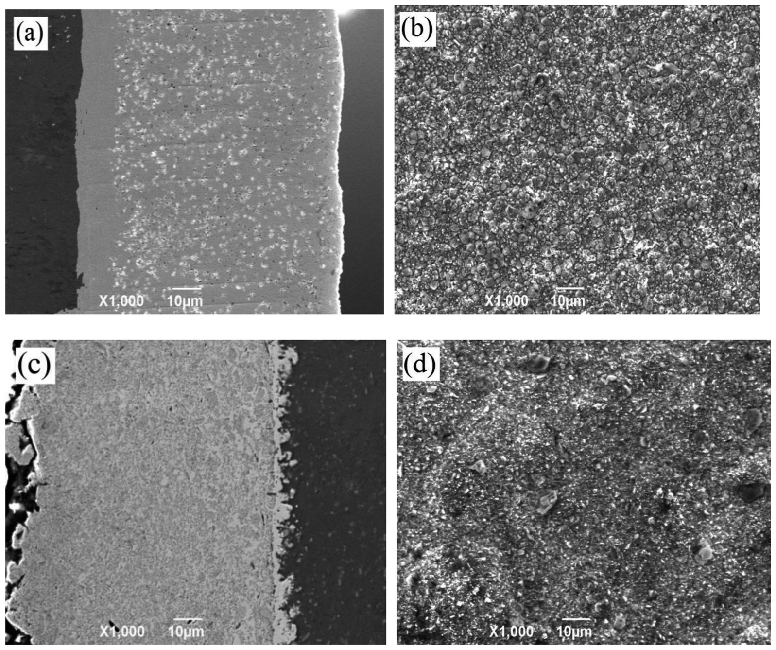
The morphology of the composite coating prepared by electrophoresis–electrodeposition and pulsed electrodeposition is shown in Fig. 1. Fig. 1(a) shows that the cross-sectional morphology of Ni–Co–Al2O3 composite coatings by pulsed electrodeposition. The gray area on the left side is the aluminum alloy matrix, the middle gray and narrow area is the Ni–Co primer layer, and the gray area of the right side is Ni–Co–Al2O3 composite coating. As can be seen from the Fig. 1(a), the Al2O3 particles are uniformly dispersed in the Ni–Co matrix. The binding of the coating with the substrate is well, without particle agglomeration. Fig. 1(b) shows the surface morphology of the Ni–Co–Al2O3 composite coating by pulsed electrodeposition. As shown in Fig. 1(b), the cell structure is homogeneously distributed and is dense. There are no obvious defects and impurities on the coating surface. Fig. 1(c) shows the cross-sectional morphology of the Ni–Co–Al2O3 composite coating prepared by electrophoresis–electrodeposition. In Fig. 1(c), the left side is Ni–Co–Al2O3 composite coating, the middle area is the Ni–Co, and the right side is the aluminum alloy matrix. It is obvious from the left composite coating that a large amount of Al2O3 particles are distributed in the Ni–Co matrix and the content is higher than that of the previous process. The thickness of the composite coating is uniform. There are no other defects on the coating surface. The surface morphology of the electrophoresis–electrodeposition composite coating is shown in Fig. 1(d). The surface of the Ni–Co–Al2O3 composite coating is slightly rugged. Because a lot of the Al2O3 particles are deposited on the aluminum alloy substrate, the Ni–Co alloy of pulse electrodeposition could not fully fill clearance between the Al2O3 particles. In addition, the growth of the Ni–Co matrix on substrate deposited nano-Al2O3 particles could be disturbed and limited.
 |
| | Fig. 1 SEM micrographs of Ni–Co–Al2O3 composite coating by two different processes. | |
It can be seen clearly from Fig. 1(a) and (c) that the content of Al2O3 particles of the Ni–Co–Al2O3 composite coating (c) prepared by electrophoresis–electrodeposition is higher than the composite coating (a) prepared by pulsed electrodeposition. During pulsed electrodeposition, the Al2O3 particles are deposited on aluminum alloy substrate in an embedded manner with the Ni–Co matrix. Because of the influence of stirring and Al2O3 particles own gravitation, the number of Al2O3 particles co-deposited onto the surface of the cathode sample is less. Some of the Al2O3 particles are deposited on the cathode sample, but it is not well combined with the matrix and may be returned to the bath again under the action of stirring. Therefore, the content of Al2O3 particles in the Ni–Co–Al2O3 composite coating prepared by pulsed electrodeposition is lower than Ni–Co–Al2O3 composite coating prepared electrophoresis–electrodeposition.
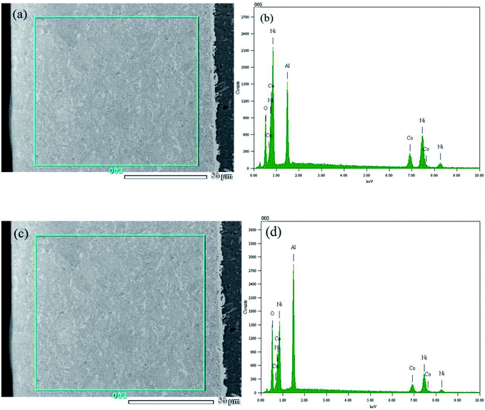
Fig. 2 describes the EDS patterns of the Ni–Co–Al2O3 composite coating prepared by the two processes. Fig. 2 (b) and (d) show that composite coating contains nickel, cobalt, oxygen, aluminum four elements. The result of energy spectrum analysis of composite coating prepared by pulse electrodeposition is shown in Fig. 2(a) and Table 3. As shown in Table 3, the mass fraction of aluminum element is 15.07% and the mass fraction of oxygen is 9.76% in composite coating. The result of energy spectrum analysis of composite coating prepared by electrophoresis–electrodeposition is shown in Fig. 2(c) and Table 4, as shown in Table 4, the mass fraction of aluminum element is 26.53% and the mass fraction of oxygen is 18.6% in composite coating. Therefore, the content of alumina particles in the composite coating prepared by electrophoresis–electrodeposition is much higher than that of pulsed electrodeposition.
 |
| | Fig. 2 EDS micrographs of Ni–Co–Al2O3 composite coating by two different processes. | |
Table 3 Energy spectrum analysis of Ni–Co–Al2O3 composite coatings by pulse electrodeposition
| Element |
(keV) |
Mass% |
Error% |
Atom% |
K |
| O K |
0.525 |
9.76 |
0.05 |
24.92 |
12.8574 |
| Al K |
1.486 |
15.07 |
0.08 |
22.82 |
8.7701 |
| Co K |
6.924 |
18.8 |
0.43 |
13.03 |
19.1025 |
| Ni K |
7.471 |
56.37 |
0.55 |
39.23 |
59.2699 |
| Total |
|
100 |
|
100 |
|
Table 4 Energy spectrum analysis of Ni–Co–Al2O3 composite coating by electrophoresis–electrodeposition
| Element |
(keV) |
Mass% |
Error% |
Atom% |
K |
| O K |
0.525 |
18.6 |
0.06 |
37.75 |
24.8301 |
| Al K |
1.486 |
26.53 |
0.09 |
31.93 |
17.5833 |
| Co K |
6.924 |
13.26 |
0.55 |
7.31 |
13.5675 |
| Ni K |
7.471 |
41.62 |
0.71 |
23.02 |
44.0191 |
| Total |
|
100 |
|
100 |
|
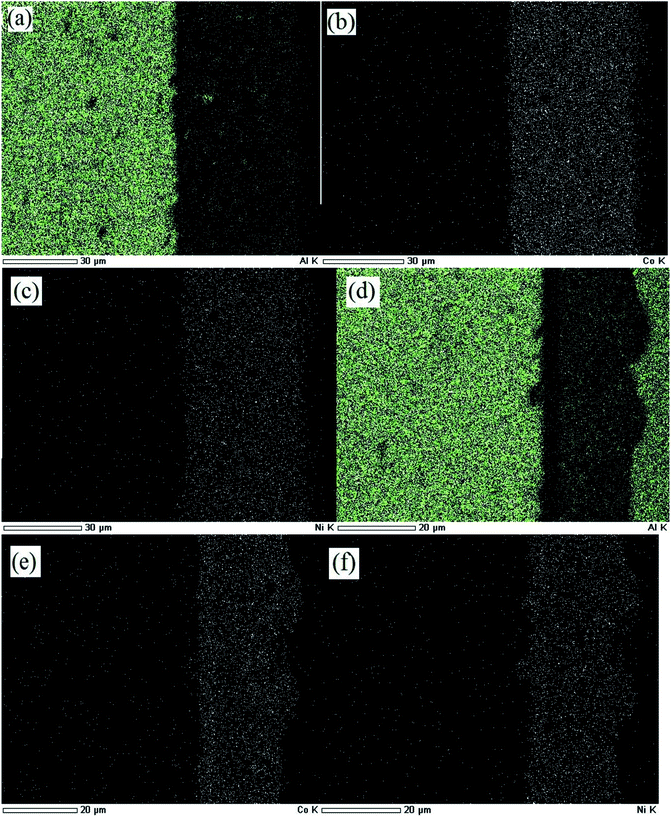
The elemental mapping of Ni–Co–Al2O3 composite coating by the two processes is shown in Fig. 3. Fig. 3 (a)–(c) show elemental mapping of the Ni–Co–Al2O3 composite coating prepared by pulse electrodeposition. Fig. 3 (a)–(c) display the elemental distributions of aluminum, cobalt and nickel respectively. Fig. 3 (d)–(f) show elemental mappings of the Ni–Co–Al2O3 composite coating prepared by electrophoresis–electrodeposition. Fig. 3 (d)–(f) display the elemental distributions of aluminum, cobalt and nickel respectively. It can be seen from Fig. 3(a) and (b) that the aluminum elements are evenly distributed in the layer, meaning that the Al2O3 particles are uniformly dispersed in the layer. Comparing Fig. 3(a) with Fig. 3(d), it can be seen that the content of aluminum in the Fig. 3(d) is significantly higher than in Fig. 3(a). This means that the content of the Al2O3 particles in the composite coating prepared by electrophoresis–electrodeposition is higher than that of the Al2O3 particles in the composite coating by pulse electrodeposition. These conclusions are consistent with those described above.
 |
| | Fig. 3 Elemental mappings of Ni–Co–Al2O3 composite coating by two different processes. | |
3.2 Composition of Ni–Co–Al2O3 composite coatings
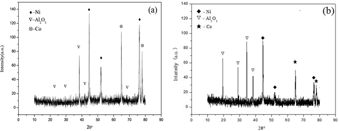
The X-ray diffraction patterns of the Ni–Co–Al2O3 composite coating prepared by the two processes are shown in Fig. 4. Fig. 4(a) shows the X-ray diffraction spectrum of the composite coating prepared by pulsed electrodeposited. The peaks of 2θ = 44.507°, 51.846° and 76.37 in the spectrum could clearly show the characteristic peaks of Ni and the diffraction peak is very sharp. The characteristic peaks of Al2O3 are also found at 2θ = 29.359°, 35.164, 38.155°, 68.212°. The results show that the peak value of alumina in the composite coating prepared by electrophoresis–electrodeposition is higher, which indicates that the content of Al2O3 particles in the Ni–Co–Al2O3 composite coating is higher.
 |
| | Fig. 4 XRD patterns of Ni–Co–Al2O3composite coating by two different processes: (a) pulse-electrodeposition; (b) electrophoresis–electrodeposition. | |
3.3 Microhardness of the Ni–Co–Al2O3 composite coatings
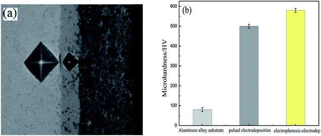
Fig. 5 displays the microhardness of the Ni–Co–Al2O3 composite coating prepared by the electrophoresis–electrodeposition and the pulsed electrodeposition. In order to clearly show the difference of microhardness of different coatings, firstly, a layer of Ni–Co coating was prepared by pulsed electrodeposition on the aluminum alloy substrate for 5 min. Then Ni–Co–Al2O3 coating was prepared by pulsed electrodeposition for 15 min on Ni–Co coating. The third step was to prepare a layer of nano-Al2O3 particles on Ni–Co–Al2O3 coating by means of electrophoretic deposition for 200 s. The nano-Al2O3 particles are easily separated from Ni–Co–Al2O3 coating, so the Ni–Co coating was electrodeposited on it for 10 min. The nano-Al2O3 particles with weak binding force were tightly coated with Ni–Co matrix coating, which with good binding force and high content of nano-Al2O3 particles. Fig. 4(a) shows the microhardness of aluminum alloy matrix, the Ni–Co–Al2O3 composite coating prepared by pulsed electrodeposition and the Ni–Co–Al2O3 composite coating prepared by electrophoresis–electrodeposition. From Fig. 5(a), it can be seen that the indentation of the coating is smaller than that of the substrate, and the indentation has the following tendency: aluminum alloy > pulsed electrodeposition Ni–Co–Al2O3 composite coating > electrophoresis–electrodeposition Ni–Co–Al2O3 composite coating, so Ni–Co–Al2O3 composite coating prepared by electrophoresis–electrodeposition composite process has better hardness. Fig. 5(b) shows the hardness valus of the aluminum alloy matrix, the composite coating prepared by pulsed electrodeposition and the composite coating prepared by electrophoresis–electrodeposition. The microhardness of the Ni–Co–Al2O3 composite coating prepared by the electrophoresis–electrodeposition is about 550 HV, which is significantly higher than that of the pulsed electrodeposition composite coating and the aluminum alloy matrix.
 |
| | Fig. 5 The micro-hardness of Ni–Co–Al2O3 composite coating by two different processes: (a) the creasing of two composite coatings under the same pressure, (b) the microhardness of two composite coatings. | |
The hardness of Ni–Co–Al2O3 composite coating prepared by electrophoresis–electrodeposition is improved significantly, mainly due to fine grain strengthening and dispersion strengthening mechanism. The fine grain metals at room temperature have higher strength, hardness than coarse grain metals. Because the grain is fine, the grain boundary is twists, which is more unfavorable to the expansion of the dislocation. The content of Al2O3 particles of Ni–Co–Al2O3 composite coating is higher, and the coated surface grains are finer.16,17 On the basis of a large number of experiments, a general expression Hall–Petch formula between grain size and metal strength was established
where
σy is the flow stress,
σ0 is the lattice friction,
d is the grain diameter,
K is the constant (positive) associated with the material, and the index
n is always 0.5.
Dispersion strengthening stressed that the second phase with fine particles evenly distributed in the grain of the solid solution, which make the alloyed plasticity, toughness decreased slightly and strength, hardness improved. The Al2O3 particles with high hardness as the second phase of solid particles embedded in the composite coating, and they prevent the movement of the dislocation and lattice deformation. According to the relationship between the dislocation bending stress and the radius of curvature (the following formula 3.2).18 The smaller the particle, the higher the particle content, the smaller the spacing between the particles and the particles make the dislocation bending shear stress large and the dispersion enhancement more obvious. The Ni–Co–Al2O3 composite coating prepared by electrodeposition–electrodeposition contains a large amount of nano-sized alumina particles, which makes the hardness of the composite coating greatly improved under the condition of high dispersion.
| |
 | (3.2) |
where
τ is the shear stress,
G is the shear elastic modulus,
R is the misalignment bending radius, and
λ is the particle spacing.
3.4 Tribological behaviors of the Ni–Co–Al2O3 composite coatings
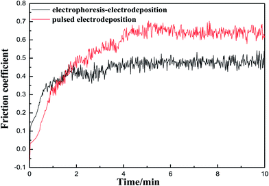
The friction coefficient of the Ni–Co–Al2O3 composite coating prepared by the two processes is shown in Fig. 6. Fig. 6 shows that the friction coefficient of the coating prepared by pulsed electrodeposition is lower than that of the composite coating prepared by electrophoresis–electrodeposition at the beginning of the experiment. With the increase of the experimental time, the friction coefficient of the composite coating prepared by pulsed electrodeposition began to be higher than that of the composite coating prepared by electrophoresis–electrodeposition and was always higher than that of the latter. The reason is that the content of Al2O3 particles in the composite coating prepared by electrophoresis–electrodeposition process is higher than that of the composite coating prepared by pulsed electrodeposition. There is a layer of convex alumina particles on the surface of the composite coating prepared by electrophoresis–electrodeposition. In the initial experiment, the alumina particles are easy to fall off so that the friction coefficient is high. With the surface particles grinded, because the composite coating prepared by electrophoresis–electrodeposition has high hardness and deformation resistance, the friction coefficient changes more slowly. When the friction coefficient reaches about 0.45, the friction coefficient is almost unchanged.
 |
| | Fig. 6 Friction coefficient of Ni–Co–Al2O3 composite coatings by two different processes. | |
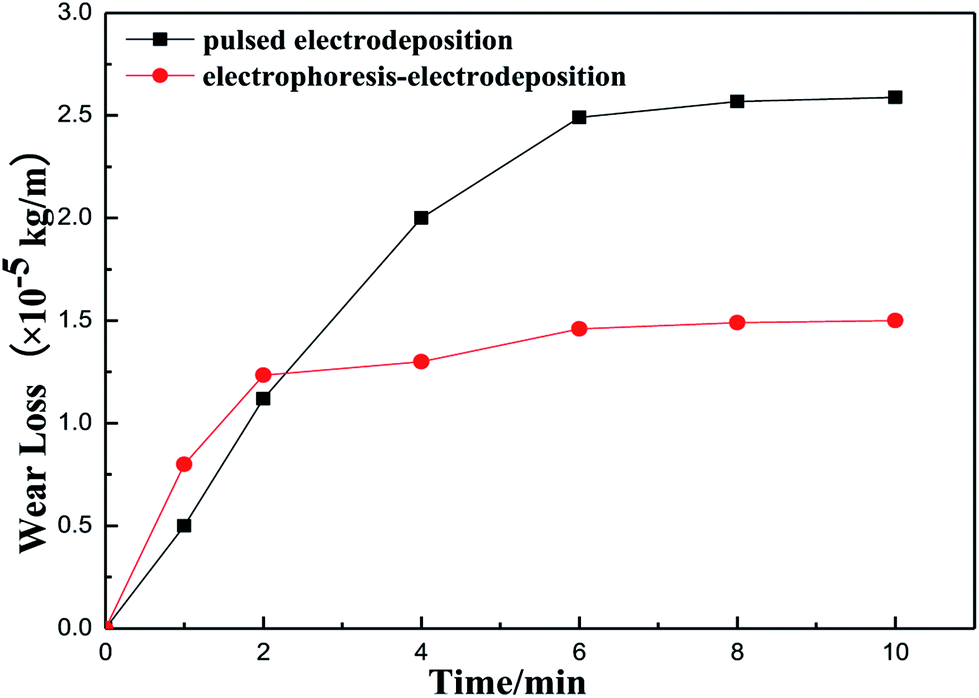
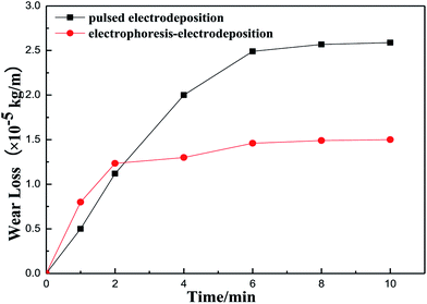
Fig. 7 shows wear loss of Ni–Co–Al2O3 composite coatings prepared by electrophoresis–electrodeposition and pulse electrodeposition with the change of time. The Fig. 7 presents that the wear loss of composite coating compared by electrophoresis–electrodeposition is lower than that of composite coating compared by pulse electrodeposition. As the composite coating compared by the electrophoresis–electrodeposition has a higher content of Al2O3 particles, the alumina particles as the second phase is homogeneously dispersion in the composite coating, which make composite coating has high hardness and strong deformation resistance.
 |
| | Fig. 7 Wear loss of Ni–Co–Al2O3 composite coatings with two different processes. | |
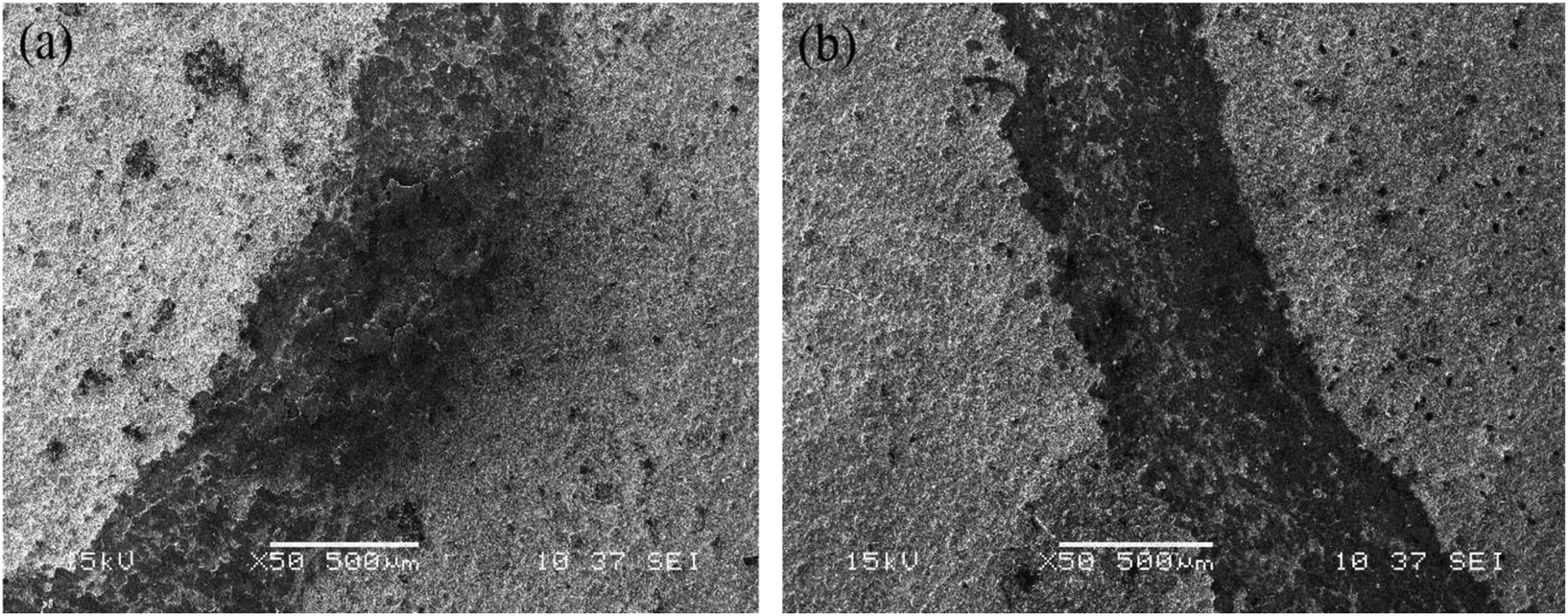
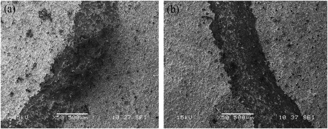
The wear scars of Ni–Co–Al2O3 composite coatings prepared by two kinds of process conditions under the same friction conditions are shown in Fig. 8. Fig. 8(a) shows the wear scars of Ni–Co–Al2O3 composite coating prepared by pulsed electrodeposition. Fig. 8(b) shows the wear scars of Ni–Co–Al2O3 composite coating prepared by electrophoresis–electrodeposition. From Fig. 8(a), it can be seen that some of the area of the coating has been stripped from the substrate and shows a significant grain wear characteristics. From Fig. 8(b), it can be seen that wear surface is relatively smooth, shallow furrow and dose not appear peeling phenomenon, which perform the grain wear characteristics also.
 |
| | Fig. 8 Worn scars of Ni–Co–Al2O3 composite coatings by two processes: (a) pulse electrodeposition, (b) electrophoresis–electrodeposition. | |
The wear resistance of the composite coating is related to the phase structure and composition of the surface. The coating with high strength and high hardness has good wear resistance. As for the Ni–Co–Al2O3 composite coating, the Ni–Co matrix belongs to matrix metal of high hardness, and the nano-Al2O3 particles as the second enhanced phase has a high hardness. During the process of wear and tear, the Ni–Co–Al2O3 composite coating prepared by electrophoresis–electrodeposition did not appear obvious furrow, peeling and other characteristics.19
3.5 Corrosion resistance of the Ni–Co–Al2O3 composite coatings
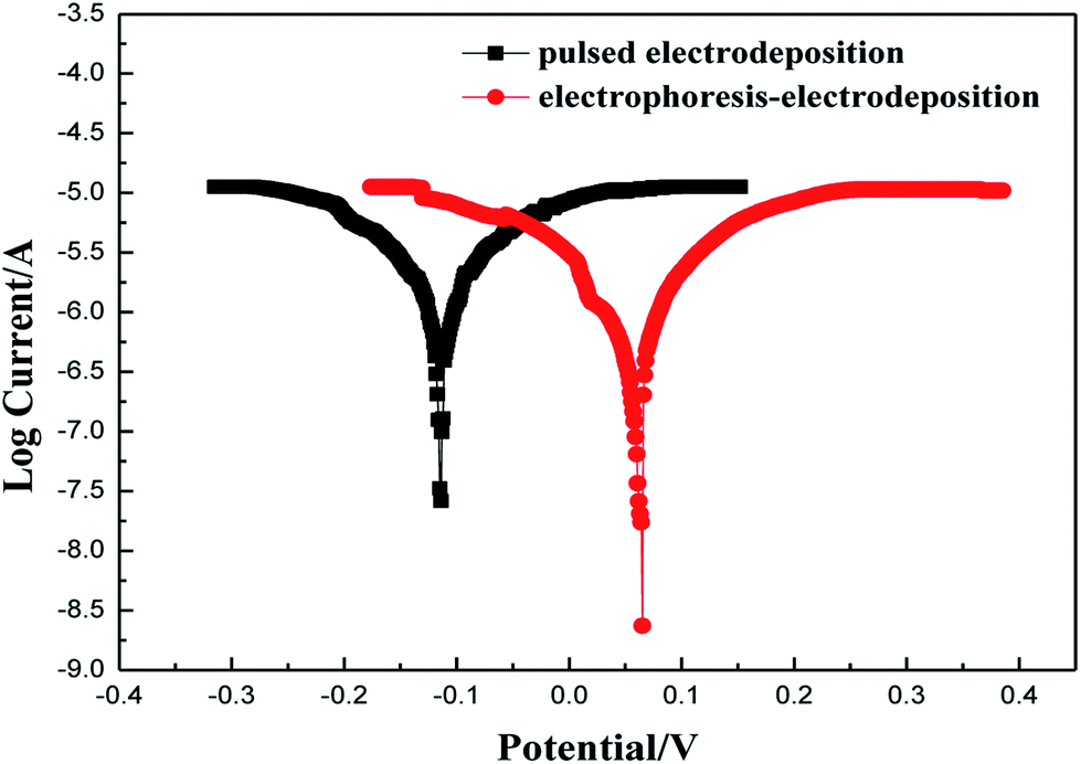
Fig. 9 shows the polarization curves (Tafel curves) of Ni–Co–Al2O3 composite coatings prepared for two different processes, in 3.5 wt% NaCl solution. Fig. 8 shows that the self-corrosion potential of Ni–Co–Al2O3 composite coating prepared by electrophoresis–electrodeposition is +0.065 V, and the self-corrosion potential of Ni–Co–Al2O3 composite coating prepared by pulsed electrodeposition is −0.114 V. It can be described that the corrosion resistance of Ni–Co–Al2O3 composite coating prepared by electrophoresis–electrodeposition is better than that of Ni–Co–Al2O3 composite coating prepared by pulsed electrodeposition. The Al2O3 particles are inert ceramic particles which are not conductive itself, so they play a role in the shield of composite coating and it will reduce the size of the corrosion current. With increasing of Al2O3 particles, this phenomenon is more obvious. The Al2O3 particles hinder the free crystallization of the matrix metal so that the preferential orientation of the single crystal plane occurs in the process of electrical crystallization and the surface potential of the composite coating tends to be homogenization. The micro-chemical uniformity of coating is more excellent, which makes the driving force of the micro-battery of composite coating reduced in the corrosive environment. Therefore corrosion resistance of the composite coating is enhanced. Furthermore, during the growth of the composite coating, the Al2O3 particles make the nucleation rate increasing and the growth rate inhibited.20 This dense composite structure is very useful in suppressing the corrosion dissolution of composite coating.21
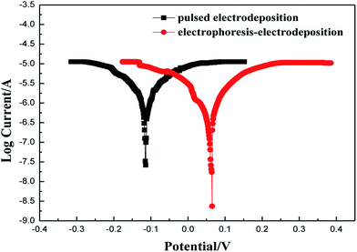 |
| | Fig. 9 The Tafel polarization curves of Ni–Co–Al2O3 composite coatings by two different processes. | |
4. Conclusions
(1) The content of Al2O3 particles of Ni–Co–Al2O3 composite coating prepared by electrophoresis–electrodeposition is higher than that prepared by pulsed electrodeposition.
(2) The hardness of Ni–Co–Al2O3 composite coating prepared by electrophoresis–electrodeposition is higher than that the composite coating prepared by pulse electrodeposition. What is more, the composite coating prepared by electrophoresis–electrodeposition exhibited more excellent wear resistance and low coefficient than the composite coating prepared by pulsed electrodeposition.
(3) The composite coating prepared by electrophoresis–electrodeposition with high Al2O3 content has good corrosion resistance. The Al2O3 particles could improve the corrosion resistance of the composite coating.
Conflicts of interest
There are no conflicts to declare.
Acknowledgements
The work was supported by the National Natural Science Foundation of China (50172023) and the Shaanxi Industrial Science and Technology Research (2014K08-09).
References
- H. Gül, F. Kılıç, S. Aslan, A. Alp and H. Akbulut, Wear, 2009, 267, 976–990 CrossRef.
- C. S. Kumar, S. M. Mayanna, K. N. Mahendra, A. K. Sharma and R. U. Rani, Appl. Surf. Sci., 1999, 151, 280–286 CrossRef CAS.
- A. Hakimizad, K. Raeissi and F. Ashrafizadeh, Surf. Coat. Technol., 2012, 206, 2438–2445 CrossRef CAS.
- J. Yuan, J. Wang and K. Zhang, et al., RSC Adv., 2017, 7(46), 28909–28917 RSC.
- R. K. Saha and T. I. Khan, Surf. Coat. Technol., 2010, 205, 890–895 CrossRef CAS.
- M. Sajjadnejad, A. Mozafari, H. Omidvar and M. Javanbakht, Appl. Surf. Sci., 2014, 300, 1–7 CrossRef CAS.
- L. Chen, L. Wang, Z. Zeng and T. Xu, Surf. Coat. Technol., 2006, 201, 599–605 CrossRef CAS.
- L. M. Chang, M. Z. An, H. F. Guo and S. Y. Shi, Appl. Surf. Sci., 2006, 253, 2132–2137 CrossRef CAS.
- K. H. Hou and Y. C. Chen, Appl. Surf. Sci., 2011, 257, 6340–6346 CrossRef CAS.
- G. Wu, N. Li, D. Zhou and K. Mitsuo, Surf. Coat. Technol., 2004, 176, 157–164 CrossRef CAS.
- S. L. Kuo, Y. C. Chen, M. D. Ger and W. H. Hwu, Mater. Chem. Phys., 2004, 86, 5–10 CrossRef CAS.
- B. Bakhit and A. Akbari, Surf. Coat. Technol., 2012, 206, 4964–4975 CrossRef CAS.
- S. Kishida, D. Y. Ju, H. He and Y. Li, J. Environ. Sci., 2009, 21(suppl. 1), S112–S115 CrossRef.
- G. Song, G. Xu, Y. Quan, Q. Yuan and P. A. Davies, Surf. Coat. Technol., 2016, 286, 268–278 CrossRef CAS.
- E. G. Kalinina, A. A. Efimov and A. P. Safronov, Inorg. Mater., 2016, 52, 1301–1306 CrossRef CAS.
- E. BełtowskaLehman, A. Góral and P. Indyka, Arch. Metall. Mater., 2011, 56, 919–931 Search PubMed.
- S. Mirzamohammadi, H. Khorsand, M. Aliofkhazraei and D. V. Shtansky, Tribol. Int., 2017, 117, 68–77 CrossRef.
- A. F. Zimmerman, D. G. Clark, K. T. Aust and U. Erb, Mater. Lett., 2002, 52, 85–90 CrossRef CAS.
- H. Sharifi, K. Ostovan, M. Tayebi and A. Rajaee, Tribol. Int., 2017, 116, 244–255 CrossRef CAS.
- L. Benea, P. L. Bonora, A. Borello, S. Martelli, F. O. Wenger and P. Ponthiaux, et al., J. Electrochem. Soc., 2001, 148(7), C461 CrossRef CAS.
- B. Szczygieł and M. Kołodziej, Electrochim. Acta, 2005, 50, 4188–4195 CrossRef.
|
| This journal is © The Royal Society of Chemistry 2018 |
Click here to see how this site uses Cookies. View our privacy policy here. 
 Open Access Article
 This Open Access Article is licensed under a Creative Commons Attribution-Non Commercial 3.0 Unported Licence
 ,
Wan-chang Sun*,
Fang Guo,
Ya-ru Dong and
Xiao-jia Liu
,
Wan-chang Sun*,
Fang Guo,
Ya-ru Dong and
Xiao-jia Liu