 Open Access Article
Preparation and anti-oxidation performance of Al2O3-containing TaSi2–MoSi2–borosilicate glass coating on porous SiCO ceramic composites for thermal protection
Xiafei Li,
Junzong Feng*,
Yonggang Jiang,
Hao Lin and
Jian Feng *
*
Science and Technology on Advanced Ceramic Fibers and Composites Laboratory, National University of Defense Technology, 109 De Ya Rd, Changsha, Hunan 410073, P. R. China. E-mail: fengj@nudt.edu.cn; junzongfeng@nudt.edu.cn
First published on 10th April 2018
Abstract
In order to improve the thermal oxidation resistance of carbon fiber-reinforced porous silicon oxycarbide (SiCO) ceramic composites, an Al2O3-containing TaSi2–MoSi2–borosilicate glass coating was formed on the surface of the composites via brushing and sintering. The anti-oxidation property of the coated composites at 1873 K was investigated. Microstructures and chemical compositions of the sample before and after anti-oxidation test were determined using XRD, SEM and EDS. After heating in air at 1873 K for 20 min, the Al2O3-containing TaSi2–MoSi2–borosilicate glass coating effectively protects the SiCO ceramic composites and the coated sample kept its appearance well without obvious defects on the surface. The cross-sectional SEM images show that the coating is covered by a film of oxidation products with a thickness of about 40 μm, which is dense and crack free. Inside the A-TMG coating, irregular-shaped silicides are surrounded by continuous borosilicate glass and no penetrating holes or visible cracks are found. Al2O3 increases the viscosity of the borosilicate glass, which improves oxidation resistance of the coated sample by enhancing gas-penetration resistance of the glass. In contrast, the sample without Al2O3 in the coating slurry is severely oxidized and exhibits lots of open pores on the surface after oxidation test.
1 Introduction
With hypersonic aircrafts reaching the speed of Mach number 10 and above, the temperature of windward surface can rise up to 1873 K correspondingly.1–3 Therefore, this poses a severe challenge to the thermal protection system of the aircrafts, for which thermal protection materials with high temperature resistance, low thermal conductivity, excellent anti-oxidation and anti-ablation performances are urgently required.4,5 Silicon oxycarbide (SiCO) ceramic composites reinforced by hard carbon felts are considered as one of the most promising candidates. It has advantages of rigid thermal insulation, light weight, low thermal conductivity, as well as the ability to retain its strength and shape when exposed to oxidizing environment at above 1873 K because of the extremely high temperature resistance of the hard carbon felts.6–8 However, the porous structure of SiCO ceramic composites causes oxygen to diffuse easily, which significantly weakens the oxidation resistance of the composites and limits its application in oxidizing environment at high temperature.9,10 Therefore, anti-oxidation coating is urgently needed for porous SiCO ceramic composites to prevent degradation.11,12With continuous improvement of the performance of the rigid thermal insulation, the matching surface-thermal-protection coating is also developing. The single-phase glass coating, reaction cured glass coating (RCG), toughened uni-piece fibrous insulation coating (TUFI) and high-efficiency tantalum-based ceramic composite (HETC) have been investigated successively.13 According to the US patents,14,15 the multilayer structure of single-phase glass coating needs to be sintered repeatedly and has a poor thermal shock resistance. RCG is applied on the first generation of rigid thermal insulation (LI). However, the mismatch of the thermal expansion coefficients between the RCG and the substrate has not been completely solved.16–20 TUFI is mainly applied in the second generation of rigid thermal insulation (FRCI and AETB), and the gradient coating has high impact toughness and good thermal shock resistance. However, both RCG and TUFI are SiO2-based coatings, so the utility temperature is limited by the glass yield point.19,21,22 HETC is the latest generation of coating technology, which was applied in the toughened uni-piece fibrous reinforced oxidation-resistant composite (TUFROC) developed by NASA Ames Research Center.23–26 Main components of HETC include TaSi2, MoSi2 and borosilicate glass (B2O3 and SiO2), as well as a small amount of SiB6 as the processing aid. Both TaSi2 and MoSi2 possess high melting points (TaSi2: 2473 K, MoSi2: 2293 K) and low density (TaSi2: 9.14 g cm−3, MoSi2: 6.24 g cm−3). In this coating, they are used as emittance agent. Besides, MoSi2 is also used as an absorbent of oxygen to reduce oxidation rate of TaSi2.27 HETC has a high-emittance and low-catalytic-efficiency surface. Moreover, it shows excellent thermal shock resistance and ablation-resistant characteristics in a heat flux in excess of 300 W cm−2.28–30
Due to successful application of HETC, many researchers have studied the high-emissivity coating.31–35 Tao et al. prepared the TaSi2–MoSi2–borosilicate glass coating on mullite fibrous ceramics to enhance surficial thermal radiation and investigated the effects of TaSi2 dosages on the coating structure, phase composition and thermal shock resistance.36 Shao et al. reported a TaSi2–MoSi2–borosilicate glass coating on fibrous ZrO2 ceramic, whose emissivity is up to 0.9 in the range of 0.3–2.5 μm and exhibited excellent thermal shock resistance.37 Wang et al. introduced 1 wt% Al2O3 whiskers to MoSi2 coating, and significantly improved its oxidation resistance. The mass loss of the coated material was only 0.17% after heating at 1723 K.38 In this paper, Al2O3 was added into the SiO2–B2O3 borosilicate glass to increase its viscosity and the TaSi2–MoSi2–borosilicate glass coating was prepared on the surface of porous carbon-fiber-reinforced SiCO ceramic composites via brushing and sintering method. The gas-penetration resistance of the glass can be enhanced by increasing its viscosity, thus improving anti-oxidation property of the coating and further protecting the substrate effectively. The microstructure, phase compositions of the coating before and after anti-oxidation test at 1873 K in air were investigated.
2 Experimental
2.1 Materials
Methyltirmethoxysilane (MTMS) and methyldimethoxysilane (DMDES) were purchased from Wuhan Yi Hua Cheng Technology Development Co., Ltd., China. Ethanol (EtOH), nitric acid (HNO3) and ammonia (NH4OH) were obtained from Chemical reagent factory of Hunan Normal University. The hard carbon felts were purchased from Hunan Jiuhua Carbon High-Tech Co., Ltd., China, and used as the reinforcement. SiO2, B2O3, Al2O3, TaSi2, MoSi2 and SiB6 powders were all obtained from Sinopharm Chemical Reagent Co., Ltd., China. HNO3 and NH4OH were diluted to 0.1 mol l−1 and 1 mol l−1, respectively, and other chemical reagents were used as received without purification.2.2 Preparation of coating
Porous SiCO ceramic composites with a density of 0.55 g cm−3 and dimensions of 15 mm × 15 mm × 15 mm were used as the substrates and prepared by precursor impregnation and pyrolysis. The precursor used MTMS and DMDES as monomer, EtOH as solvent, HNO3 and NH4OH as catalysts. The prepared composites were hand-polished with 100 grit emery paper before preparing the coatings.It took three steps to prepare the coating sample. First, preparation of borosilicate glass powder: 80 wt% SiO2 powder, 15–20 wt% B2O3 powder and 0–5 wt% Al2O3 powder were ball-milled for 24 h, then placed the mixture in a corundum crucible and heated it in a muffle furnace at 1773 K for 1.5 h. After cooling in the furnace, bulk glass was milled to powders, which were sieved by 300 mesh screen. Second, 40.5 wt% borosilicate glass powder, 50 wt% TaSi2 powder, 7 wt% MoSi2 powder and 2.5 wt% SiB6 powder (as sintering aids) were dispersed in ethanol and ball-milled for 50 h. Third, the coating slurry was coated on the surface of porous SiCO ceramic composites by brushing for certain times, then sintered at 1588 K in air for 10 min. The Al2O3-containing TaSi2–MoSi2–borosilicate glass (A-TMG) coated porous SiCO ceramic composites were obtained.
2.3 Characterizations
The chemical bonds of the borosilicate glass were determined using a Fourier transform infrared (FTIR) spectrometer (Nicolet Avatar-360). The chemical compositions and elemental distribution of the coated sample were determined using X-ray photoelectron spectroscopy (XPS; ESCA LAB250Xi). Oxidation resistance test was carried out in a KBF 1700 furnace. After the furnace was heated up to 1873 K, the coated sample was placed in it and kept for 20 min. The microstructure and element component of the coating before and after oxidation test were analyzed by a JSM-6460 scanning electron microscopy (SEM) and energy dispersive spectroscopy (EDS). The phase compositions of the coating were determined using X-ray diffraction (XRD; D8 Advance).3 Results and discussion
3.1 Microstructure and compositions
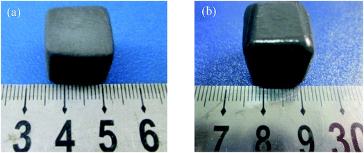
The as-prepared coating shows a good macroscopic appearance without deformation and any cracks on the surface (Fig. 1). Compared with the sample coated by TaSi2–MoSi2–borosilicate glass (TMG), the surface of A-TMG coating is more glossy.To visualize the microstructure of A-TMG coating, the obtained SEM images of the coating surface are shown in Fig. 2a and b. A dense and crack-free surface is observed. Moreover, it can be further seen that the irregular small particles exist as immiscible phases bonded by homogeneous A-TMG phase from the magnification of the coating surface (Fig. 2b). Fig. 2c and d show the cross-sectional SEM images of A-TMG coating, respectively, and the interface between the substrate and the coating is observed therein. The slurry coatings partially infiltrate into the porous structure of the SiCO ceramic composites and are tightly combined with the composites through the continuous glass phase. The coating has a uniform thickness of approximately 180 μm, and no delamination is discovered between the coating and the composites. In the inner coating shown in Fig. 2d, the molten borosilicate glass bonds TaSi2 and MoSi2 particles together while the interior of the coating is not dense.
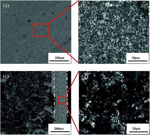 | ||
| Fig. 2 Surface (a and b) and cross-sectional (c and d) SEM images of the A-TMG coating ((b) and (d) are the partial enlarged detail of the red box in (a) and (c), respectively). | ||
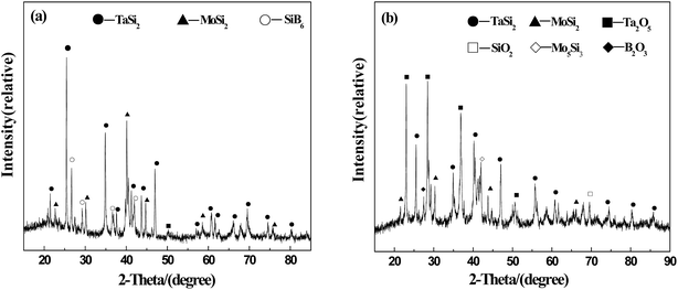
Phase analysis of A-TMG coating is shown in Fig. 3. Inside the coating, the peaks of TaSi2, MoSi2, and SiB6 are detected. In addition, the flat peak at around 22° implies that the A-TMG mainly exists in an amorphous form (Fig. 3a).36 In addition to TaSi2 and MoSi2, Ta2O5, Mo5Si3, B2O3 and SiO2 are also recognized on as-prepared coating surface, whereas the peak of SiB6 disappears in the XRD pattern (Fig. 3b). During the fast sintering process in air, TaSi2 and MoSi2 on the surface are partially oxidized to form Ta2O5 and Mo5Si3. However, the fact that SiB6 tends to be oxidized above 873 K and is completely oxidized at the sintering temperature is not the only reason for producing B2O3 and SiO2. The fact that the borosilicate glass crystallizes during the cooling process should also be responsible for that.32,37,39
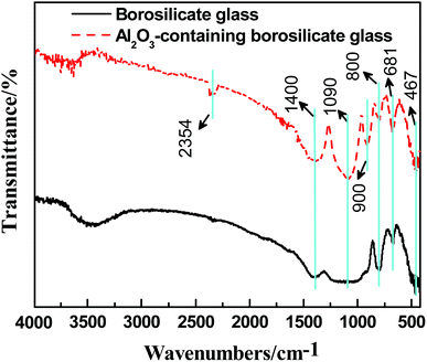
Fig. 4 shows the FTIR spectra of the borosilicate glass with and without Al2O3. The absorption peak at 467 cm−1 is the bending vibration peak of Si–O–Si, and the absorption peak near 800 cm−1 is the stretching vibration peak of O–Si–O. The bending vibration peak of Si–O–Si is near 1090 cm−1, which coincides with the anti-symmetric stretching vibration peak of [BO4]. In addition, the absorption peaks near 681 cm−1 and 1400 cm−1 are bending vibration peak and anti-symmetric stretching vibration peak of [BO3], respectively.40 From Fig. 4, the peaks at 681 cm−1, 1090 cm−1 and 1400 cm−1 of the borosilicate glass with Al2O3 are stronger than that without Al2O3. Theoretically,41 when a small amount of Al2O3 is added into borosilicate glass, Al3+ has priority to capture free oxygen to form [AlO4], entering the lattice structure of SiO2 to make the structure more stable. On the other hand, due to the lack of free oxygen, B3+ mainly exists in the form of [BO3] instead of [BO4]. It can be inferred that the introduction of Al2O3 makes the borosilicate glass denser and increases the glass viscosity at high temperature.
3.2 Anti-oxidation property
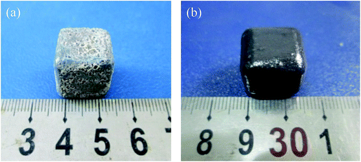
Fig. 5 shows the photographs of the sample after heated in air at 1873 K for 20 min. It can be seen that the TMG coating has poor oxidation resistance at the test temperature. Lots of bulges caused by bubbles burst are overflowed on the coating surface and a large number of white substances are also observed on the coating surface (Fig. 5a). The photograph of the sample coated with A-TMG after oxidation test is presented in Fig. 5b. The sample has a dense and glossy appearance without any cracks. It is believed that the coating can effectively protect porous SiCO composites from oxidation in air at 1873 K after the addition of Al2O3.In our oxidation test, the coating will react with oxygen and the reaction schemes are as follows:27,35,37
| MoSi2 (s) + 7/5 O2 (g) = 1/5 Mo5Si3 (s) + 7/5 SiO2 (s) | (1) |
| TaSi2 (s) + 5/2 O2 (g) = TaO (s) + 2 SiO2 (s) | (2) |
| SiB6 (s) + 11/2 O2 (g) = SiO2 (s) + 3 B2O3 (s) | (3) |
| MoSi2 (s) +7/2 O2 (g) = MoO3 (g) + 2 SiO2 (s) | (4) |
| TaSi2 (s) +13/4 O2 (g) = 1/2 Ta2O5 (s) + 2 SiO2 (s) | (5) |
The XPS element analysis of the white substances in Fig. 5a is shown in Table 1. Theoretically, the contents of Ta and Mo before heated in air are 8.02% and 4.96%, respectively. Supposing that all the TaSi2, MoSi2 and SiB6 are completely oxidized to form solid oxidation products of Ta2O5, Mo5Si3, SiO2 and B2O3,42,43 the contents of Ta and Mo should be 5.30% and 3.31%, respectively. However, since the oxidation time is short, there is only a small amount of silicide being oxidized. Thus, the contents of Ta and Mo should be in the range of 5.30–8.02% and 3.31–4.96%, respectively. From Table 1, the contents of both elements are lower than their theoretical minimum while the contents of Si, O and B are relatively high. Therefore, it can be inferred that the main composition of the white substances may be SiO2–B2O3, which is borosilicate glass.44
| Element | Ta4f | Si2p | C1s:C–O | Mo3d | B1s | O1s |
| Content% | 2.45 | 21.8 | 21.56 | 1.51 | 4.79 | 47.89 |
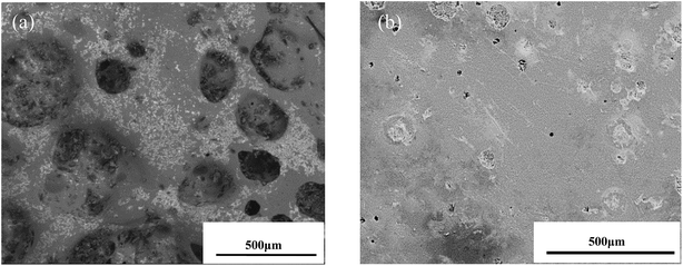
In order to study the microstructure after oxidation test, the surface SEM images of TMG and A-TMG coating after oxidation test are shown in Fig. 6. The TMG coating displays a rough and porous surface with obvious micro defects and holes greater than 200 μm in diameter (Fig. 6a). In contrast, the A-TMG coating surface is smooth with a small number of holes less than 1 μm in diameter (Fig. 6b), indicating that the molten A-TMG coating can fill the microholes and microcracks effectively. Compared with the untested A-TMG coating shown in Fig. 2b, the coating surface becomes denser and more continuous after heated in air at 1873 K, indicating that the formed borosilicate glass heals micro holes by viscous flow.45
Fig. 7a shows the cross-sectional SEM images of TMG coating after oxidation test. Along the cross-section, some areas are dense and have a thickness of about 150 μm, but the substrate is badly oxidized and some pores appear. As shown in the magnified SEM images (Fig. 7b), there are a few of white sheet substances within the coating. According to EDS data (Fig. 7e), the white sheet substances are mainly composed of Si and O, indicating the existence of SiO2.
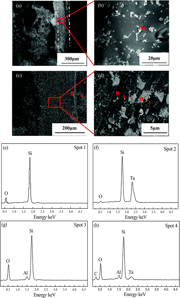 | ||
| Fig. 7 Cross-sectional SEM images of TMG (a and b) and A-TMG (c and d) coating after oxidation test and the corresponding EDS analysis (e–h). | ||
As is shown in Fig. 7c, the A-TMG coating is still dense, intact and well compacted with the substrates. The coating after oxidation is about 230 μm in thickness and no penetrating holes or visible cracks are observed. A film with a thickness of about 40 μm covers the coating surface, which is in different gray level from the interior of the coating. As far as the interior parts of the coating are concerned, white particles in irregular shapes are surrounded by gray continuous phase (Fig. 7d). The following EDS analysis of the irregular white area (Fig. 7f) indicates that the main elements are Si, Ta and a little O, suggesting that it is a mixture of Ta2O5 and non-oxidized TaSi2. The gray continuous phase inside the coating at spot 3 mainly consists of Si, O and Al (Fig. 7g), indicating that it may be molten A-TMG. The reason for the absence of B is that B has a small molecular weight and is difficult to be detected by EDS. The EDS analysis at spot 4 of the surface oxide film (Fig. 7h) shows that the surface comprises Si, Al, Ta and O elements, which suggests that a Ta–Al–Si–O glass layer is generated on the surface of the coating.27 It can be inferred that the oxide film is mainly composed of SiO2, Ta2O5 and TaSi2. Moreover, the oxidation products cover the coating surface very well and form a dense oxidation layer.
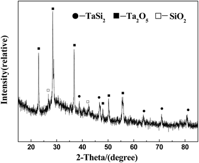
XRD pattern of the A-TMG coating surface after oxidation test is presented in Fig. 8. Besides the TaSi2 phase, Ta2O5 diffraction peak with strong intensity can also be detected, which results from the formation of the oxidation product of TaSi2 based on eqn (5). The appearance of crystalline SiO2 is not only due to oxidation of TaSi2, MoSi2 and SiB6 at high temperature according to eqn (1)–(5), but also due to crystallization of some borosilicate glass during subsequent cooling process.37 Compared to the original XRD pattern of the coating surface (Fig. 3b), the peaks of MoSi2, Mo5Si3 and B2O3 disappear after heated in air at 1873 K for 20 min. The reason for absence of MoSi2 peak is that the amount of MoSi2 is little in the coating slurry so it is completely oxidized at high temperature. Mo5Si3, as the oxidation product of MoSi2, has been further oxidized to generate volatilizable product (MoO3), according to eqn (1) and (4).27 In addition, the absence of B2O3 and Al2O3 peaks may be due to B2O3 evaporation from original borosilicate glass and the low content of Al2O3.46
Fig. 9 shows the failure scheme of the coating at high temperature in air. It is known that the gas inside the porous SiCO ceramic composites tends to expand outside at high temperature. Besides, the complete oxidation of MoSi2 will produce gaseous product, MoO3, which causes pores in the coating. In addition, the coating surface is exposed to air and the oxidation is more serious with an oxide film formed. As we know, the molten borosilicate glass at high temperature has fluidity. Therefore, we believe that the gas penetration resistance of the glass can be enhanced by increasing the glass viscosity through addition of Al2O3. Thus, the silicide in the coating is not easily oxidized and oxidation resistance of the coated sample is improved effectively.
4 Conclusions
A-TMG coating was prepared on the surface of porous carbon fiber reinforced SiCO ceramic composites via brushing and sintering. The coated samples show a good macroscopic appearance without deformation and any cracks. From SEM images, the coating with a uniform thickness of approximately 180 μm partially infiltrated into the porous structure of SiCO ceramic composites and bonded the substrate well. After heated in air at 1873 K for 20 min, the A-TMG coating with a film composed of Al2O3, SiO2 and Ta2O5 covering the surface was still dense and intact. The coating was about 230 μm in thickness and no penetrating holes or visible cracks were found. Compared with the TMG coating, the A-TMG coating had a smoother surface after oxidation test, which indicates that oxidation resistance of the coated sample was greatly improved after addition of Al2O3. The reason may be that addition of Al2O3 increased the viscosity of the borosilicate glass at high temperature, and further prevented the substrates from being oxidized by efficiently enhancing the gas penetration resistance of the glass. Thus, the A-TMG coated porous SiCO ceramic composites with excellent anti-oxidation property are potential thermal protection materials for windward surface of hypersonic aircrafts.Conflicts of interest
There are no conflicts to declare.Acknowledgements
This work is financially supported by National Nature Science Foundation of China (51302317, 51702360) and Natural Science Foundation of Hunan Province (14JJ3008).References
- D. E. Glass, AIAA, 2008-2682.
- C. L. Yan, R. J. Liu, B. L. Zha and C. R. Zhang, J. Alloys Compd., 2018, 739, 955 CrossRef CAS.
- R. T. Voland, L. D. Huebner and C. R. Mcclinton, Acta Astronaut., 2005, 59, 181 CrossRef.
- C. L. Yan, R. J. Liu, Y. B. Cao, C. R. Zhang and D. K. Zhang, Corros. Sci., 2014, 86, 131 CrossRef CAS.
- E. Lee and K. E. Wurster, AIAA, 2017-1146.
- P. Colombo, J. Eur. Ceram. Soc., 2008, 28, 1389 CrossRef CAS.
- H. Tian, Q. S. Ma, Y. Pan and W. D. Liu, Ceram. Int., 2013, 39, 71 CrossRef CAS.
- A. H. Tavakoli, M. M. Armentrout, M. Narisawa and S. Sen, J. Am. Ceram. Soc., 2015, 98, 242 CrossRef CAS.
- T. Takahashi, H. Munstedt, M. Modesti and P. Colombo, J. Eur. Ceram. Soc., 2001, 21, 2821 CrossRef CAS.
- T. H. Xu, Q. S. Ma and Z. H. Chen, Mater. Lett., 2011, 65, 1538 CrossRef CAS.
- L. L. Guo, X. Tao, A. R. Guo and J. C. Liu, Int. Mater. Rev., 2016, 30, 119 Search PubMed.
- L. Bergero, V. M. Sglavo and G. D. Soraru, J. Am. Ceram. Soc., 2005, 88, 3222 CrossRef CAS.
- I. Saleh and R. Raj, J. Power Sources, 2016, 310, 18 CrossRef CAS.
- J. C. Fletcher, A. Pechman and R. M. Beasley, US Pat. 3953646, 1976.
- J. C. Fletcher, A. Pechman and R. M. Beasley, US Pat. 3955034, 1976.
- J. C. Fletcher, H. B. Goldstein and D. B. Leiser, US Pat. 4093771, 1978.
- D. B. Leiser, Ceram. Eng. Sci. Proc., 1981, 809 CAS.
- D. B. Leiser, M. Smith and D. A. Stewart, Ceram. Eng. Sci. Proc., 1983, 551 CAS.
- D. A. Stewart, D. B. Leiser and M. Smith, Ceram. Eng. Sci. Proc., 1983, 533 CAS.
- J. M. Beggs, D. A. Stewart and H. E. Goldstein, US Pat. 4381333, 1983.
- D. B. Leiser, M. Smith and R. A. Churchward, US Pat. 5709082, 1992.
- D. B. Leiser, R. Churchward and V. Katvala, Ceram. Eng. Sci. Proc., 1988, 1125 CAS.
- S. M. Johnson, M. J. Gasch and D. Leiser, AIAA, 2008-2560.
- D. A. Stewart and D. B. Leiser, US Pat. 7314648, 2008.
- D. A. Stewart, D. B. Leiser, AIAA, 2006-7945.
- D. B. Leiser, M. T. S. Hsu and T. S. Chen, US Pat. 6225248, 2001.
- G. F. Shao, X. D. Wu, S. Cui, X. D. Shen, Y. C. Lu, Q. H. Zhang and Y. Kong, J. Alloys Compd., 2017, 690, 63 CrossRef CAS.
- J. P. Wittenauer, S. D. Reeves, K. W. Benner and R. D. Yasukawa, US Pat. 6749942, 2004.
- D. A. Stewart, D. B. Leiser, R. R. DiFiore and V. W. Katvala, US Pat. 7767305B1, 2010.
- C. H. Wang, R. X. Liu and C. L. Zhou, J. Adv. Ceram., 2014, 354, 1763 Search PubMed.
- X. Tao, X. J. Xu, L. L. Guo, W. H. Hong, A. R. Guo, F. Hou and J. C. Liu, Mater. Des., 2016, 103, 144 CrossRef CAS.
- G. F. Shao, X. D. Wu, S. Cui, X. D. Shen, Y. Kong, Y. C. Lu, C. R. Jiao and J. Jian, Ceram. Int., 2016, 42, 8140 CrossRef CAS.
- Q. L. Wen, W. C. Zhou, J. B. Su, Y. C. Qing, F. Luo and D. M. Zhu, J. Alloys Compd., 2016, 666, 359 CrossRef CAS.
- J. F. Huang, Y. L. Zhang, K. J. Zhu, L. Y. Cao, C. Y. Li, L. Zhou, H. B. Ouyang, B. Y. Zhang and W. Hao, J. Alloys Compd., 2015, 633, 317 CrossRef CAS.
- X. Yong, L. Y. Cao, J. F. Huang, W. H. Kong, J. B. Su, C. Y. Li, H. B. Ouyang, L. Zhou and J. T. Liu, Surf. Coat. Technol., 2017, 311, 63 CrossRef CAS.
- X. Tao, X. T. Li, L. L. Guo, X. J. Xu, A. R. Guo, F. Hou and J. C. Liu, Surf. Coat. Technol., 2017, 316, 122 CrossRef CAS.
- G. F. Shao, X. D. Wu, Y. Kong, X. D. Shen, S. Cui, X. Guan, C. R. Jiao and J. Jian, J. Alloys Compd., 2016, 663, 360 CrossRef CAS.
- L. Wang, Q. G. Fu and F. L. Zhao, Intermetallics, 2018, 94, 106 CrossRef CAS.
- X. H. Shi, X. R. Zeng, H. J. Li, Q. G. Fu and J. Z. Zou, Rare Met. Mater. Eng., 2011, 40, 403 CrossRef CAS.
- Z. X. Chen, J. Quan and Y. M. Zhong, J. Wuhan Univ. Technol., 2009, 31, 26 CAS.
- X. Q. Liu, H. E. Feng and Y. Fang, Bull. Chin. Ceram. Soc., 2013, 32, 805 Search PubMed.
- D. S. Hou, K. Z. Li, H. J. Li, Q. G. Fu, Y. L. Zhang and X. T. Li, Rare Met. Mater. Eng., 2009, 38, 252 Search PubMed.
- J. Matsushita and S. Komarneni, Mater. Res. Bull., 2001, 36, 1083 CrossRef CAS.
- G. F. Shao, Y. C. Lu, X. D. Wu, J. Wu, S. Cui, J. Jian and X. D. Shen, Appl. Surf. Sci., 2017, 416, 805 CrossRef CAS.
- X. Tao, X. J. Xu, X. Q. Xu, W. H. Hong, A. R. Guo, F. Hou and J. C. Liu, J. Eur. Ceram. Soc., 2017, 37, 871 CrossRef CAS.
- J. F. Huang, Y. L. Zhang, K. J. Zhu, C. Y. Li, L. Y. Cao, L. Zhou, H. B. Ouyang, B. Y. Zhang, W. Hao and C. Y. Yao, Ceram. Int., 2015, 41, 4662 CrossRef.
| This journal is © The Royal Society of Chemistry 2018 |

