
 Open Access Article
 This Open Access Article is licensed under a Creative Commons Attribution-Non Commercial 3.0 Unported Licence
Nano liquid metal for the preparation of a thermally conductive and electrically insulating material with high stability†
P. Fanab,
Z. Suna,
Y. Wangb,
H. Changab,
P. Zhangb,
S. Yaob,
C. Lub,
W. Rao *bc and
J. Liubcd
*bc and
J. Liubcd
aBeijing Engineering Research Center of Sustainable Energy and Buildings, Beijing University of Civil Engineering and Architecture, Beijing, 100044, China
bBeijing Key Lab of CryoBiomedical Engineering and Key Lab of Cryogenics, Technical Institute of Physics and Chemistry, Chinese Academy of Sciences, 29 Zhongguancun East Road, Haidian District, Beijing, 100190, P. R. China. E-mail: weirao@mail.ipc.ac.cn; Tel: +86-10-82543719
cSchool of Future Technology, University of Chinese Academy of Sciences, Beijing, 100049, China
dDepartment of Biomedical Engineering, Tsinghua University, Beijing, 100084, China
First published on 1st May 2018
Abstract
Dielectric materials typically demonstrate poor thermal conductivity, which limits their application in emerging technologies in integrated circuits, computer chips, light-emitting diode lamps, and other electronic packaging areas. Using liquid metal microdroplets as inclusions to develop thermal interface materials has been shown to effectively improve thermal pathways, but this type of material may become electroconductive with the application of a concentrated compressive stress. In this study, an isotropic nano-liquid metal thermally-conductive and electrically-insulating material (nLM-THEM) is developed by combining a modified polymer and well-dispersed nanoparticles, achieving an ∼50× increase in thermal conductivity over the base polymer. In addition, the thermal conductivity of nLM-THEMs exhibits no significant change with varying humidity and a stable anti-corrosion effect even in direct contact with aluminum. More importantly, nLM-THEMs demonstrate a stable electrical insulating property upon compressive stress, while conventional micro-LM-THEMs exude liquid metal. This exceptional combination of thermal and electrical insulation properties is enabled by the interconnection of uniform and spherical liquid metal nanoparticles to create more thermally-conductive pathways, and surfactant modified nanoparticles ensure excellent electric insulation. Moreover, this material can achieve passive heat exchange through rapid heat dissipation, which demonstrates its great application potential in the electronic packaging area.
1 Introduction
With electronic products advancing to applications in artificial intelligence and miniaturization, a high degree of integration and power density is necessary for these devices. Heat dissipation in these devices has a great impact on their performance and reliability, where a rise of 2 °C in the electrical components will reduce the device reliability by 10%.1–4 Therefore, heat dissipation is key to developing high-performance electronic products of the future. The development of thermally-conductive and electrically-insulating materials (THEMs) is an effective way to solve the problem.5The thermal conductivity of conventional THEMs is mainly based on an organic silica gel incorporating metal oxide and/or metal nitride fillers such as alumina, zinc oxide, magnesium oxide, bismuth oxide, silicon nitride, boron nitride, aluminum nitride and silicon carbide, which operate as conductive inclusions. The thermal conductivity of these THEMs ranges from 0.5 to 5 W m−1 °C−1,6–18 but the heat conduction of these types of THEMs is limited owing in part to the ease with which the THEMs absorb moisture and deteriorate in the open air. To improve the thermal capacity of THEMs, solid particle fillers of gold, silver, copper, aluminum, magnesium and other metals have been investigated.19–22 For polymer-based THEMs, the contact area between the thermally-conductive fillers and the polymer increases as the proportion of the inclusions increases. Consequently, the filling particles disperse in the matrix and form a relatively stable and efficient heat transfer path owing to their direct contact with the polymer, where the path is called a thermally-conductive mesh chain.23–30 These excellent heat transfer paths effectively improve the thermal conductivity of the composite material, but it is not feasible to continuously increase the composite thermal conductivity with the unrestricted addition of thermally-conductive fillers. For example, the most common thermal filler is a solid powder and when the filling ratio reaches a threshold value the composite material is easily dried. Further, composite materials that use metal powders as fillers exhibit a significant reduction in its electrical resistance.31
Unlike the traditional solid filler, a room-temperature liquid metal (LM) has a broad applicability for thermal management, and especially the gallium indium eutectic alloy (EGaIn) with a higher thermal conductivity and volume heat capacity. In 2013, Liu et al. developed a thermal interface material (TIM) with a thermal conductivity of 13.07 W m−1 K−1 based on liquid gallium-based materials and oxidation processes.32 However, this kind of LM-TIM also possesses high electrical conductivity and has a serious corrosion effect on aluminum alloys, and is therefore not applicable for electronic devices. In 2014, Mei et al. prepared a composite thermal grease comprising a gallium alloy as a thermal filler and methyl silicone oil as a matrix, whose maximum thermal conductivity was 5.27 W m−1 K−1.33 But the risk of leakage still exists. In addition, LM microdroplets instead of solid metal particles can provide the liquid filler for high-performance THEMs. For example, Bartlett et al. have used LM droplets as fillers in a silicone elastomer to obtain a flexible composite material whose thermal conductivity was 4.7 ± 0.2 W m−1 K−1 under stress-free conditions and 9.8 ± 0.8 W m−1 K−1 at 400% strain,34 and that is to say the high thermal conductivity of the composite material is not isotropic, it is only along the direction of the elongated droplets. These LM-based THEMs dramatically enhanced the thermal management in electronic packaging applications.
Currently, most LM-based THEMs consist of microscale LM droplets as inclusions, but it has been found that this type of LM-filled composite thermal material runs the risk of electrical leakage. Specifically, when the thickness of the coating layer is reduced the LM will precipitate under a light pressure load. In addition, silicone oil leakage may occur during storage after a period of time. These problems restrict the further development and application of LM-based THEMs, and thus it is particularly urgent and necessary to solve the problem of the THEM stability.
Here, we propose the use of a modified polymer subjected to ultrasonic dispersion to improve the surface treatment of the LM. A high-stability THEM based on a nano-liquid metal (nLM) was prepared, where the THEMs exhibited high thermal conductivity and insulation characteristics in all directions (i.e. isotropic) as well as excellent stability. This method solves the stability problem of the binary dispersion system as well as the silicone oil exudation problem. Furthermore, it prevents the risk of electrical leakage or corrosion risk brought about by the metal precipitation. Highly-stable nLM-THEMs exhibit great potential in electronic cooling systems.
2 Experimental section
2.1 Materials
The gallium (purity: >99.99%) and indium (purity: >99.995%) were purchased from Zhaofeng Gallium Co., Ltd. (Yangquan, Shanxi, China) and Yilong Hung Industrial Co., Ltd. (Zhuzhou, Hunan, China), respectively. Silicon oil was obtained from Xilong Chemical Co., Ltd. (Shantou, Guangdong, China), anhydrous ethanol (analytical grade) was purchased from Beijing Chemical Works (Beijing, China), and the sorbitan trioleate surfactant Span®85 (analytical grade) was obtained from Sigma-Aldrich (St. Louis, MO, USA).2.2 Synthesis of nLM-THEMs
Span 85 (0.8 ml) was added to anhydrous ethanol, where upon the mixed solution was heated to 60 °C and stirred for 5–10 min. Then, EGaIn (24 ml) was added to the mixed solution under sonication with a Branson 550 digital sonifier (Danbury, CT, USA), samples under different sonication time and power were compared. A certain volume of the resultant LM solution (VLM) was then added to different volumes of methyl silicone oil (VMSO) such that VLM![[thin space (1/6-em)]](https://www.rsc.org/images/entities/char_2009.gif) :VMSO = 3:1, 4:1, 5:1 and 6:1. The mixture was heated to 60 °C to remove the anhydrous ethanol and was continuously stirred to form a homogeneous paste. When the vast majority of the anhydrous ethanol was evaporated, as determined by the change of the volume of the mixture, the paste was cooled to room temperature and evacuated in a vacuum oven for 1 h to remove the bubbles present in the sample. After completing the above steps, a thermal-interface material based on an nLM was obtained.
:VMSO = 3:1, 4:1, 5:1 and 6:1. The mixture was heated to 60 °C to remove the anhydrous ethanol and was continuously stirred to form a homogeneous paste. When the vast majority of the anhydrous ethanol was evaporated, as determined by the change of the volume of the mixture, the paste was cooled to room temperature and evacuated in a vacuum oven for 1 h to remove the bubbles present in the sample. After completing the above steps, a thermal-interface material based on an nLM was obtained.
2.3 Characterization of nLM-THEMs
The size and morphology of the resultant nanomaterials were obtained using scanning electron microscopy (SEM; QUANTA FEG 250, FEI, Hillsboro, OR, USA) images. The SEM samples were prepared by placing the dry nLM-THEMs on a freshly black conductive adhesive and the experiments were performed at room temperature.Thermal conductivity and heat capacity measurements of the nLM-THEMs were performed in air using a computer-controlled Hot Disk thermal constants analyzer (K-analys AB, Sweden) with a disk-type Kapton sensor 5465 with radius 3.189 mm in the range of 150–500 mW. Prior to each measurement, the sample was placed into a thermostat-controlled furnace (25 °C) for 1 h.
To study the electrical insulation characteristics of the nLM-THEMs, the electric resistivity measurement was conducted using a meg-ohm test system comprising an electrode protection test box and a high electrical-resistance meter (HPS68004, HELPASS, China). The test voltage range was set from 5 to 220 V.
2.4 Anticorrosion evaluation
To quantify the anticorrosion effects of the nLM-THEMs on an aluminum block, following the corrosion tests the aluminum block surface was observed using a field-emission-gun SEM (FEG-SEM; Sirion 200, FEI, Hillsboro, OR, USA), and energy-dispersive X-ray analysis (EDX) was simultaneously performed.2.5 Comparison of heat distribution
To test the cooling effect characteristics of the THEMs, a commercial methyl silicone oil (201) and Deepcool Z9 thermal conductive paste possessing a thermal conductivity greater than 4.0 W m−1 K−1 were used in a parallel experiment alongside then LM-THEMs with an LM volume fraction of 85.7% (v/v). The silicone oil, commercial thermal conductive paste and the nLM-THEMs were coated on the surface of a heat shield in patches 30 mm (length) × 30 mm (width) × 3 mm (height) in size, whereupon three heating chips with the dimensions 7 mm × 5 mm were placed in the center of the coated patches of each of the three types of THEMs. A thermocouple was then arranged at the center of the heating chip, and a data acquisition instrument (Agilent 34972A, USA) was used to collect the real-time temperature. In addition, an infrared thermograph (FLIR E30, USA) was applied to obtain the two-dimensional temperature distribution. The input voltage of the heating chip was set at 3 V and heating commenced for 10 min.3 Results and discussion
3.1 Formation of nLM particles
The EGaIn comprising 75.5% (w/v) gallium and 24.5% (w/v) indium is a nLM at room temperature, and has excellent thermal conductivity suitable for making high-thermal-conductivity THEMs. In the experiment, a nLM-THEM was prepared using EGaIn as the thermally-conductive filler and 201-methyl silicone oil as the matrix material, which were combined via ultrasonic mixing and the addition of Span 85. The preparation process is shown in Scheme 1.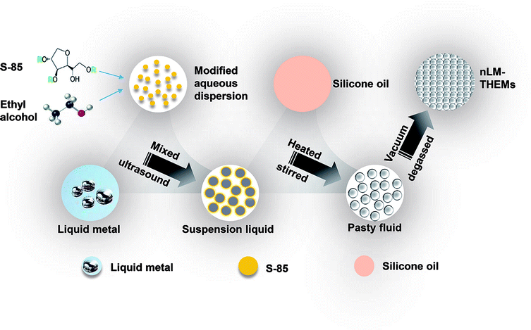 | ||
| Scheme 1 Schematic diagram of the nLM-THEM fabrication process. | ||
It is worth noting that the important parameters affecting the size of nLM are sonication time and sonication power.35 To determine the appropriate time and power of sonication, a batch of experiments is performed and the results is shown in Fig. S1(a) and (b),† respectively. With the increase of sonication power (sonication time is 25 min), the average size of liquid metal nanoparticles decreased first, then increased, and finally stabilized (Fig. S1(a)†). When the sonication power is 300 W, the average size of nanoparticles reaches the minimum (259.1 nm); Fig. S1(b)† shows the average size change with sonication time under certain power (P = 280 W), the size of liquid metal nanoparticles first descends, then increases, and gradually stabilizes. When the sonication time is 40 min, the average particle size reaches a minimum of 248.1 nm. Based on the experimental results, 300 W and 40 min is chosen to make liquid metal nanoparticles, dynamic light scattering (DLS) measurement of the nanoparticles is shown in Fig. S1(c).† The average size of nLM is 232.5 nm. The smaller the size of nLM, more contact with 201-methyl silicone oil will be achieved with the same weight of nLM as filler. Therefore, 300 W and 40 min is chosen for the nLM-THEMs preparation and the next experiments.
Four kinds of nLM-THEMs with different filling ratios were prepared by the above process, where the volume proportions of the LM (VLM) and that of methyl silicone oil (VMSO) were VLM:VMSO = 3:1, 4:1, 5:1, 6:1 (volume fractions of LM is 75.0%, 80.0%, 83.3% and 85.7%, respectively). The microstructures of these four variations of nLM-THEMs are shown in Fig. S2† and a typical example of the nLM-THEM (VLM:VMSO = 6:1) is shown in Fig. 1(a) and (b). According to the SEM images, the nLM-THEMs are a dense array of smooth spherical particles mostly ranging from 100–800 nm in diameter at 22 °C (Fig. S3†), which is consistent with DLS data (Fig. S1(c)†). The reason why the uniformity is not ideal is that all the products after LM sonication are collected, if gravity settling and stratified centrifugation of nLM sample can be properly conducted, the uniformity of nLM-THEMs will be further improved. Even though, compared to the microstructure of a micro-LM-TIM prepared by the conventional process (see Fig. 1(c) and (d)), it demonstrates that the droplet diameter of micro-LM THEMs is between 10–200 μm, and the shape of the LM droplets is irregular and nonspherical, showing worse uniformity.
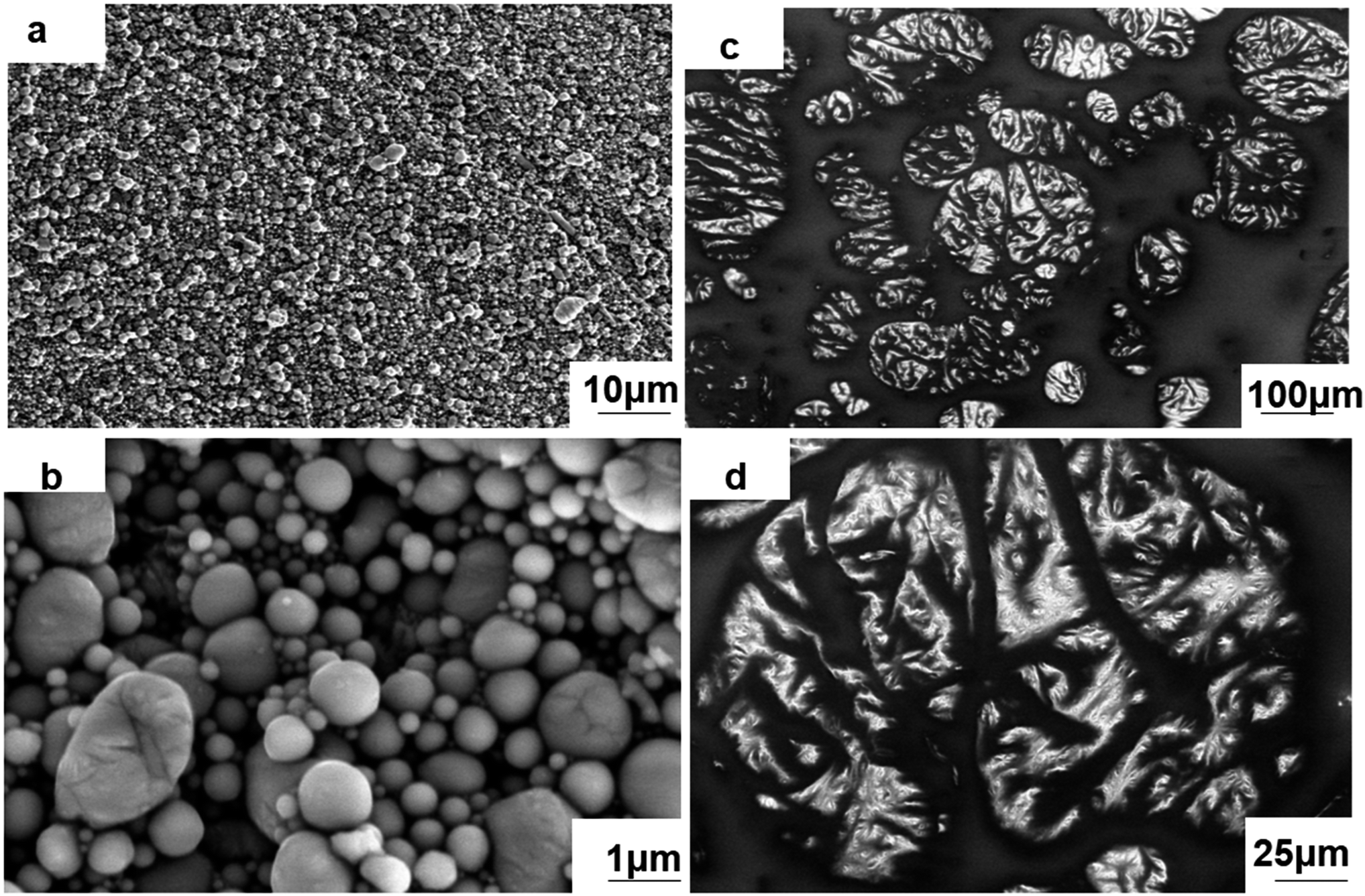 | ||
| Fig. 1 SEM images of the THEMs. Microscopic morphology of the (a) and (b) nLM-THEMs and (c) and (d) micro-LM THEMs. | ||
3.2 High thermal conductivity and electrical insulation with nLM-based material
Thermal conductivity is the most important physical parameter for measuring the heat dissipation effect of the THEMs. The thermal conductivities of the nLM-THEMs with different volume fractions 75.0%, 80.0%, 83.3% and 85.7% are measured as 4.03 ± 0.01, 4.40 ± 0.02, 4.92 ± 0.01 and 6.73 ± 0.04 W m−1 K−1, respectively, as shown in Fig. 2(a). As the LM volume fraction in the TIM increases, the thermal conductivity of the TIM also increases, though it does not exhibit a linear trend with the LM filling ratio. An increasing proportion of LM nanoparticles will form more thermal conduction paths because of more frequent contact among these particles. It is worth noting that thermal conductivity cannot increase in an unlimited fashion by increasing the LM volume fraction because the modified LM nanoparticles will reach a saturated state in the silicone oil when the LM fraction is greater than 87.5%. This saturated state leads to the propensity of the TIMs to dry and a significant reduction in the electrical insulation.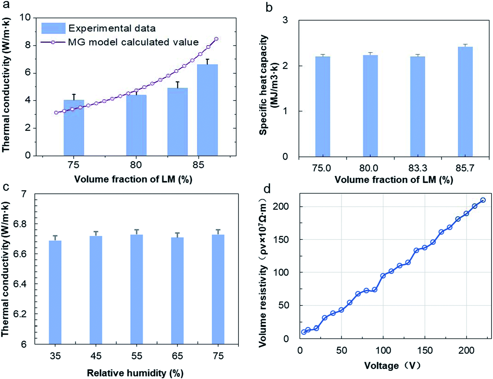 | ||
| Fig. 2 Physical characterization of the nLM-THEMs. (a) Thermal conductivities of the nLM-THEMs containing varying LM volume fractions showing well consistency with MG model prediction. (b) Specific heat capacities of the nLM-THEMs varying LM volume fractions showing no significant difference. (c) Thermal conductivities of the nLM-THEMs at varying humidity levels. (d) Electrical resistivity of the nLM-THEMs. | ||
The thermal conductivity of the binary composites can be predicted using the theoretical Maxwell-Garnett's (MG) model,36 which is quite commonly used as an effective medium theory to predict the thermal conductivity of binary mixtures. The MG model can be given as follows:
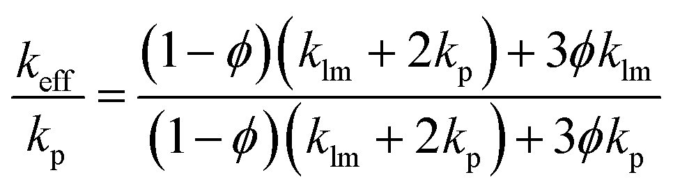 | (1) |
The specific heat capacity represents the ability of an object to absorb or dissipate heat. At the same heat absorption, the temperature of an object with a higher specific heat capacity will be lower. Thus, the size of the heat capacity can also reflect the intensity of the THEM thermal conductivity. The specific heat capacity of the nLM-THEMs with different LM volume fractions 75.0%, 80.0%, 83.3% and 85.7% are measured as 2.20 ± 0.05, 2.24 ± 0.03, 2.20 ± 0.08 and 2.42 ± 0.08 MJ m−3 K−1, respectively, as shown in Fig. 2(b). From these experimental results it is clear that, though nLM-THEMs have a high specific heat capacity, increasing of the volume fraction of LM does not significantly change the specific heat capacity.
Many types of THEMs degenerate quickly when exposed to the open air, wherein the relative humidity of the air has a great impact on the material properties. Under conditions that were otherwise identical, the thermal conductivity of the nLM-THEM (LM fraction is 85.7%) was tested at different humidity levels. Fig. 2(c) shows the results of the thermal conductivities of the nLM-THEMs of 6.69 ± 0.02, 6.72 ± 0.02, 6.73 ± 0.04, 6.71 ± 0.01 and 6.73 ± 0.03 W m−1 K−1 for relative humidity levels of 35, 45, 55, 65 and 75%, respectively. It is demonstrated that the thermal conductivity of the nLM-THEMs remained essentially unchanged with varying relative humidity. This demonstrates that the heat dissipation effect of the nLM-THEMs is nearly unaffected in different indoor environments, which further proves the high stability of nLM-THEMs.
To verify the insulation properties of the nLM-THEMs, we measured their volume resistivity at different voltages in the range of 5–220 V, as shown in Fig. 2(d). It can be seen that the volume resistivity–voltage curve is approximately a straight line, indicating that the volume resistivity of the nLM-THEMs is closely related to the applied electric field. With the increase of the measured voltage, the resistivity of the TIM also increases. The volume resistivity is 9.8 × 10⁷ Ω m when the measured voltage is 5 V, and the volume resistivity is 2.09 × 10⁹ Ω m when the measured voltage is 220 V. As shown in Fig. 2(a)–(d), we can see that the nLM-THEM has excellent thermal conductivity and electrical insulating properties.
3.3 Enhanced stability of nLM-THEMs compared to micro-LM THEMs
To further test the stability of nLM-THEMs, a series of experiments were conducted. First, nLM-THEMs were placed at room temperature for a month. As shown in Fig. 3(a), the morphology of the nLM-THEMs stored in a glass bottle is stable with no apparent change. For comparison, the same proportion of micro-type THEMs (micro-LM-THEMs) was prepared according to the traditional process,33 and the results are shown in Fig. 3(b). It can be seen that the upper surface of the conventional micro-LM-THEMs in the glass bottle gradually exudes silicone oil with time, and the accumulation of a silicone oil top layer is obvious after a month.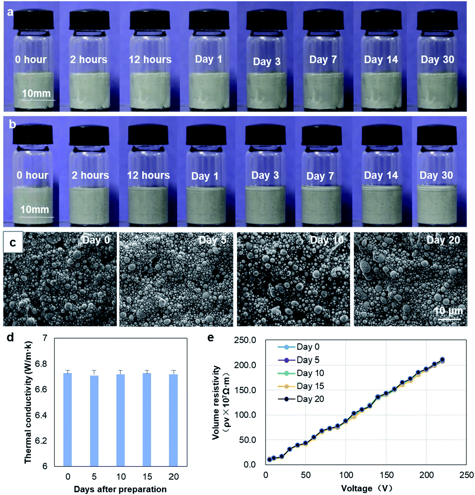 | ||
| Fig. 3 Stability of nLM-THEMs. (a) and (b) Changing state of (a) nLM-THEMs and (b) conventional micro-LM-THEMs after resting for various durations at room temperature. (c) Microscopic morphology of nLM-THEMs showing no apparent difference from day 0 to day 20. (d) Thermal conductivity of nLM-THEMs showing no significant difference along the exposing time. (e) Electric resistivity of nLM-THEMs showing no significant difference along the exposing time. | ||
Further SEM characterization of nLM-THEMs was conducted after preparation for different days. As shown in Fig. 3(c), the diameter of liquid metal particles was about several hundred nanometers after preparation. The observation was conducted on day 0, day 5, day 10 and day 20, respectively. It was demonstrated that the size and distribution of liquid metal particles in the same nLM-THEMs sample was almost indistinguishable with time, and no aggregation formed in the sample. In addition, the changes in thermal conductivity and electric resistivity of the nLM-THEMs were also measured every 5 days after the material fabrication, the results were shown in Fig. 3(d) and (e). It was found that the thermal conductivity and electrical resistivity of the materials showed no significant difference with time. Both the thermal and electric characterization together with morphology show that the nLM-THEMs is remarkably stable along the exposing time.
To demonstrate the contact stability of the nLM-THEMs with various substrates, three different material plates of glass, plastic and copper were used for nLM-THEM-coating experiments. The thickness of the coating in the experiment is about 0.1 mm, which is similar to the thickness of ordinary A4 paper, and is shown in Fig. 4(a). The coating surface appears gray and delicate, and exhibits no LM precipitation. After one month, no significant changes were observed on the coating surface or at the edge of the coating material (see Fig. 4(b)). In contrast, when a conventional LM-TIM was coated on cardboard with a similar coating thickness, LM precipitation could be observed, as shown in Fig. 4(c). This demonstrates that the nLM-THEM is more stable and coats the substrate easier, which exhibits superior practical application advantages compared to conventional LM THEMs.
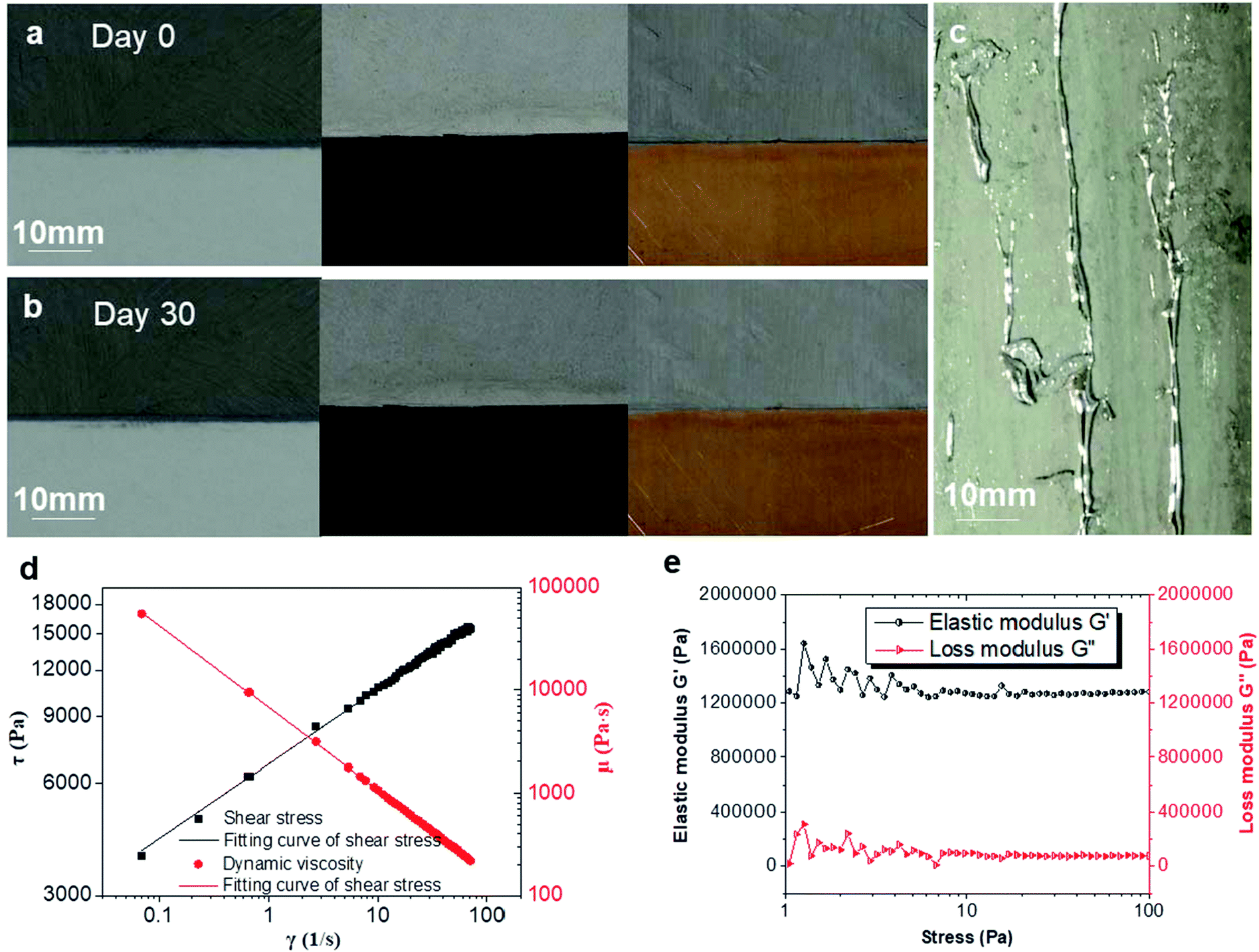 | ||
| Fig. 4 nLM-THEMs showing high adhesivity and stability to various substrates. (a) and (b) State of a thin layer of nLM-THEMs on surfaces composed of (from left to right) glass, plastic and copper plates (a) directly after being coated and (b) a month after being coated. (c) Cardboard coated with a thin layer of micro-LM-THEMs exhibiting LM microdroplets that have fused into macrodroplets. (d) Rheological properties of the nLM-THEM. (e) Viscoelastic plots of nLM-THEM. | ||
The reason why nLM-THEMs showing high adhesivity and stability to various substrates was further conducted. We measured the rheological properties of the nLM-THEMs, using the rotational rheometer (Haake RS6000, Thermo Fisher Scientific Inc., MA, USA). From the relation among shear rate, dynamic viscosity and shear stress (Fig. 4(d)), the nLM-THEMs should belong to non-Newtonian fluid, thus shear thinning occurs. And its rheological properties seem to be the same as that of power law fluid, because of the linear γ–τ relationship with logarithmic coordinates. Moreover, the dynamic viscosity of nLM-THEMs is limited between 100 Pa s to 100000 Pa s with shear rate ranging from 0.1 s−1 to 100 s−1, therefore, it could be easily coated on the various surface of heat source easily, which is consistent with the above experiments (Fig. 4(a) and (b)). During the study of the rheological properties of nLM-THEM, to ensure that nLM-THEM materials are within the range of linear viscoelasticity, stress scan of nLM-THEM was performed. nLM-THEM exhibits linear viscoelasticity under stress range from 8 Pa to 100 Pa (Fig. 4(e)). According to the results, the elastic modulus of nLM-THEM is much larger than the loss modulus, demonstrating that nLM-THEM mainly undergoes elastic deformation under stress.
3.4 Anticorrosion effect of nLM-THEMs
As we know, THEMs are used widely in chip cooling systems and are in close contact with the chips packaging material which usually is made of aluminium silicon alloy, signifying that corrosion resistance of aluminium is critical to ensure the safety of the chips. When aluminum reacts with oxygen, an oxide film is generated on the surface that impedes further reaction of the aluminum with oxygen. However, gallium-based alloys cause the aluminum atoms to react with oxygen molecules in the air by atomic migration, which generates much alumina and causes aluminum plate corrosion.37 To demonstrate the anticorrosion characteristics of the nLM-THEMs, EGaIn and nLM-THEMs were designed to corrode a piece of aluminum.Two pieces of aluminum (40 mm × 40 mm × 20 mm) were polished to remove the surface oxide layer, and EGaIn and EGaIn nLM-THEMs were subsequently applied uniformly on the surface of the aluminum in separate areas. Images were recorded daily for nine days, and the results are shown in Fig. 5(a) and 4(i).
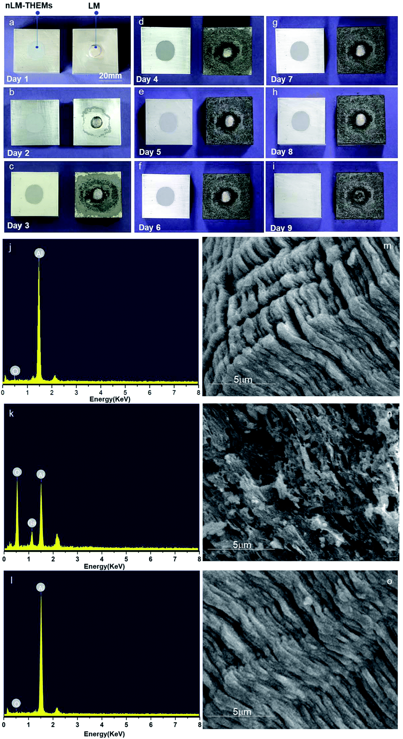 | ||
| Fig. 5 Corrosion test results. (a)–(i) Corrosion of aluminum surface as a function of time. (j) Energy-dispersive spectra of the clean aluminum blocks. (k)–(l) Energy-dispersive spectra of aluminum blocks after nine days of contact with (k) micro-LM-THEMs and (l) nLM-THEMs. (m) FEG-SEM image of the clean aluminum surface. (n) and (o) FEG-SEM image of the aluminum surface after nine days of contact with (n) micro-LM-THEMs and (o) nLM-THEMs. | ||
It can be seen that aluminum coated with EGaIn corrodes completely, while aluminum coated with the nLM-THEMs remains as bright and clean as the original surface. The FEG-SEM images and EDX spectra further demonstrate the anticorrosive effect of the nLM-THEMs. According to the EDX spectrum analysis, the ratio of oxygen and gallium increases and the aluminum is relatively reduced when the aluminum block is in contact with EGaIn (Fig. 5(k)) compared to the clean aluminum (Fig. 5(j)) and the elemental composition of the aluminum in contact with nLM-THEM (Fig. 5(l)) does not change during the corrosion test. After the aluminum is in contact with EGaIn, the aluminum surface becomes porous and uneven (Fig. 5(n)). In contrast, the structure of aluminum in contact with nLM-THEM exhibits a regular and close arrangement with no corrosion (Fig. 5(o)) as well as the clean aluminum (Fig. 5(m)).
Before the XRD/EDS analysis, the nLM-THEMs was removed by plastic scraper, then the aluminum plate was gently wiped cleanly with dust-free paper. In order to test whether there is corrosion existed in the nLM-THEMs sample, we further analyzed the scraped nLM-THEMs from the aluminum plate by energy spectrum, and the result is shown in Fig. S4.† From the element content table and the spectrum analysis, it is found elements containing C, O, In, Ga and Si, except Al. Hence, it is strongly proved that the aluminum corrosion hasn't been occurred when contact with nLM-THEMs.
The LM nanoparticles in the nLM-THEM form an effective protective layer after modification to prevent direct contact between the LM and the aluminum surface, thus avoiding further corrosion by blocking the migration of gallium atoms. In addition, the nLM-THEM demonstrates no obvious corrosion response to the glass, plastic or copper plates, as shown in Fig. 4(c) and (d). In summary, the nLM-THEMs have excellent thermal insulation properties and stability, as well as good corrosion resistance.
3.5 Enhanced cooling effect of nLM-THEMs
To demonstrate the actual heat dissipation effect of the nLM-THEMs, 201-methyl silicone oil, Deepcool®Z9 thermal conductive grease with thermal conductivity > 4.0 W m−1 K−1, and nLM-THEMs with a volume fraction of LM of 85.7% (v/v) are used to do a parallel test of the cooling effect. Fig. 6(a) shows a schematic diagram of the experimental device. The stability of the thermal distribution is shown in Fig. 6(b), where it can be seen that the average temperature of the device with the silicone oil as the interface material is highest, the average temperature with Deepcool Z9 is lower, and the average temperature with nLM-THEMs is lowest.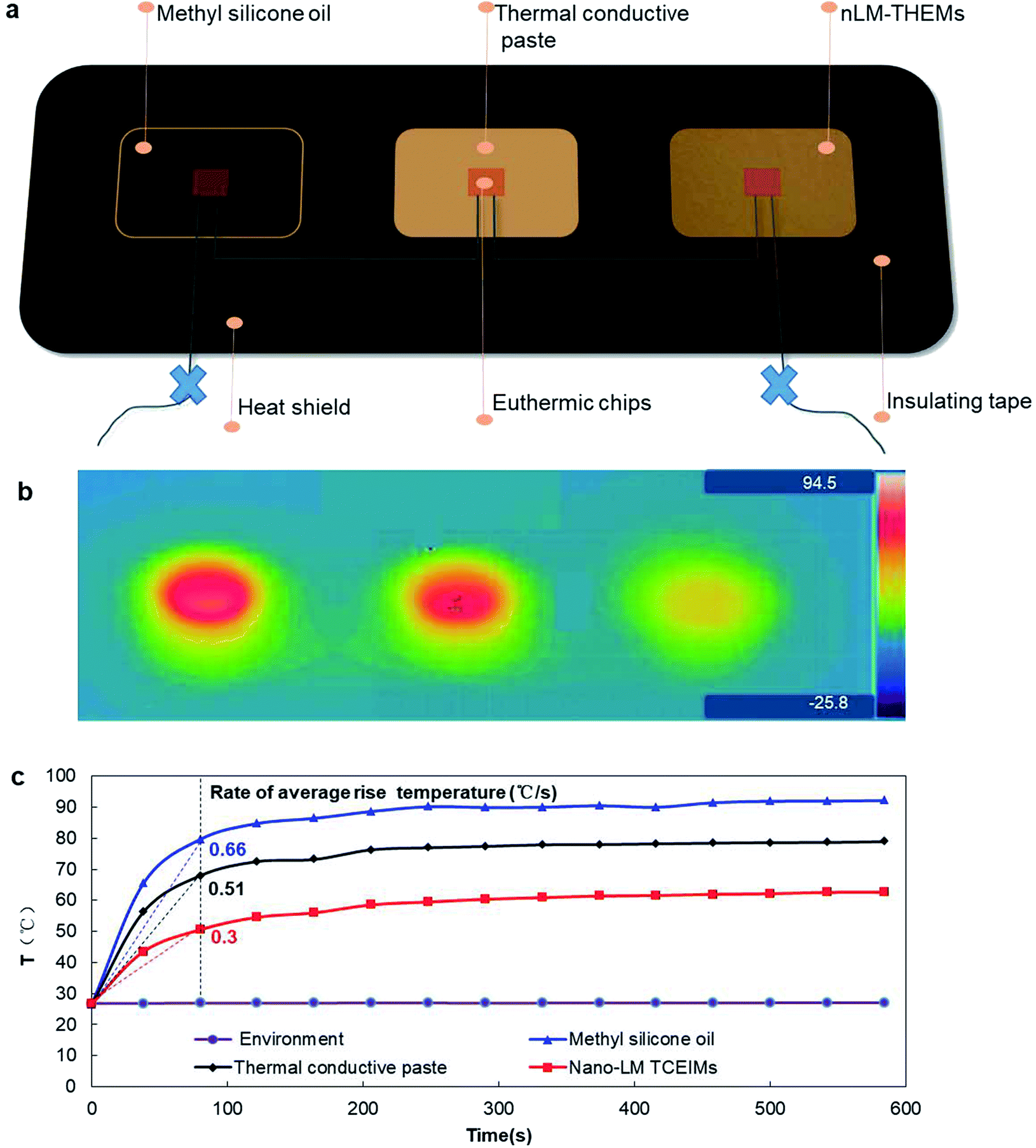 | ||
| Fig. 6 Actual cooling effect comparison of methyl silicone oil, thermal conductive paste and nLM-THEMs. (a) Experimental device diagram of the actual cooling effect of the three THEMs. (b) Temperature distribution thermal image of the test. (c) Core temperature of the euthermic chips as a function of time. | ||
The core temperature of the chips using silicone oil as the interface material stabilized at ∼90 °C and its average temperature rise rate is the highest at 0.66 (°C s−1) in the beginning, that with Deepcool Z9 thermal paste stabilized at ∼70 °C and its rate at 0.51 (°C s−1), and that with nLM-THEMs stabilized at ∼60 °C having the lowest average temperature rise rate at 0.3 (°C s−1) in the beginning (see Fig. 6(c)). This experimental result shows that the thermal diffusivity and thermal conductivity of then LM-THEMs are superior to that of commercial THEMs under the same heating conditions.
3.6 Young–Laplace equation reveals the higher stability of nLM-THEMs than micro-LM-THEMs
Here, we report a LM-based thermal interface composite with high thermal conductivity. The maximum thermal conductivity of the nLM-THEMs is up to 6.73 ± 0.04 W m−1 K−1(∼50 times more than the base polymer) and the volume resistivity is 2.09 × 10⁹ Ω m at 220 V. The ability of these high-thermal nLM-THEMs achieves superior thermal conductivity compared to conventional micro-LM-THEMs. The reason may be owing to the fact that the surfactants change the surface properties of the LM particles, in particular by reducing the surface tension of the LM.38 Unlike conventional LM-TIMs exhibiting a microstructure, the nLM-THEMs exhibit a dense array of smooth spherical particles that largely range from 100–800 nm in diameter at 22 °C. After sonication, Span 85 molecules are coated on the surface of the LM droplets, which prevents the LM droplets from merging immediately with each other when they come in contact. Span 85 is a hydrophobic surfactant with a HLB (hydrophile and lipophile balance) value of 1.8, which is well combined with methyl silicone oil. This can improve the LM dispersion effect in the THEMs, so a “sphere–sphere” combination can be seen in the structural state of the nLM-THEM microstructure. As shown in Fig. 1(a) and (b), each sphere is in direct contact with the surrounding spheres, but cannot be fused to form larger LM spheres because the surfaces area combination of surfactant and silicone oil.The “sphere–sphere” stable structure not only ensures an effective heat transfer path to improve the thermal conductivity of the material, but also achieves a uniform and stable nLM-THEMs. In the micro-LM-THEMs with no modification, the droplet structure is seen to be discontinuous with many “ditch back” features, with an appearance similar to the human brain. The structure of the “sphere–liquid–sphere” is extremely unstable. The liquid inclusion in the middle of the droplet will be “squeezed out” under external force, and these discontinuous droplets will re-contact and fuse into larger spheres. The LM in conventional micro-LM-THEMs continuously and gradually precipitates with time (Fig. 3(b)), whereupon the silicone oil is separated from the materials and accumulates on the surface (Fig. 3(b)). According to a previous study, a surface pressure of 1.7 MPa can cause a permanent change in a thin sheet (0.5 mm thick) of poly(dimethylsiloxane) embedded with inclusions of LM (gallium–indium–tin) microdroplets (2–30 μm in diameter), whereupon the film becomes electrically conductive with the concentrated stress.39 For EGaIn nanoparticles 100 nm in diameter it was found that the necessary sintering pressure is ∼10 MPa,40 while <1 MPa of pressure was required to sinter particles with diameters > 1 μm.41
According to Young–Laplace equation, when external force satisfies the following condition, there is possibility to trigger the liquid metal droplet deformation, if external force satisfies:
| F > P > 2γ/R |
Our results are consistent with the trend found in previous experiment and Young–Laplace equation, which may help to explain the increased stability of nLM-THEMs compared to that of micro-LM-THEMs as shown in Fig. 7. It is worth noting that the LM nanoparticles are further coated with polymer based surfactant, which means that LM nanoparticles may require more concentrated pressure to fuse. The inclusion of stable LM nanoparticles solves the problem of silicone oil exudation as well as preventing the corrosion risk brought by metal precipitation.
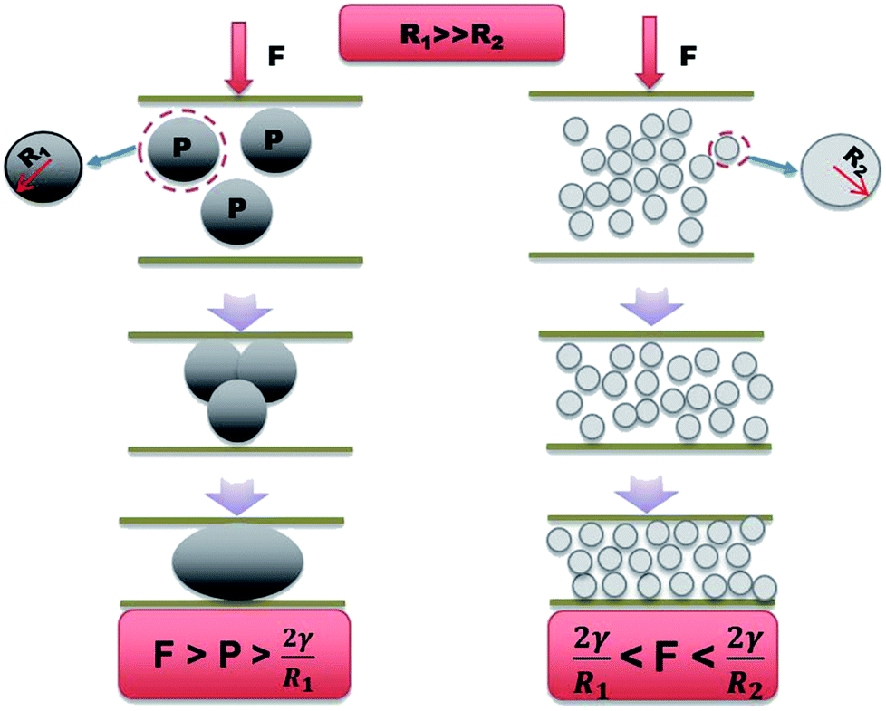 | ||
| Fig. 7 Schematic illustration showing the stability comparison between nLM-THEMs and micro-LM-THEMs. According to Young–Laplace equation, only when external force greater than 2γ/R2, it is possibility to trigger deformation of LM droplet. When 2γ/R2 < F < 2γ/R1, nLM-THEMs show high stability while micro-LM-THEMs have been merged with each other. | ||
The combination of high thermal conductivity and stability is especially critical for rapid heat dissipation in electrical packaging applications, such as chip cooling, in integrated circuits. The nLM-THEMs demonstrate excellent heat dissipation capabilities compared to commercial silicone oil and grease.
4 Conclusions
It is found that the nLM-THEMs can solve the stability problem exhibited by conventional micro-LM-THEMs, as well as prevent electricity leakage and corrosion. These results greatly recommend LM-based THEMs for further practical applications. It is shown that the use of ultrasonic dispersion and surfactant control can effectively achieve a uniform nanoscale LM in base materials. The maximum thermal conductivity of then LM-THEMs reaches 6.73 ± 0.04 W m−1 K−1 with filling ratios of 85.7% (v/v) while the volume resistivity is 2.09 × 10⁹ Ω m at 220 V, which ensures a high thermal conductivity and electric insulation. It is shown that the isotropic nLM-THEMs exhibit excellent cooling effects for the heating source. We anticipate that this nLM-THEM will be appropriate for a wide array of future applications in electronic packaging.Conflicts of interest
There are no conflicts to declare.Acknowledgements
This research was supported by the TIPC Director Fund (No. Y6AL021R2X), National Natural Science Foundation of China (No. 51706236), the Beijing Municipal Science & Technology Commission research fund (No. Z171100000417004) and CAS Key Laboratory of Cryogenics fund (No. cryo201711).References
- M. A. Chuan, M. Rong and M. Zhang, J. Mater. Eng., 2002, 40–45 Search PubMed.
- P. Bujard, G. Kuhnlein, S. Ino and T. Shiobara, IEEE Trans. Compon., Packag., Manuf. Technol., Part A, 1994, 17, 527–532 CrossRef CAS.
- P. Procter and J. Solc, IEEE Trans. Compon., Hybrids, Manuf. Technol., 1991, 14, 708–713 CrossRef CAS.
- C. L. Choy, W. H. Luk and F. C. Chen, Polymer, 1978, 19, 155–162 CrossRef CAS.
- F. Wang, J. M. Zhang and Q. G. Tang, Adv. Mater. Res., 2012, 427, 157–162 CrossRef.
- H. E. Chou, S. R. Yang, S. F. Wang and J. C. Sung, J. Electron. Packag., 2010, 132, 041015 CrossRef.
- Q. Wang, Z. Li, J. Wu and Y. Yin, International Conference on Condition Monitoring and Diagnosis, 2012, pp. 1110–1113 Search PubMed.
- T. Tomimura, S. Nomura and M. Okuyama, ASME/JSME 2007 Thermal Engineering Heat Transfer Summer Conference collocated with the ASME 2007 InterPACK Conference, 2007, vol. 3, p. 51 Search PubMed.
- W. Y. Zhou, S. H. Qi, H. Z. Zhao and N. L. Liu, Polym. Compos., 2007, 28, 23–28 CrossRef CAS.
- H. Yu, L. L. Li, T. Kido, G. N. Xi, G. C. Xu and F. Guo, J. Appl. Polym. Sci., 2012, 124, 669–677 CrossRef CAS.
- G. W. Lee, M. Park, J. Kim, J. I. Lee and H. G. Yoon, Composites, Part A, 2006, 37, 727–734 CrossRef.
- W. Y. Peng, X. Y. Huang, J. H. Yu, P. K. Jiang and W. H. Liu, Composites, Part A, 2010, 41, 1201–1209 CrossRef.
- C. C. Teng, C. C. M. Ma, K. C. Chiou and T. M. Lee, Composites, Part B, 2012, 43, 265–271 CrossRef CAS.
- Y. K. Shin, W. S. Lee, M. J. Yoo and E. S. Kim, Ceram. Int., 2013, 39, S569–S573 CrossRef CAS.
- Q. H. Mu, S. Y. Feng and G. Z. Diao, Polym. Compos., 2007, 28, 125–130 CrossRef CAS.
- M. H. Li, Y. Z. Wan, Z. F. Gao, G. Y. Xiong, X. M. Wang, C. B. Wan and H. L. Luo, Mater. Des., 2013, 51, 257–261 CrossRef CAS.
- A. A. Wereszczak, T. G. Morrissey, C. N. Volante, P. J. Farris, R. J. Groele, R. H. Wiles and H. Wang, IEEE T. Comp. Pack. Man., 2013, 3, 1994–2005 CAS.
- B. F. Xu, Z. D. Lin, C. M. Du, H. B. Lin, K. Y. Liang, W. P. Qiu and G. L. Yang, Mater. Res. Innovations, 2015, 19, S388–S391 Search PubMed.
- J. Xu, A. Munari, E. Dalton and A. Mathewson, J. Appl. Phys., 2009, 106, 114503–114823 CrossRef.
- S. Wang, Y. Cheng, R. Wang, J. Sun and L. Gao, ACS Appl. Mater. Interfaces, 2014, 6, 6481–6486 CAS.
- B. A. Cola, X. Xu and T. S. Fisher, ASME/JSME 2007 Thermal Engineering Heat Transfer Summer Conference collocated with the ASME 2007 InterPACK Conference, 2007, pp. 901–903 Search PubMed.
- A. S. Luyt, J. A. Molefi and H. Krump, Polym. Degrad. Stab., 2006, 91, 1629–1636 CrossRef CAS.
- Y. Agari and T. Uno, J. Appl. Polym. Sci., 2010, 32, 5705–5712 CrossRef.
- H. Kim and C. W. Macosko, Polymer, 2009, 50, 3797–3809 CrossRef CAS.
- Y. T. Sung, M. S. Han, K. H. Song, J. W. Jung, H. S. Lee, C. K. Kum, J. Joo and W. N. Kim, Polymer, 2006, 47, 4434–4439 CrossRef CAS.
- G. Droval, J. F. Feller, P. Salagnac and P. Glouannec, Polym. Adv. Technol., 2006, 17, 732–745 CrossRef CAS.
- L. Wang and G. Chen, J. Appl. Polym. Sci., 2010, 116, 2029–2034 CrossRef CAS.
- Y. Agari, A. Ueda, Y. Omura and S. Nagai, Polymer, 1997, 38, 801–807 CrossRef CAS.
- H. Yan, N. Sada and N. Toshima, J. Therm. Anal. Calorim., 2002, 69, 881–887 CrossRef CAS.
- H. M. Tu and L. Ye, Polym. Adv. Technol., 2009, 20, 21–27 CrossRef CAS.
- T. C. jing, Heat Conduction, Higher Education Press, 1992 Search PubMed.
- Y. Gao and J. Liu, Appl. Phys. A: Mater. Sci. Process., 2012, 107, 701–708 CrossRef CAS.
- S. Mei, Y. Gao, Z. Deng and J. Liu, J. Electron. Packag., 2014, 136, 011009 CrossRef.
- M. D. Bartlett, N. Kazem, M. J. Powellpalm, X. Huang, W. Sun, J. A. Malen and C. Majidi, Proc. Natl. Acad. Sci. U. S. A., 2017, 114, 2143 CrossRef CAS PubMed.
- T. S. Suzuki, Y. Sakka, K. Nakano and K. Hiraga, J. Am. Ceram. Soc., 2010, 84, 2132–2134 CrossRef.
- B. X. Wang, L. P. Zhou and X. F. Peng, Int. J. Heat Mass Transfer, 2003, 46, 2665–2672 CrossRef CAS.
- Y. G. Deng and J. Liu, Appl. Phys. A: Mater. Sci. Process., 2009, 95, 907–915 CrossRef CAS.
- J. N. Hohman, M. Kim, G. A. Wadsworth, H. R. Bednar, J. Jiang, M. A. Lethai and P. S. Weiss, Nano Lett., 2011, 11, 5104 CrossRef CAS PubMed.
- A. Fassler and C. Majidi, Adv. Mater., 2015, 27, 1928–1932 CrossRef CAS PubMed.
- J. W. Boley, E. L. White and R. K. Kramer, Adv. Mater., 2015, 27, 2355 CrossRef CAS PubMed.
- Y. Lin, C. Cooper, M. Wang, J. J. Adams, J. Genzer and M. D. Dickey, Small, 2015, 11, 6397–6403 CrossRef CAS PubMed.
- R. J. Larsen, M. D. Dickey, G. M. Whitesides and D. A. Weitz, J. Rheol., 2009, 53, 1305–1326 CrossRef CAS.
Footnote |
| † Electronic supplementary information (ESI) available. See DOI: 10.1039/c8ra00262b |
| This journal is © The Royal Society of Chemistry 2018 |