
 Open Access Article
 This Open Access Article is licensed under a Creative Commons Attribution-Non Commercial 3.0 Unported Licence
Trapping a moving droplet train by bubble guidance in microfluidic networks†
Longxiang Zhang,
Zhaomiao Liu *,
Yan Pang,
Xiang Wang,
Mengqi Li and
Yanlin Ren
*,
Yan Pang,
Xiang Wang,
Mengqi Li and
Yanlin Ren
College of Mechanical Engineering and Applied Electronics Technology, Beijing University of Technology, Beijing 100124, China. E-mail: lzm@bjut.edu.cn
First published on 27th February 2018
Abstract
Trapping a train of moving droplets into preset positions within a microfluidic device facilitates the long-term observation of biochemical reactions inside the droplets. In this paper, a new bubble-guided trapping method, which can remarkably improve the limited narrow two-phase flow rate range of uniform trapping, was proposed by taking advantage of the unique physical property that bubbles do not coalescence with two-phase fluids and the hydrodynamic characteristic of large flow resistance of bubbles. The flow behaviors of bubble-free and bubble-guided droplet trains were compared and analyzed under the same two-phase flow rates. The experimental results show that the droplets trapped by bubble-free guided trapping exhibit the four trapping modes of sequentially uniform trapping, non-uniform trapping induced by break-up and collision, and failed trapping due to squeezing through, and the droplets exhibit the desired uniform trapping in a relatively small two-phase flow rate range. Compared with bubble-free guided droplets, bubble-guided droplets also show four trapping modes. However, the two-phase flow rate range in which uniform trapping occurs is increased significantly and the uniformity of the trapped droplet array is improved. This investigation is beneficial to enhance the applicability of microfluidic chips for storing droplets in a passive way.
1 Introduction
Droplet-based microfluidics has gained considerable attention in academia and practical fields over the past decade, and shown much promise in nucleic acid analysis,1 disease diagnosis2 and drug screening3 due to its unique advantages over single-phase microfluidics, one of which is that there is no cross-contamination.4 For example, droplet-based microfluidics has been applied to the synthesis of noble-metal (Pd and Au) nanocrystals with uniform and well-controlled dimensions, morphologies, and compositions.5 The droplet train formed in microfluidic systems commonly moves at relatively high speeds (up to hundreds of millimeters per second), which results in shorter residence times and also a change in droplet position. Hence, it is essential to trap the moving droplet train into a fixed location for long-term monitoring of biochemical reactions. Recently, droplets encapsulating multicellular spheroids have been trapped into a microfluidic device to test anticancer treatments.6 The applications of trapping droplets also include the detection of single-molecules,7 assessment of drug efficacy,3 and development of subsequent manipulations (e.g., reagent addition).The methodology for trapping microdroplets can be either active8–10 or passive,11–17 but the passive method, which utilizes nothing more than the rational design of the microchannel, is more appreciated. The microfluidic trapping network (MTN) proposed in recent years is a typical passive configuration for trapping droplets, and has been successfully applied in the evaluation of protein crystallization, synthesis of inorganic materials and cell analysis. It shows apparent characteristics of low reagent consumption and short reaction time in some applications.3,18,19 The MTN consists of an array of repetitive trapping units in which each unit has a bypass and a trapping channel containing a hydrodynamic trap. The droplets are coupled with each other and exhibit complex nonlinear dynamics during the trapping process.20 This intricate hydrodynamic behavior is a complicated function of many parameters, including channel geometry, liquid properties, and flow conditions.21
Two passive approaches for storing droplets were described by Boukellal et al.,11 who also discussed the characteristics of droplet transportation. It is indicated that the droplet flow behavior depends on both the wettability of the channel walls and the droplet speed. Simon et al.14 experimentally and numerically depicted that the entrance width of the trap chamber, droplet size and interfacial tension between the two phases have significant effects on the droplet dynamics. The trapping-bypass channel resistance ratio (RT/RB) and the two-phase flow rate affect the path selection of the droplets and the flow behavior. Behavior transitions from the droplets being trapped at low flow rates to breaking up and squeezing at higher flow rates were experimentally demonstrated by Bithi et al.13 On the basis of the above investigations, a new method that utilizes coalescence between the moving and the static droplets, and the following droplet break-up, was subsequently proposed to obtain a highly monodisperse array of droplets at prescribed locations.21,22
Yet, the existing investigations mainly concentrate on the kinetics of biochemical reactions inside the trapped droplets,12,18,23–25 and an understanding of the fundamental mechanism of nonlinear dynamics in the MTN is still lacking. Additionally, the two-phase flow rate range in which sequentially uniform trapping occurs is narrow in the reported studies on trapping the droplet train, which severely limits the applicability of MTN-based microfluidics techniques. If a special medium that has physical properties characterized by non-coalescence with two-phase fluids and the hydrodynamic characteristic of large flow resistance guides the movement of the following droplets, the limited narrow flow rate range can be remarkably improved. It should be noted that an air bubble precisely possesses the physical properties of this sought-after medium. In view of this, a trapping mode diagram for bubble-free guided droplets is presented, and the causes of disordered behaviors are analyzed. Based on the defects of bubble-free guided trapping, a novel method is proposed to improve the performance of trapping devices, and the mechanisms behind the improvement are discussed.
2 Materials and methods
2.1 Microfluidic channel
There are two ways in which droplets can be trapped into the chamber of a trapping unit of the MTN: direct trapping and indirect trapping. The first droplet of the train goes directly into the trapping branch, which has lower hydrodynamic resistance (RT), while the subsequent droplet flows through the bypass since RT is significantly increased to RT > RB. Alternatively, the first several droplets select the bypass with lower hydrodynamic resistance (RB), while the subsequent droplet selects the other branch due to the increased resistance generated by the first several droplets. For direct trapping, as the droplet is subjected to larger continuous phase pressure, the critical flow rate at which the droplet staying in the chamber transitions to squeezing out is smaller compared with indirect trapping. This has also been confirmed by the existing experimental studies.13 Indirect trapping is preferred over direct trapping in wider applications. Hence, indirect trapping is studied in this work.A schematic of the microfluidic channel used to trap the droplet train is shown in Fig. 1(a) in the present study. All trapping units are based on the simple design principle that RT > RB, so one or several droplets in the front of the train enter the bypass, blocking the oil flow due to the resistance of the moving droplet, and then a subsequent droplet flows through the trapping arm and might get trapped in the circular chambers. In consideration of the difficulty in channel machining and the convenience of droplet visualization, RT/RB = 2.8 was designed in the present work. Both RB and RT were calculated by the analytical solution eqn (1)23 derived from the Poiseuille flow of a single phase in a rectangular channel along two branches, where μ is the viscosity of the liquid, and l, w, and h are the length, width, and depth of the channel, respectively. The error originating from bends, widening and narrowing is ignored.
 | (1) |
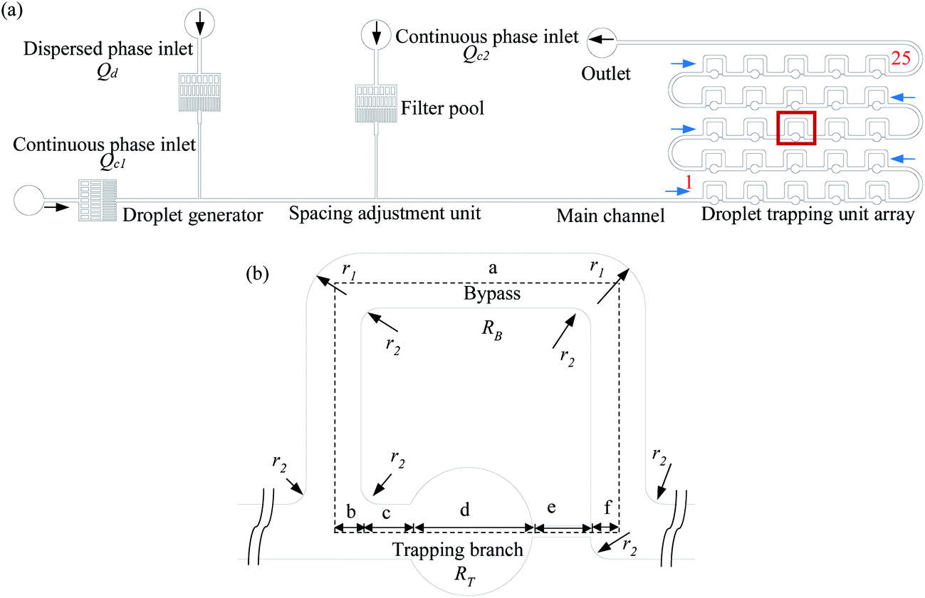 | ||
| Fig. 1 Schematic diagram of the experimental model, in which (a) is a schematic of the MTN, numbers 1 and 25 represent the trapping unit number, and the blue arrows indicate the droplet movement direction. (b) Represents an enlarged view of the trapping unit from the red rectangle in (a). | ||
The channel contains a droplet generator, a spacing adjustment unit, and 25 trapping units (numbered in accordance with S type). An enlarged view of a trapping unit is illustrated in Fig. 1(b). The trapping channel is split into five segments: b, c, d, e, and f; these facilitate the calculation of the hydrodynamic resistance and the description of the dimensions. Segment d corresponds to the circular chamber that is rectangular in cross-section. The approximation that a square, the length of one side of which is equal to the diameter of the circle, replaces the chamber in the calculation is applied. RT is the sum of the flow resistances of the five segments. The error induced by the approximation can be reasonably ignored since the flow resistance of the constriction is a main contributor to RT. The dimensions of the trapping unit are summarized in Table 1. The device is made of polydimethylsiloxane (PDMS) using standard photolithography techniques.26
| Length of each segment | Width of each segment | Depth | Arc radius | |||||||||||
|---|---|---|---|---|---|---|---|---|---|---|---|---|---|---|
| la | lb | lc | ld | le | lf | wa | wb | wc | wd | we | wf | h | r1 | r2 |
| 2104 | 75 | 120 | 350 | 160 | 75 | 150 | 150 | 150 | 350 | 34 | 150 | 120 | 150 | 50 |
2.2 Fluid materials
Sunflower oil was used as the oil phase due to its slight swelling effect on the channel walls. Deionized water was employed as the dispersed phase. The physical properties of the fluids are shown in Table 2, where μ and γ were measured using a rheometer (R/S Plus, Brookfield, USA) and an interfacial tension meter (A201, Solon Information Technology Co. Ltd., China), respectively.| Materials | Density ρ (kg m−3) | Viscosity μ (MPa s) | Interfacial tension γ1 (mN m−1) | |
|---|---|---|---|---|
| Continuous phase | Sunflower oil | 922 | 49.2 | 25.3 |
| Dispersed phase | Deionized water | 997.1 | 0.89 |
2.3 Experimental setup
The experimental setup is schematically illustrated in Fig. 2. Syringe pumps (Harvard Apparatus, Elite 1012, USA) were used to deliver the two-phase liquids into the channel. Three inlet ports were separately connected to 1000 μL glass syringes (Hamilton Company, USA) via peek capillary tubes, while the outlet port was connected to the drain. A high-speed camera (Keyence VW600C, Japan) was applied to visualize the transportation of the train at the frame rate of 30 Hz. The oil phase was pumped into the channel a few hours before the experiments to ensure that the walls were sufficiently wetted. | ||
| Fig. 2 Schematic diagram of the experimental setup. | ||
In the experiment, the normalized droplet length ζ = ld/wm ranged from 1.7 to 2.3, where ld and wm are the droplet length and the width of the main channel, respectively. The average droplet velocity (vd) varied from 0.19 mm s−1 to 2.16 mm s−1 in the main channel. The normalized droplet spacing λ = ls/la achieved by adjusting Qc2 was maintained at an approximately constant value of 0.40, such that hydrodynamic feedback between the droplets in the bypass and the incoming droplets in the main channel was induced, where ls is the droplet spacing in the main channel. The values of vd, ls, and ld were determined using a home-made Matlab program. The trapped droplet volume (Vd) was calculated by multiplying the height of the channel by the projected area of the droplet. The percentage of standard deviation of Vd divided by the average is equal to the polydispersity of the trapped droplet array after trapping. Each trapping experiment was done two times to calculate the average polydispersity.
2.4 Generation of the guiding bubble
The generation of a small guiding bubble is a key step. Learning from the approach of drop release mentioned by Boukellal et al.,27 all of the trapped drops were washed out by the high flow rate (such as Qc1 = 200 μL h−1, Qc2 = 300 μL h−1) in the oil phase. The connecting capillary tube was pulled out from the water phase inlet and then the two syringe pumps that deliver the oil were turned off. Oil stains on the PDMS chip surface were cleaned with a dustless cloth wetted by alcohol. Air spontaneously enters the channel from the recently opened inlet. The capillary tube that was pulled out is not re-inserted until air fills the punched inlet hole with a diameter of 0.75 mm and a length of about 2.5 mm. The filling process is monitored by a high-speed camera. The operation takes roughly 5 and a half minutes to form an air column with a length of about 8.8 w to 15 w in the main channel. As the whole column is passing through the T-junction of the drop generator, the two syringe pumps driving the oil are opened, starting a new capture. Representative results showing the formation of a guiding bubble from the gas column are shown in Fig. 3. It is noted that the bubble column could be cut into a relatively long column and several broken small bubbles at the T-junction of the spacing adjustment unit, and the small bubbles are trapped inside the chambers. When the long bubble enters the first trapping unit, it fragments into a longer portion moving in the bypass and a remnant that fills the whole trap chamber.25,28 Subsequently, the longer portion traverses several units (no more than 5) and is gradually dispersed into a guiding bubble with a length of 2.7 w to 2.9 w. Trapping does not occur in a uniform fashion until the guiding bubble is generated. The procedure for generating the leading bubble is reliable and reproducible. Although bubbles other than drops are stored in the first row of several chambers (1 to 4), the flow rate range in which T1 occurs is significantly broadened by this novel method. It should be noted that the trap chambers occupied by bubbles can be viewed as a waste tank, and enlarging the volume of the wasted chambers and reducing their number can improve the utilization of the MTN.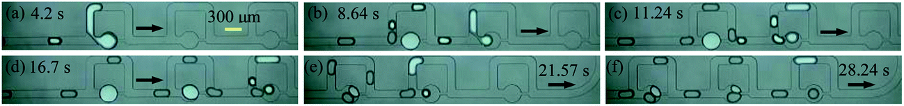 | ||
| Fig. 3 Experimental results showing generation of the guiding bubble. The arrow indicates the flow direction. (a)–(f) The generation of the bubble at different times. The time when the long bubble just enters the first junction of the MTN is defined as 0 s. The trapping unit no. of (a)–(d) are 1, 2, and 3. The trapping unit nos of (e) and (f) are 3, 4, and 5. | ||
3 Results and discussion
3.1 Classification of droplet trapping modes
Trapping modes existing in both cases are classified in this section to compare the trapping effects of the bubble-free and bubble-guided trapping methods. Four trapping modes were exhibited in the MTN: sequentially uniform trapping (T1), non-uniform trapping induced by break-up (T2), non-uniform trapping induced by collision (T3), and failed trapping due to squeezing through (T4), as shown in Fig. 4(a)–(d), respectively. Among them, T1 is desired in some applications due to there being no cross-contamination between droplets during the trapping and the acquisition of a highly uniform droplet array. For the bubble-free guided trapping method, the first two droplets in a train choose the bypass in a trapping unit, and then the third droplet is caught by the circular chamber. For the proposed method, the leading bubble flows through the side arm, and the next droplet gets trapped. This mode sequentially occurs in the MTN and is referred to as T1. | ||
| Fig. 4 Four trapping modes extracted from bubble-free guidance. The arrow indicates the movement direction of the droplets, and the red dotted circles show the critical trapping state. The scale bar of all images is 300 μm. The flow conditions of (a)–(d) are Qd = 12 μL h−1 Qc1 = 20 μL h−1 Qc2 = 20 μL h−1, Qd = 12 μL h−1 Qc1 = 20 μL h−1 Qc2 = 20 μL h−1, Qd = 24 μL h−1 Qc1 = 40 μL h−1 Qc2 = 32 μL h−1 and Qd = 40 μL h−1 Qc1 = 50 μL h−1 Qc2 = 60 μL h−1, respectively. The trapping unit nos of (a)–(d) are 1 and 2, 11 and 12, 19 and 20, and 11 and 12, respectively. | ||
Long droplets formed by the coalescence of two small droplets in the bypass uncontrollably fragment into two portions at the junction, leaving a broken daughter droplet in the trapping arm. This trapping is identified as T2. When the large droplet moves at high speed, another trapping mode characterized as T3 emerges: a portion of the droplet enters the bypass, while another portion enters the entrance of the trapping channel; before it wholly leaves the junction, the next droplet catches up, and the two neighboring droplets collide. As a result of this collision, the fragment in the trapping arm, or the fragment and its following droplet are trapped. If the differential pressure of the oil phase exerted on the trapped droplet is larger than the Laplace pressure difference between the front and rear caps, the static droplet is pushed out of the chamber. This mode is referred to as T4. It is further demonstrated that one or several modes are observed in a complete trapping process. If one mode occurs more frequently than the others do, this mode is referred to as the dominant mode. For these trapping modes, there are similarities and differences compared with those of Bithi et al.21 Specifically, the definition of T1 is the same as that of P1 (discrete drop parking). However, T2 is distinguished from P3 (drop parking due to collision-induced break-up) since the long droplet with no surfactant coating in T2 is formed by the coalescence of two small droplets in the bypass, while the long droplet with a surfactant coating in P3 is formed by generation in the upstream T junction.
3.2 Comparison of trapping effects by bubble-free and bubble guidance
A diagram of the trapping modes by bubble-free guidance is illustrated in Fig. 5(a). Small droplets at low speeds were trapped by T1 only in a very narrow range, where the polydispersity was smaller than 14%. The polydispersity depends only on the uniformity of the droplets formed upstream. For droplets of medium speeds and sizes, T1, T2 and T3, with T1 occurring more frequently than the others, were observed in a wide range and the polydispersity ranged from 15% to 21%. For large droplets moving at high speeds, T1, T2 and T3 with T2 dominating were indicated in a small range and the polydispersity was larger than 21%. However, T4 was exhibited when the flow rate exceeded a critical value. | ||
| Fig. 5 Trapping mode diagram for bubble-free and bubble guidance (bold indicates the dominant mode); (a) is bubble-free guided trapping and (b) is bubble-guided trapping. | ||
A diagram of the trapping modes of the droplet train by bubble guidance is shown in Fig. 5(b). Compared with bubble-free guided trapping, the region of T1 (green symbol) is broadened significantly. Specifically, the data points of T1 are increased from 2 (Fig. 5(a)) to 14. The polydispersity, determined only by the dimensions of the upstream droplets, is less than 14% at the tested flow rates. Therefore, the flow rate range in which a uniform droplet array is produced is also greatly enhanced by bubble guidance. Taking Qd = 12 μL h−1 Qc1 = Qc2 = 20 μL h−1 as an example to comparatively show the advancement in detail: T1, T2 and T3 occurred 15, 6 and 4 times, respectively, using the bubble-free guided trapping method, and the polydispersity was 19%; all droplets were trapped in the T1 mode (see movie S2, ESI†) and the polydispersity was 8% using bubble-guidance.
The fact that there is no cross-contamination between the reaction vessels is one of the most prominent advantages of drop-based microfluidics; however, both T2 and T3 occur in a large range in Fig. 5(a), which not only causes mass transfer between the droplets, but also substantially degrades the uniformity of the trapped droplets. These shortcomings greatly limit the possible biochemical reactions (such as the observation of worm behavior29), particularly those which have strict requirements for avoiding cross-contamination between reagents, and are sensitive to reagent consumption. It is therefore essential to analyze the principal mechanism of the undesired trapping events in bubble-free guided trapping.
3.3 Mechanism of undesired non-uniform trapping by bubble-free guidance
Taking Qd = 12 μL h−1 Qc1 = Qc2 = 20 μL h−1 as a representative example to demonstrate the mechanism of undesired non-uniform trapping by bubble-free guidance in detail, T1, T2, and T3 were observed 15, 6, and 4 times, respectively, in a complete trapping process (see movie 1, ESI†). When droplets A and B pass through two trapping units (no. 1 and 2), the path selection of the droplets is shown in Fig. 6. The normalized speed of A and B (α = vA/vC and β = vB/vC), and the normalized centroid distance between A and B (ϕ = ls/w) over time are shown in Fig. 7(a) and (b), respectively, and vC is the velocity of the continuous phase in the main channel. The time at which the first droplet enters the first junction of the MTN is marked as 0 s. | ||
| Fig. 6 Paths of droplets by bubble-free guided trapping. The scale bar of all images is 300 μm (A, B, C and D represent the first four droplets of the train). | ||
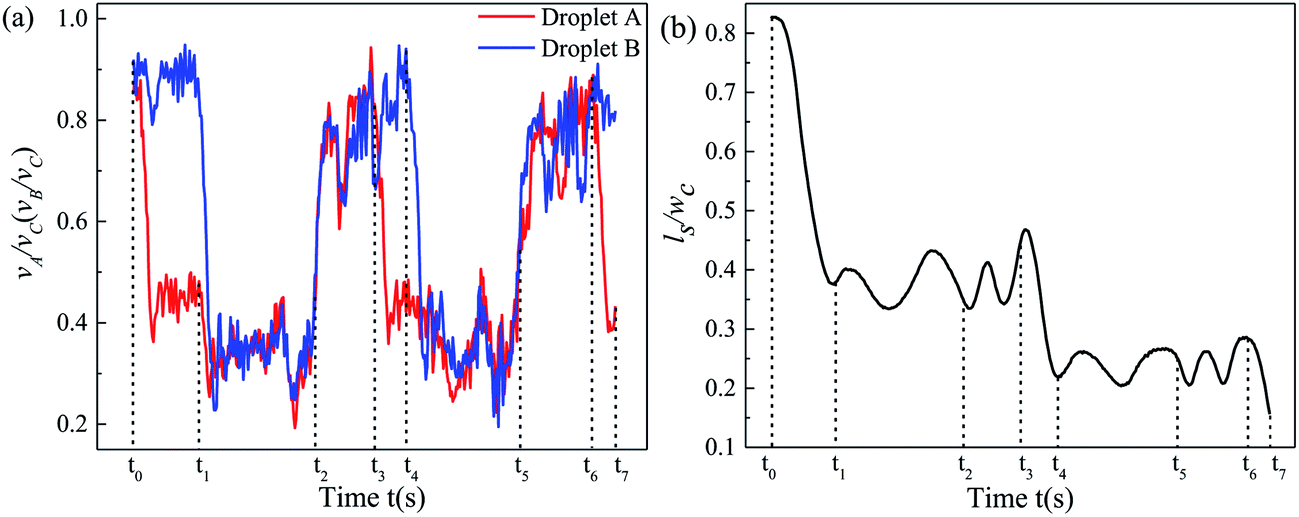 | ||
| Fig. 7 Variation of the speeds of two neighboring droplets and their spacing. (a) Graph showing how the dimensionless speeds of A and B (vA/vC and vB/vC) vary with time. (b) Graph showing how the dimensionless centroid distance between A and B (Is/wc) varies with time. | ||
The initial spacing of the droplets is heavily disturbed. Specifically, for t0 ∼ t1 (from the time point when the front tip of A just arrives at the junction to the time when the front tip of B arrives), α decreases due to partial oil leakage through the trapping arm. Meanwhile, β maintains the original value of the train, and thus B effectively approaches A, and ϕ decreases. For t1 ∼ t2 (from the time point when the front tip of B arrives at the junction to C being trapped), α is reduced again since B hampers the addition of oil to the bypass. Additionally, α is slightly increased due to some of the oil in the trapping arm being blocked by C and more oil being delivered into the bypass. In contrast, for t2 ∼ t3 (from the time point when C is trapped to the front tip of A arriving at the junction of the next unit), α and β approximately recover to the initial value of the train (neglecting the gutter flow in the trapping arm), which is attributed to oil only flowing through the bypass. For t3 ∼ t6, the evolution of α, β, and ϕ over time is analogous to that of t0 ∼ t3.
However, for t6 ∼ t7, ϕ decreases once more such that A and B collide. Subsequently, there are three trapping events: (i) B is trapped and A moves through the bypass; (ii) A and B fuse into a long droplet, which fragments into two portions at the junction and one daughter droplet gets trapped, i.e. T2 (see Fig. 4(b)); (iii) the deformation at the junction induced by complex hydrodynamic forces is evidently presented when a larger droplet travels at high speed, resulting in a portion entering the bypass and a portion entering the trapping branch. If the whole body of A does not leave the junction until B catches up, A and B collide and break, behaving as indicated by T3 (see Fig. 4(c)). Thus, the inherent instability of the droplet velocity and the spacing between neighboring droplets is the principal mechanism of the unfavorable events in the MTN.
To address the concerns regarding the shortcoming of the narrow flow rate range of T1 and the non-uniform trapped droplet array, a longer water plug is introduced to fill the microfluidic parking network. Then, oil is injected to shear off the dispersed phase at the junctions in an orderly manner.30 An alternative method was proposed, which utilizes the coalescence between the moving and parked droplets and subsequent break-up to automatically correct the volume of trapped surfactant-free droplets.21 Both approaches readily generate a monodisperse droplet array. The former is incompatible with parking droplets in which insoluble materials are encapsulated due to the medium inside the trapped droplets distributing in a random manner.30 The latter is not suitable for systems where an excess of surfactant is added (a standard operation in droplet-based microfluidics), because droplet coalescence and volume rectification do not occur in the MTN. Moreover, undesired interfacial mass transfer induced by coalescence heavily hampers applications where each droplet serves as an individual reaction vessel. A bubble-guided trapping method distinct from that of Bithi et al.21 is proposed in the present study, which is suitable for both systems in which a surfactant is not added, and systems in which one is added.
3.4 Mechanism of improved trapping by bubble guidance
To maintain the original content of each droplet in a train and upgrade the uniformity of the trapped droplets, we can reduce or eliminate the events of coalescence and collision. Thus, a novel approach where an additional bubble guides the droplet train to move through the MTN is proposed. This takes advantage of the hydrodynamic and physical properties of the bubble characterized by a large hydrodynamic resistance, as well as non-coalescence with two-phase liquids.Likewise, Qd = 12 μL h−1 Qc1 = Qc2 = 20 μL h−1 is taken as an example to show the mechanism of improved trapping by bubble guidance. The time when the bubble just enters the first junction of the MTN is defined as 0 s. Snapshots of droplets travelling through three units (no. 11 to 13) at six moments are indicated in Fig. 8 to clearly illustrate the trapping mechanism. The droplets (1, 2, and 3) next to the bubble directly go through the trapping arm and then get parked, effectively avoiding coalescence and collision. The frequency at which T1 occurs and the polydispersity are significantly improved. In contrast, the first two droplets of a train always move through the bypass during bubble-free guided trapping and the undesired events as shown in Fig. 6 are readily presented. Thus, bubble guidance makes the droplets more ordered in the MTN compared with those produced by bubble-free guidance, and this is beneficial to expand the flexibility of the MTN and its usability in lab on a chip applications, where mass transfer between reactors is not expected.
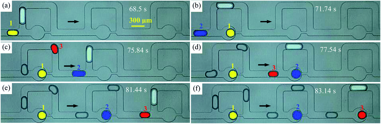 | ||
| Fig. 8 Droplet trapping by bubble guidance (Qd = 12 μL h−1, Qc1 = 20 μL h−1, Qc2 = 20 μL h−1, the arrow indicates the flow direction). (a)–(f) Snapshots of droplets at six critical moments. | ||
According to the qualitative analysis of the path selection of the droplets in Fig. 8, the improvement caused by the bubble is predominantly attributed to the hydrodynamic characteristic of its large resistance at the tested flow rates. All T1 events in Fig. 5(b) follow the rule that the bubble moves along the bypass and the subsequent droplet is trapped, indicating that Qct > Qcb, as schematically shown in Fig. 9(a). However, bubble-free guided trapping is different as the first two droplets choose the bypass and the third is trapped, indicating that Qcb > Qct, as schematically shown in Fig. 9(b). The trapping effects induced by bubble guidance are equivalent to those induced by two-droplet guidance (assuming that bubble-free guided trapping is guided by droplets). It is roughly inferred that ΔPB ≈ 2ΔPD, where ΔPB and ΔPD are the pressure drop of the bubble and droplet, respectively. If a droplet whose length is equal to that of a bubble acts as the guider, as shown in Fig. 9 (c1), the two neighboring droplets flow through several units and fuse as illustrated in Fig. 9 (c2). They do not fuse in bubble-guided trapping as shown in Fig. 9 (c3) and (c4) even if the bubble and droplet come into contact. Thus, the advancement is also attributed to the unique physical property that the bubble is immiscible with two-phase fluids.
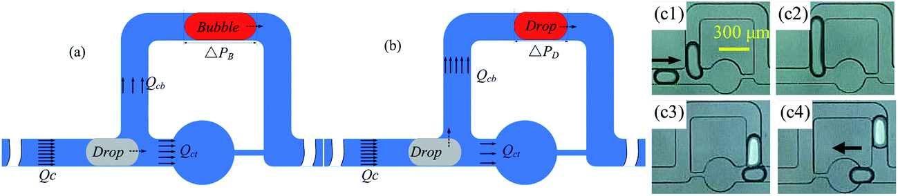 | ||
| Fig. 9 Schematic diagram of the oil flow distribution in a trapping unit; the dotted arrow indicates the movement direction of the droplet. (a) Oil distribution in a trapping unit by bubble guidance. (b) Oil distribution in a trapping unit by bubble-free guidance. (c) Comparison of bubble-free and bubble-guided trapping; the arrow indicates the flow direction. | ||
The resistive feature difference between the two guiding media causes two trapping effects. Therefore, it is necessary to explore the factors that lead to this difference. Wong et al.31 gave eqn (2) with the aid of numerical computation to quantify the pressure drop of a bubble in a rectangular channel:
| ΔP = ηCa2/3 | (2) |
 agrees well with that deduced from the law of droplet path selection (Fig. 9(a) and (b)). Thus, the desired trapping induced by bubble guidance is mainly attributed to the large hydrodynamic resistance compared with bubble-free guided trapping.
The hydrodynamic resistance of a bubble or droplet in a straight or curved microchannel is a complex and fundamental research aspect and related to numerous factors, including flow velocity, spacing, and viscosity.20,34–36 Existing studies are focused on the qualitative analysis and indirect measurement of straight microchannels; it is challenging to quantitatively measure and compare their hydrodynamic resistance under the same conditions and further research is needed.
4 Conclusions
The trapping modes of a moving droplet train by bubble-free and bubble guidance are comparatively studied in this paper. For bubble-free guided trapping, disordered non-uniform trapping induced by break-up and collision is observed in a wide range and heavily attributed to the intrinsic instability of droplet spacing in the microfluidic trapping network. In contrast, the flow region of sequentially uniform trapping is significantly broadened by bubble-guided trapping and this is predominantly attributed to the large hydrodynamic resistance of the bubble.The bubble-guided trapping method also makes significant progress in addressing the concerns regarding reagent non-uniformity in the network, and is especially suitable for applications (e.g. the observation of Caenorhabditis elegans) where mass transfer between micro-reactors should be avoided. Although the size of the bubble is not accurate due to empirical control, the highlighted results provide an ideal scenario and guidelines to improve the performance and suitability of microfluidic chips for passive micro-reactor storage.
Conflicts of interest
There are no conflicts to declare.Acknowledgements
The authors gratefully acknowledge the support of the National Natural Science Foundation of China (Grant No. 11572013, and No. 11702007).References
- Y. Ding, J. Choo and A. J. deMello, Microfluid. Nanofluid., 2017, 21, 58 CrossRef.
- Y. Piao, D. J. Han, M. R. Azad, M. Park and T. S. Seo, Biosens. Bioelectron., 2015, 65, 220–225 CrossRef CAS PubMed.
- M. Courtney, X. Chen, S. Chan, T. Mohamed, P. P. N. Rao and C. L. Ren, Anal. Chem., 2017, 89, 910–915 CrossRef CAS PubMed.
- S. Ralf, B. Martin, P. Thomas and H. Stephan, Rep. Prog. Phys., 2012, 75, 016601 CrossRef PubMed.
- L. Zhang, G. Niu, N. Lu, J. Wang, L. Tong, L. Wang, M. J. Kim and Y. Xia, Nano Lett., 2014, 14, 6626–6631 CrossRef CAS PubMed.
- K. S. McMillan, M. Boyd and M. Zagnoni, Lab Chip, 2016, 16, 3548–3557 RSC.
- M. Srisa-Art, A. J. deMello and J. B. Edel, J. Phys. Chem. B, 2010, 114, 15766–15772 CrossRef CAS PubMed.
- H.-H. Jeong, B. Lee, S. H. Jin, S.-G. Jeong and C.-S. Lee, Lab Chip, 2016, 16, 1698–1707 RSC.
- S. H. Jin, H.-H. Jeong, B. Lee, S. S. Lee and C.-S. Lee, Lab Chip, 2015, 15, 3677–3686 RSC.
- R. W. Rambach, K. Linder, M. Heymann and T. Franke, Lab Chip, 2017, 17, 3422–3430 RSC.
- H. Boukellal, S. Selimovic, Y. Jia, G. Cristobal and S. Fraden, Lab Chip, 2009, 9, 331–338 RSC.
- W. Shi, J. Qin, N. Ye and B. Lin, Lab Chip, 2008, 8, 1432 RSC.
- S. S. Bithi and S. A. Vanapalli, Biomicrofluidics, 2010, 4, 044110 Search PubMed.
- M. G. Simon, R. Lin, J. S. Fisher and A. P. Lee, Biomicrofluidics, 2012, 6, 014110 CrossRef PubMed.
- G. Amselem, P. T. Brun, F. Gallaire and C. N. Baroud, Phys. Rev. Appl., 2015, 3, 054006 CrossRef.
- W. Shi, H. Wen, Y. Lu, Y. Shi, B. Lin and J. Qin, Lab Chip, 2010, 10, 2855–2863 RSC.
- W. H. Tan and S. Takeuchi, Proc. Natl. Acad. Sci. U. S. A., 2007, 104, 1146–1151 CrossRef CAS PubMed.
- S. S. Bithi and S. A. Vanapalli, Sci. Rep., 2017, 7, 41707 CrossRef CAS PubMed.
- X. Chen and C. Ren, RSC Adv., 2017, 7, 16738–16750 RSC.
- V. Labrot, M. Schindler, P. Guillot, A. Colin and M. Joanicot, Biomicrofluidics, 2009, 3, 012804 CrossRef PubMed.
- S. S. Bithi and S. A. Vanapalli, Soft Matter, 2015, 11, 5122–5132 RSC.
- S. S. Bithi, W. S. Wang, M. Sun, J. Blawzdziewicz and S. A. Vanapalli, Biomicrofluidics, 2014, 8, 034118 Search PubMed.
- W.-C. Cheng, Y. He, A.-Y. Chang and L. Que, Biomicrofluidics, 2013, 7, 064102 CrossRef PubMed.
- H.-H. Jeong, S. H. Jin, B. J. Lee, T. Kim and C.-S. Lee, Lab Chip, 2015, 15, 889–899 RSC.
- A. Dewan, J. Kim, R. H. McLean, S. A. Vanapalli and M. N. Karim, Biotechnol. Bioeng., 2012, 109, 2987–2996 CrossRef CAS PubMed.
- W.-A. C. Bauer, M. Fischlechner, C. Abell and W. T. S. Huck, Lab Chip, 2010, 10, 1814–1819 RSC.
- H. Boukellal, S. Selimovic, Y. Jia, G. Cristobal and S. Fraden, Lab Chip, 2009, 9, 331–338 RSC.
- M. Sun, S. S. Bithi and S. A. Vanapalli, Lab Chip, 2011, 11, 3949–3952 RSC.
- W. Shi, J. Qin, N. Ye and B. Lin, Lab Chip, 2008, 8, 1432–1435 RSC.
- M. Sun, S. S. Bithi and S. A. Vanapalli, Lab Chip, 2011, 11, 3949–3952 RSC.
- H. Wong, C. J. Radke and S. Morris, J. Fluid Mech., 1995, 292, 95–110 CrossRef.
- P. Parthiban and S. A. Khan, Lab Chip, 2012, 12, 582–588 RSC.
- C. N. Baroud, F. Gallaire and R. Dangla, Lab Chip, 2010, 10, 2032–2045 RSC.
- S. A. Vanapalli, A. G. Banpurkar, D. van den Ende, M. H. G. Duits and F. Mugele, Lab Chip, 2009, 9, 982–990 RSC.
- M. J. Fuerstman, A. Lai, M. E. Thurlow, S. S. Shevkoplyas, H. A. Stone and G. M. Whitesides, Lab Chip, 2007, 7, 1479–1489 RSC.
- P. Sajeesh, M. Doble and A. K. Sen, Biomicrofluidics, 2014, 8, 054112 CrossRef CAS PubMed.
Footnote |
| † Electronic supplementary information (ESI) available. See DOI: 10.1039/c7ra13507f |
| This journal is © The Royal Society of Chemistry 2018 |