
 Open Access Article
 This Open Access Article is licensed under a Creative Commons Attribution-Non Commercial 3.0 Unported Licence
Coaxial heterojunction carbon nanofibers with charge transport and electrocatalytic reduction phases for high performance dye-sensitized solar cells†
Yuan-Hua Wanga,
Hai-Qiu Fanga,
Qiang Donga,
Duan-Hui Sib,
Xue-Dan Songb,
Chang Yua and
Jie-Shan Qiu *ac
*ac
aCarbon Research Laboratory, Liaoning Key Lab for Energy Materials and Chemical Engineering, State Key Lab of Fine Chemicals, School of Chemical Engineering, Dalian University of Technology, Dalian 116024, China. E-mail: jqiu@dlut.edu.cn
bState Key Laboratory of Fine Chemical, School of Chemistry, Dalian University of Technology, Dalian 116024, China
cSchool of Chemical Engineering and Technology, Xi'an Jiaotong University, Xi'an, 710049, China
First published on 13th February 2018
Abstract
Novel coaxial heterojunction carbon nanofibers, fabricated by electro-spinning a mixture of hydro-pitch and polyacrylonitrile, served as the counter electrode for dye-sensitized solar cells. Their high power conversion efficiency, being comparable to that of Pt CE, was achieved due to their good conductivity and high heteroatom content.
The counter electrode (CE) in dye-sensitized solar cells (DSSCs) has multiple functions, including the catalytic reduction of I3− to I− and the regeneration of dye molecules, and is one of the key dominant components that governs the practical applications of DSSCs to a great degree.1 Noble metal platinum (Pt) with its low electrical resistance and excellent electrocatalytic activity was the first to be applied as such and is now widely used as CEs in DSSCs. However, there is limited availability of Pt sources, and this has led to the high cost of CEs, which has hindered the practical applications of DSSCs.2 To date, various efforts have been made to develop techniques for the production of inexpensive yet high performance CEs to replace the Pt CEs. Of the alternatives now available, carbon materials that are categorized as zero-dimensional (0D) to three-dimensional (3D) structures have attracted much attention as candidates for Pt-free electrodes in view of the advantages of low cost as well as good electrochemical stability; these include carbon black,3 carbon nanoparticles,4 carbon nanotubes,5–9 graphene,10–14 and graphite15 and their composites.16–19 It is believed that a large quantity of defects in the carbon CEs may lead to high catalytic activities, while good electric conductivity can result in fast charge transportation. Nevertheless, how to combine and integrate the high electrical conductivity and abundant defects into one carbon electrode in a balanced way to fabricate high performance CEs with tuned structure remains a major challenge.
Recently, one dimensional (1D) core–shell nanofibers have received much attention because a good combination of electrical conductivity and catalytic activity can be realized and achieved in one electrode material.20 However, the core and shell in these fibers are two separate phases, which limits the rapid charge transition and increases the electrical resistance when such nanofibers are used as CEs in DSSCs. Moreover, the tedious and complicated fabrication process greatly limits their large-scale production. As such, it is necessary to explore a new approach for this kind of material, in which electrical conductivity and catalytic activity are combined well.
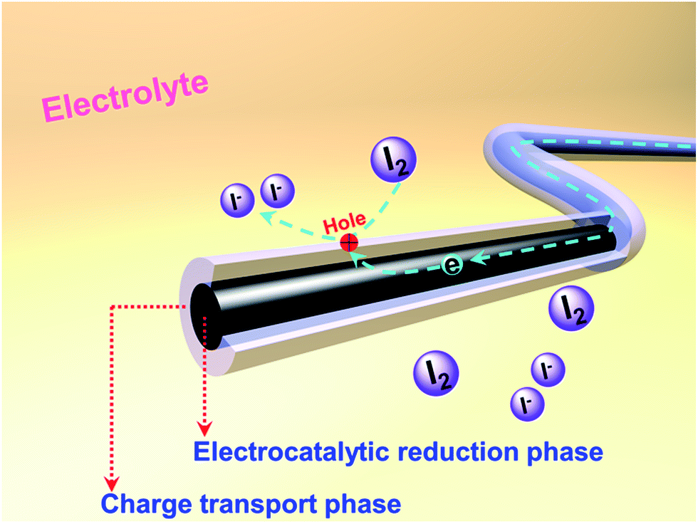
Herein, we present 1D coaxial carbon nanofibers (CNFs) fabricated by the electrospinning method from two kinds of carbon precursors: hydrogenated pitch and polyacrylonitrile (PAN). The adopted hydro-pitch (HP) features planar aromatic hydrocarbon molecules and is more easily transformed into an optically anisotropic, graphitizable carbon structure,21 thus leading to high conductivity (Table S1, ESI†). PAN tends to form a carbonaceous structure with high nitrogen (N) content and abundant defects; it is widely acknowledged that high electrochemical activities could be achieved by the different nitrogen species and defects.7,16,17,22–24 Benefiting from different nucleation mechanisms, a novel coaxial core/shell structure has been produced within the matrix, in which hydro-pitch contributes to the core phase, while PAN is responsible for the shell phase. Such CNFs with two phases and heterogeneous characteristics are very unique when they are applied as CEs in DSSCs, with the core playing the role of cable tunnel for charge transporting and the shell providing active sites for catalyzing the reduction of I3− to I−, as shown in Scheme 1.
 | ||
| Scheme 1 Illustration of the structure and functions of heterojunction carbon nanofibers as CEs in DSSCs. | ||
The process of fabricating our CNFs (denoted as 0.15-HCNF and 1-HCNF, in which 0.15 and 1 are the weight ratios between hydro-pitch and PAN) is illustrated in Fig. S5,† and the morphologies of different CNFs and their corresponding diameter distributions are shown in Fig. 1a–c and a1–c1. The average diameter is 0.33 μm for PAN CNFs (PCNF), 0.36 μm for 0.15-HCNF, and 0.76 μm for 1-HCNF, indicative of a size-increased behavior with the increase in the ratio between the hydro-pitch and PAN. The obtained CNFs in sample 1-HCNF are cross-linked or joined together, as can be seen in Fig. 1c, leading to the inner parts being exposed and the observation of different phases.
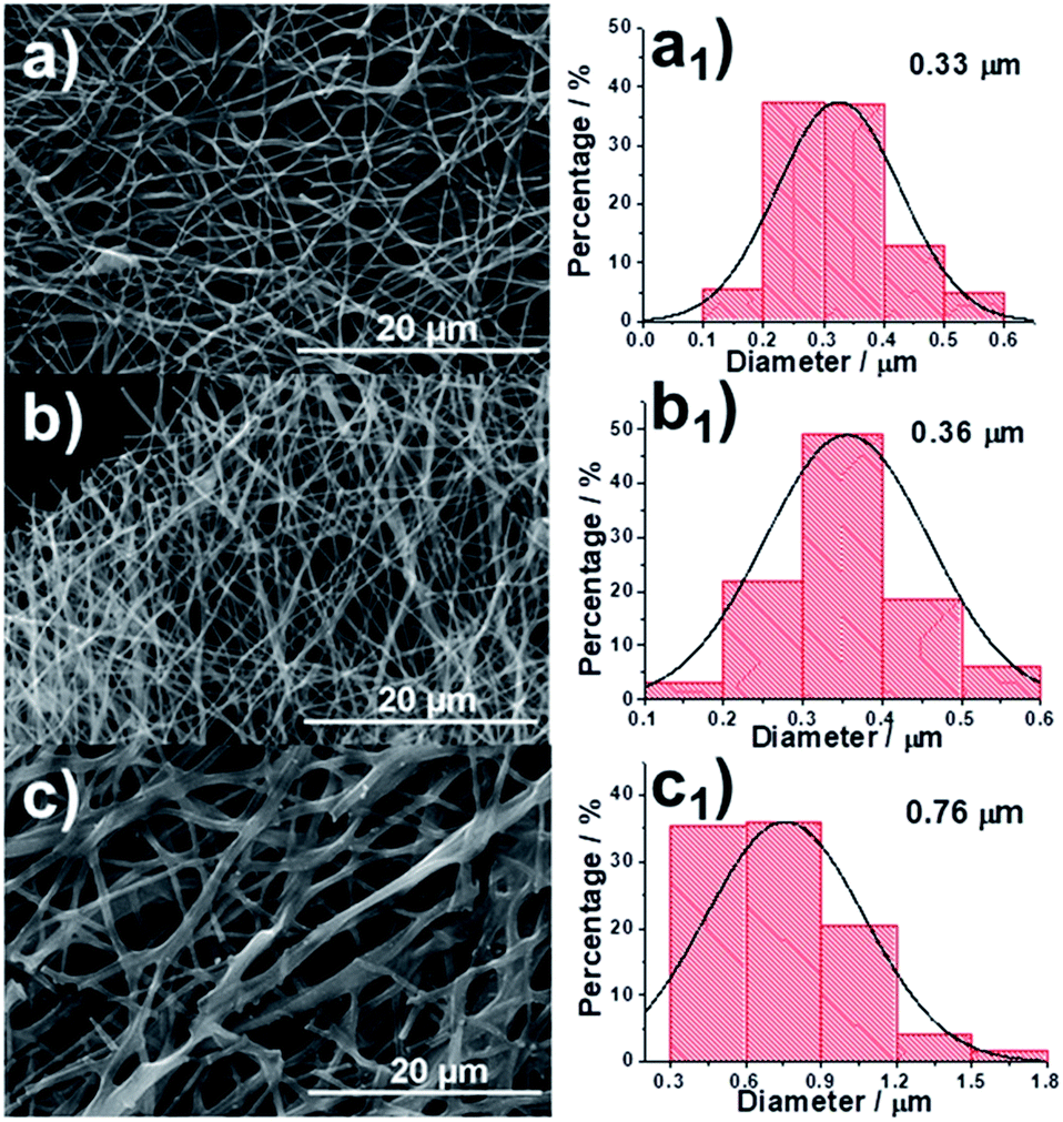 | ||
| Fig. 1 Scanning electron microscopy (SEM) images of (a) PCNF, (b) 0.15-HCNF and (c) 1-HCNF. | ||
The HCNFs were examined in much detail by transmission electron microscopy (TEM) to yield information about the inner structure, and the typical TEM images are shown in Fig. 2. It can be clearly seen that two phases in the axial direction are obviously observed in the HCNF samples (Fig. 2b and c) in comparison to PCNF (Fig. 2a). Energy-dispersive X-ray spectra (EDX) of the shell region show the high nitrogen content of 9.3 at% (Fig. 2e), which implies that the carbon shell is derived from PAN. To further gain insight into the contributions of these two precursors, sample 1-HCNF was treated with KOH at high temperature to remove the shell, and the corresponding sample was further characterized by TEM and EDX, the detailed results of which are shown in Fig. 2d and f. It can be seen that the shell layer was removed, and the content of nitrogen was only 1 at% in the core phase (Table S2, ESI†), in comparison to there being only 0.4 wt% (Table S3, ESI†) of nitrogen in the hydro-pitch.
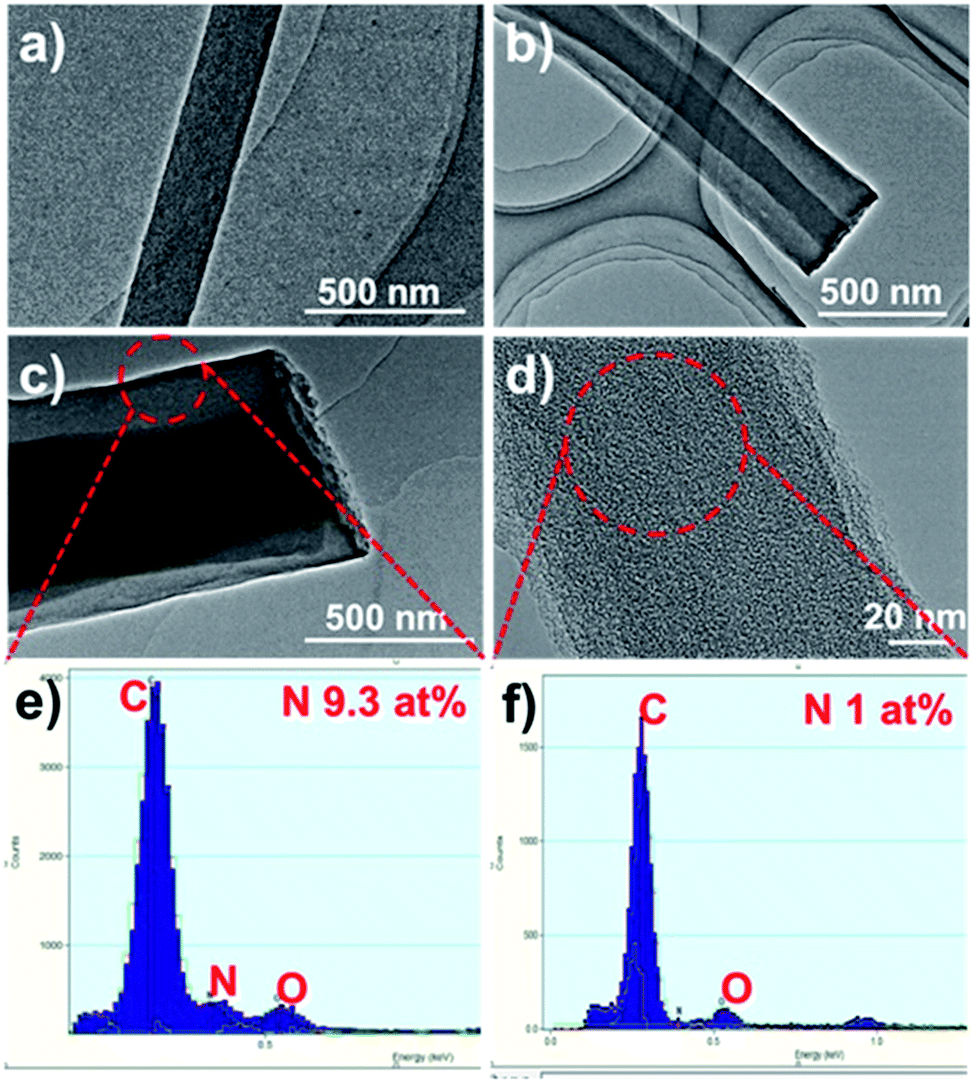 | ||
| Fig. 2 TEM images of (a) PCNF, (b) 0.15-HCNF, (c) 1-HCNF, and (d) the core of the 1-HCNF fiber after KOH treatment for 1 h at 700 °C in N2. (e and f) The EDX spectra of the fiber shell and core. | ||
With all of this information in mind, it was deduced that the core phase was mainly derived from the hydro-pitch, while the shell was mainly from PAN.
It is interesting that this result is different from that reported by Yang.25 In general, the low molecular weight pitch tends to be pushed to the outer surface during the solvent evaporation process.26,27 Nevertheless, in the present system the hydro-pitch is more easily fixed in the inner part, which was evidenced by density functional theory (DFT) calculations (Fig. 3). As shown in Fig. 3a, the binding energy between the hydro-pitch and two PAN units (EHP) is 5.6 kcal mol−1, which is 1.3 kcal mol−1 higher than that between pitch and PAN units (EP, 4.3 kcal mol−1). When three PAN units were applied, an increase of 25% was observed for EHP, which reached 7.0 kcal mol−1. The newly formed hydrogen bonding between aliphatic hydrogen in hydro-pitch and the cyano group in the PAN unit is responsible for the remarkable increase in binding energy, while the number of EP only slightly increased from 4.3 to 4.4 kcal mol−1, and no new bonding was observed. As a result, compared to the pitch, the hydro-pitch could be more easily fixed in PAN units due to the strong binding caused by the multi-interaction between the aliphatic hydrogen and cyano groups. In addition, the hydro-pitch is always wrapped by several PAN long chain molecules, as shown in Fig. S5.† Therefore, a kind of heterojunction core–shell structure was finally produced, in which the core was attributed to the hydro-pitch while the shell was attributed to PAN.
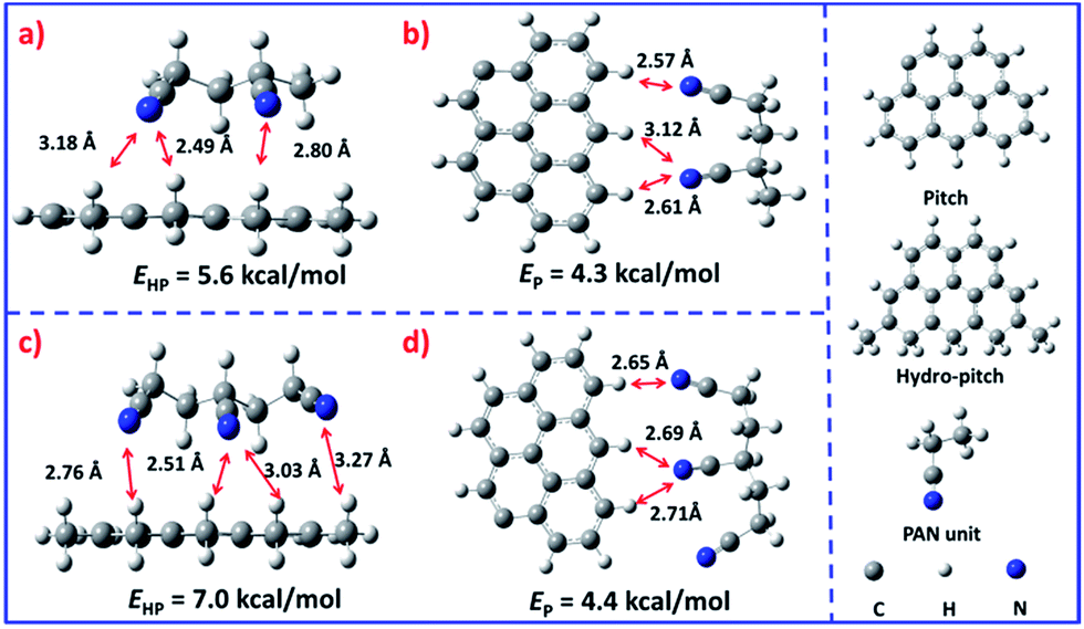 | ||
| Fig. 3 The spatial configurations and binding energies between two kinds of pitch molecules and PAN units. (a) Hydro-pitch with two PAN units, (b) molecular pitch and two PAN units, (c) hydro-pitch and three PAN units, (d) molecular pitch and three PAN units. | ||
The HCNF samples were also analyzed by X-ray photoelectron spectroscopy (XPS) and Raman spectra to reveal the changes in the surface configuration caused by the addition of hydro-pitch (Fig. S2, ESI†). Compared to PCNF (7.6 at%, Table S4, ESI†), sample 0.15-HCNF maintained 4.6 at% nitrogen content, and the same ID/IG ratio (1.07) was also obtained for the two samples. With an increase in hydro-pitch in the case of 1-HCNF, a slightly lower nitrogen content (4.2 at%) and ID/IG number (1.01) were observed, which could be attributed to the exposure of the hydro-pitch-based core, as mentioned in Fig. 1c. The XPS spectrum of N 1s is shown in Fig. S3 in the ESI† and the ratios of different nitrogen species are summarized in Table S5.† It is well known that these nitrogen species in the carbon network could produce highly electrocatalytically active sites,22,23 while the defects in carbon materials could also play the same role.
The HCNFs exhibited unique characteristics in which the shell retained the high nitrogen content and defects, while the core derived from hydro-pitch featured high conductivity. Such an integrated structure in one electrode is so attractive that it could be used as a high-performance CE in DSSCs, as shown in Scheme 1. In this case, it has great potential as an electrocatalyst for Pt replacement in DSSCs. Benefiting from this, the device performance for DSSCs with PCNF, Pt, and two HCNF CEs was determined and the results are shown in Table 1.
| Samples | Voc/V | Jsc/mA cm−2 | FF | η/% |
|---|---|---|---|---|
| 0.15-HCNF | 0.76 | 14.16 | 0.65 | 6.92 ± 0.15 |
| 1-HCNF | 0.75 | 13.48 | 0.63 | 6.32 ± 0.15 |
| PCNF | 0.76 | 12.25 | 0.46 | 4.26 ± 0.15 |
| Pt | 0.73 | 13.28 | 0.65 | 6.34 ± 0.15 |
As shown in Fig. 4a, our HCNF CEs exhibit similar or even better performance compared with Pt CE, and the electrochemical performance varies with the ratio of the hydro-pitch to PAN. The sample 0.15-HCNF CE shows a higher Jsc of 14.16 mA cm−2, a fill factor (FF) of 0.65 and a power conversion efficiency of 6.92%. In contrast, the Jsc, FF and power conversion efficiency (η) for the DSSCs with PCNF CE are only 12.25 mA cm−2, 0.46 and 4.26%, respectively; in particular, an increase in efficiency of 62.4% was observed. Nevertheless, when the ratio of hydro-pitch and PAN increased to 1, the performance of DSSCs with 1-HCNF electrode was reduced to Jsc of 13.48 mA cm−2, FF of 0.65 and η of 6.32%. The reason for this is attributed to the lower contents of nitrogen and defects, nitrogen and defects, and the loss of the Brunauer Emmet Teller (BET) surface (Table S6, ESI†).
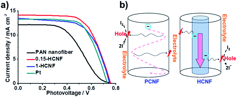 | ||
| Fig. 4 (a) Current density–voltage (J–V) characteristics with different CEs: PCNF, Pt, 1-HCNF, and 0.15-HCNF. (b) Illustration of charge transport and diffusion in different CNFs. | ||
To further demonstrate the unique effects of the coaxial CNF, to further demonstrate the unique effects of the coaxial CNF, the possible mechanism involved in the process was proposed and shown in Fig. 4b. As is known, the general consensus for the reaction mechanism can be described as follows:28
| I3− (sol) ↔ I2 (sol) + I− (sol) | (1) |
| I2 (sol) + 2* → 2I* | (2) |
| I* + e− → I− (sol) | (3) |
After the desorption of the solvated I− (sol) into the electrolyte, the activated site lost one electron and high-rate regeneration was demanded for the active site. The electrons from the external circuit are typically transferred from FTO to CE and then transmitted in CEs to the activated catalytic sites. The key in this process is the abundant supply of electrons to the activated sites within a short diffusion time. For our HCNF CE, the 1D tunnel structure minimizes the loss of electrons for its low electrical resistance, and high-rate regeneration of the active site is also realized by direct electron diffusion from the core to the activated catalytic site, due to its heterojunction structure. Benefiting from the unique structure, highly efficient utilization of the activated catalytic sites and fast charge transfer derived from short transport distance are achieved, and high power-conversion efficiency is yielded, which is comparable to or even better than other metal-free CEs reported in the literature (Table S8†).
To further investigate the electrochemical characteristics of HCNF CEs, Nyquist plots on an asymmetric dummy were obtained for Pt, PCNF and 0.15-HCNF electrodes (Fig. S4, ESI†).29 In contrast to Pt, both kinds of CNF CEs have the same lower Rs value, 1.6 Ω cm2 (Table S7, ESI†), indicating that good adhesion between CNFs and FTO was realized. High Rct values of 6.4 Ω cm2 for PCNF and 4.3 Ω cm2 for 0.15-HCNF CE (Table S7, ESI†) were also observed. In the future, further surface modification needs to be carried out to reduce the Rct value,17–19 thus optimizing and improving the electrochemical performance of CNFs.
In summary, the coaxial heterojunction CNFs with two phases were fabricated from PAN/hydro-pitch blend precursors using the electrospinning method, in which the shell and core were constructed by PAN based carbon and hydro-pitch based carbon, respectively. The as-made coaxial CNFs exhibited high conductivity derived from hydro-pitch, and high nitrogen content and defects derived from PAN. Such HCNFs were employed as CEs in DSSCs, and high power-conversion efficiencies were delivered, which are comparable to that of the Pt CE constructed under the same conditions. The tunnel along the axis direction separates the fibers into the charge transport phase and the electrocatalytic phase, and high utilization of catalytic sites is realized by the abundant charge supply and fast electron–hole recombination. In addition, this work shows that low cost and large-scale production of high performance CEs in DSSCs can be realized using the electrospinning method.
Conflicts of interest
There are no conflicts to declare.Acknowledgements
This work was partly supported by the NSFC of China (No. 21336001, 21522601), the Fundamental Research Funds for the Central Universities of China (DUT16ZD217), and the Education Department of the Liaoning Province of China (No. T2013001).References
- B. O. Oregan and M. Gratzel, Nature, 1991, 353, 737–781 CrossRef CAS.
- S. C. Hou, X. Cai, H. W. Wu, X. Yu, M. Peng and K. Yan, et al., Energy Environ. Sci., 2013, 6, 3356–3362 CAS.
- K. Imoto, K. Takahashi, T. Yamaguchi, T. Komura, J. I. Nakamura and K. Murata, Sol. Energy Mater. Sol. Cells, 2003, 79, 459–469 CrossRef CAS.
- R. R. Jia, J. Z. Chen, J. H. Zhao, J. F. Zheng, C. Song and L. Li, et al., J. Mater. Chem., 2010, 20, 10829–10834 RSC.
- Z. B. Yang, T. Chen, R. X. He, G. Z. Guan, H. P. Li and L. B. Qiu, et al., Adv. Mater., 2011, 23, 5436–5439 CrossRef CAS PubMed.
- J. Han, H. Kim, D. Y. Kim, S. M. Jo and S. Y. Jang, ACS Nano, 2010, 4, 3503–3509 CrossRef CAS PubMed.
- W. J. Lee, E. Ramasamy, D. Y. Lee and J. S. Song, ACS Appl. Mater. Interfaces, 2009, 1, 1145–1149 CAS.
- P. Dong, C. L. Pint, M. Hainey, F. Mirri, Y. J. Zhan and J. Zhang, et al., ACS Appl. Mater. Interfaces, 2011, 3, 3157–3161 CAS.
- G. Calogero, F. Bonaccorso, O. M. Marago, P. G. Gucciardi and G. Di Marco, Dalton Trans., 2010, 39, 2903–2909 RSC.
- H. Wang, K. Sun, F. Tao, D. J. Stacchiola and Y. H. Hu, Angew. Chem., Int. Ed., 2013, 52, 9210–9214 CrossRef CAS PubMed.
- J. D. Roy-Mayhew, D. J. Bozym, C. Punckt and I. A. Aksay, ACS Nano, 2010, 4, 6203–6211 CrossRef CAS PubMed.
- D. W. Zhang, X. D. Li, H. B. Li, S. Chen, Z. Sun and X. J. Yin, et al., Carbon, 2011, 49, 5382–5388 CrossRef CAS.
- L. Kavan, J. H. Yum and M. Gratzel, Nano Lett., 2011, 11, 5501–5506 CrossRef CAS PubMed.
- L. Kavan, J. H. Yum and M. Gratzel, ACS Nano, 2011, 5, 165–172 CrossRef CAS PubMed.
- G. Veerappan, K. Bojan and S. W. Rhee, ACS Appl. Mater. Interfaces, 2011, 3, 857–862 CAS.
- Y. H. Xue, J. Liu, H. Chen, R. G. Wang, D. Q. Li and J. Qu, et al., Angew. Chem., Int. Ed., 2012, 51, 12124–12127 CrossRef CAS PubMed.
- X. T. Meng, C. Yu, X. D. Song, Y. Liu, S. X. Liang and Z. Q. Liu, et al., Adv. Energy Mater., 2015, 5, 1500180 CrossRef.
- C. Yu, H. Q. Fang, Z. Q. Liu, H. Hu, X. T. Meng and J. S. Qiu, Nano Energy, 2016, 25, 184–192 CrossRef.
- H. Q. Fang, C. Yu, T. L. Ma and J. S. Qiu, Chem. Commun., 2014, 50, 3328–3330 RSC.
- X. Fang, Z. B. Yang, L. B. Qiu, H. Sun, S. W. Pan and J. Deng, et al., Adv. Mater., 2014, 26, 1694–1698 CrossRef CAS PubMed.
- I. Mochida, S. H. Yoon and Y. Korai, Chem. Rec., 2002, 2, 81–101 CrossRef CAS PubMed.
- K. P. Gong, F. Du, Z. H. Xia, M. Durstock and L. M. Dai, Science, 2009, 323, 760–764 CrossRef CAS PubMed.
- R. L. Liu, D. Q. Wu, X. L. Feng and K. Müllen, Angew. Chem., Int. Ed., 2010, 49, 2565–2569 CrossRef CAS PubMed.
- L. Y. Heng, A. Chou, J. Yu, Y. Chen and J. J. Gooding, Electrochem. Commun., 2005, 7, 1457–1462 CrossRef CAS.
- B. H. Kim, K. S. Yang, Y. A. Kim, Y. J. Kim, B. An and K. Oshida, J. Power Sources, 2011, 196, 10496–10501 CrossRef CAS.
- J. S. Travis and A. R. Horst, Biomaterials, 2008, 29, 1989–2006 CrossRef PubMed.
- S. Megelski, J. S. Stephens, D. B. Chase and J. F. Rabolt, Macromolecules, 2002, 35, 8456–8466 CrossRef CAS.
- Y. Hou, D. Wang, X. H. Yang, W. Q. Fang, B. Zhang and H. F. Wang, et al., Nat. Commun., 2013, 4, 1583 CrossRef PubMed.
- J. Z. Yin, Z. N. Yu, F. Gao, J. J. Wang, H. Pang and Q. Y. Lu, Angew. Chem., Int. Ed., 2010, 49, 6328–6332 CrossRef CAS PubMed.
Footnote |
| † Electronic supplementary information (ESI) available. See DOI: 10.1039/c7ra13118f |
| This journal is © The Royal Society of Chemistry 2018 |