 Open Access Article
Mechanism investigation on the reactions of ClF3O and n-decane by combining density functional theory and spontaneous emission spectroscopy†
Xinghua Liu a,
Hua Yana,
Daxi Wanga,
Yue Maa,
Shuyuan Li*a,
Yongfeng Luoa and
Shengli Xub
aCollege of Science, China University of Petroleum-Beijing, State Key Laboratory of Heavy Oil Processing, Beijing 102249, China. E-mail: syli@cup.edu.cn
bSchool of Aerospace Engineering, Tsinghua University, Beijing 100084, China
First published on 27th February 2018
Abstract
The mechanism of the reactions of ClF3O and n-decane had two stages. The first stage was the initial reaction between ClF3O and n-decane. The initial reactions were investigated using a density functional theory (DFT) method. The results showed that the critical part of the mechanism of the initial reaction was the roaming of the HF intermediate. A H atom on n-decane was abstracted by a F atom on ClF3O to produce HF. The formed HF roamed around and then broke to give ClFO, fluorinated decane and a new HF molecule. The initial reactions were considered to be barrier-less reactions and extremely exothermic. The average released energy of the initial reactions was 412.9 kJ mol−1, which was great enough to cause thermal decomposition of n-decane. The second stage included the reaction between ClFO and n-decane and the thermal decomposition of n-decane. The secondary reactions involving ClFO were also studied using a DFT method. ClFO was less reactive than ClF3O. The average energy barrier of the reactions of ClFO and n-decane was 116.3 kJ mol−1 and the average released energy was 266.5 kJ mol−1. Thermal decomposition of n-decane was evidenced by the emission spectra of the characteristic radical intermediates CH and C2, which were observed using an intensified charge-coupled device (ICCD) system. The main gaseous products of the thermal decomposition of n-decane, as identified using gas chromatography, were hydrogen, ethylene and acetylene. The experimental results showed that the thermal decomposition of n-decane was an important secondary reaction following the initial reactions.
1. Introduction
Halogen fluorides and their oxides are widely used as oxidizers, fluorinating agents, accelerators and initiators in the military and the semiconductor industry due to their unique chemical properties.1–4 Fundamental investigations of halogen fluorides and their oxidized derivatives, such as the study of the synthetic methods, crystal structures, spectra, thermodynamic properties and reactivity, have been conducted systematically since the 1960s.5–12 Halogen fluorides and their related oxides have extremely active chemical reactivity, and can react with fossil fuels violently. However, only a few studies focusing on the reaction mechanism have been reported. Brower et al. reported the reaction mechanism of ClF3 reacting with hydrocarbons. They proposed that this type of reaction followed an ionic mechanism, shown as reaction (1) in Scheme 1.1,13 A front-sided transition state was formed, and two fluorine atoms were consumed to give a fluorinated hydrocarbon and hydrogen fluoride. Niu et al.14 calculated the reaction pathways for ClF3O reacting with propane using DFT theory. They obtained nine different pathways that satisfied reaction eqn (2) in Scheme 1. ˙C3H7 and ˙ClF2O radicals were formed, showing that a free radical mechanism was involved. The average calculated energy barrier was about 8 kJ mol−1. This indicates that this reaction occurred readily at room temperature. Du et al.15 showed that the reactions between halogen fluorides and hydrocarbons were exothermic, and the released energy was sufficient to lead to the homolysis of C–C bonds on hydrocarbons. Baddiel et al.16 published a study about the mechanism for the reaction between ClF3 and methane. They concluded that a free radical chain mechanism was in operation for this reaction. A CH radical was involved as shown in Scheme 1 (reactions (3) and (4)). They also claimed that the mechanism was shared by other hydrocarbon pyrolytic processes. However, they didn’t demonstrate how ClF3 reacted with methane. To the best of our knowledge, the reaction mechanism between ClF3O and fossil fuels isn’t fully understood. In the present study, n-decane was chosen as a representative fossil fuel. The reaction of n-decane and ClF3O was studied using theoretical and experimental methods. DFT computation was employed to calculate the possible initiation pathways. An ICCD system was used to verify whether a radical mechanism was involved or not by detecting the appearance of CH and C2 radical intermediates. The aim of the present study is to obtain a better understanding of the reactions mentioned above. | ||
| Scheme 1 Previously reported reactions of halogen fluorides or their related oxides with hydrocarbons. | ||
2. Computational and experimental methods
2.1 Calculation methods
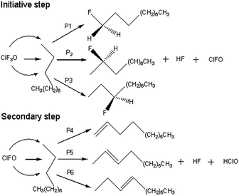
All of the calculated reaction pathways are shown in Scheme 2. ClF3O reacts with n-decane to give HF, ClFO and a corresponding fluorinated product. ClFO is an active intermediate and can abstract a hydrogen atom from n-decane to form HF, HClO and a corresponding alkene. For the ground state (the singlet state), all of the geometries of the reactants, transition states, intermediates and products were optimized using the B3PW91 method with a 6-31++G(d,p) basis set, which has been proven to be accurate enough for the current system.14,17 Frequency calculations were performed to verify that there was only one imaginary frequency for transition states and no imaginary frequency for the rest of the stationary states. Intrinsic reaction coordinate analysis (IRC) was employed to confirm the transition states connecting to the proper reactants and products.18,19 The excited state (the triplet state) computations were carried out at the UB3PW91/6-31++G(d,p) level of theory in order to examine the possibility of a radical mechanism. Enthalpies were calculated at the B3PW91/6-31++G(d,p) level of theory at 298.15 K and 0.2 MPa. The energy barrier was defined as the enthalpy difference between the transition state and the reactant. Similarly, the released energy was calculated from the enthalpy difference between the product and the reactant. All of the calculations were done using the Gaussian 03 program.202.2 Emission spectra determination
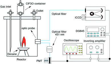
The experiments were performed in a 4 L stainless steel cylinder reactor. The diagram of the experimental setup is shown in Fig. 1. n-Decane (∼1.0 g, 99%, purchased from Tianjin chemical reagent factory) was placed in a crucible at the bottom of the reactor. ClF3O (∼0.1 g, 99%, purchased from Tianjin chemical reagent factory) was placed in a container at the top of the reactor. ClF3O could flow downwards onto the crucible through a tube and react with n-decane. The reaction would lead to chemiluminescent emissions, which were exported by two optics probes located 10 mm above the crucible on the side of the reactor wall. One fiber was connected to a time-gated 256-1024 element ICCD camera (Princeton Instruments) with a measuring range from 200 to 900 nm. The ICCD camera was coupled with a spectrometer (Acton spectra-Pro-275), which was calibrated using a mercury lamp. CH radical chemiluminescence was defined as the starting point of the thermal decomposition and was the trigger signal of the ICCD camera.21,22 Another fiber was connected with a 431 nm optical filter, and then the optical signal was transformed into an electric current (∼−50 mV) by a photomultiplier tube (PMT, Thorlabs), and the electric current was further amplified 100 times (∼5 V) by an inverting amplifier. Then a delay generator (DG645, Stanford research) and the ICCD were triggered sequentially. Hence, the emission spectra were recorded synchronously.2.3 Gaseous product determination
The gaseous products were passed through caustic soda solution to remove HF and other acidic gases and then analyzed using an Agilent 6890 GC System gas chromatograph, with a configuration of an HP-AL/S capillary column (25 m × 0.32 mm i.d. × 0.5 μm), a DM-PLOT 5A molecular sieve column (3 m × 4 mm i.d. × 180–250 μm) and a ProPark column (3 m × 4 mm i.d. × 150–180 μm). The flow of N2, H2 and air was 4 mL min−1, 40 mL min−1 and 300 mL min−1, respectively. The temperature of the inlet, FID detector and TCD detector was 250 °C. The programmed column temperature was elevated from 50 °C to 100 °C at a rate of 5 °C min−1, and then heated up to 180 °C at a heating rate of 10 °C min−1. The holding time was 3 min. Gaseous products including C1–C5 light hydrocarbons and inorganic gases were quantified using an external standard method. As reported previously,23,24 the relative error of quantities for gaseous products measured using this device was less than 0.5%.3. Results and discussion
3.1 Geometries
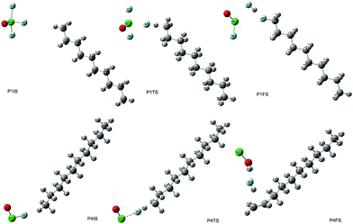
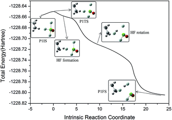
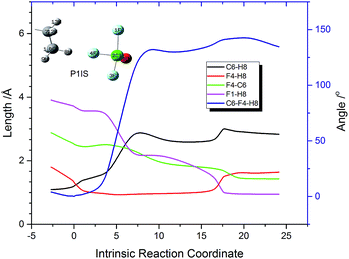
The initial geometric parameters of ClF3O were adopted from the electron diffraction data reported by Oberhammer,12 and then the geometry was fully optimized at the B3PW91/6-31++G(d,p) level. ClF3O has distorted trigonal bipyramidal geometry. The linear configuration of n-decane was employed and optimized at the same level of theory. The initial states (ISs), transition states (TSs) and final states (FSs) of different pathways can be found in the ESI.† Only the geometries of P1 are shown in Fig. 2. For the initiation stage, the related geometries of P1, P2 and P3 are similar, indicating that the position of the hydrogen atom is not an important factor for the reaction mechanism. Taking pathway P1 as an example, P1IS is the initial state of pathway P1, in which an F atom points towards an H atom on the methyl group at the end of n-decane. For the transition state P1TS, the corresponding Cl–F bond and C–H bond are elongated while the distance between H and F decreases. Meanwhile, the bond length of the other two Cl–F bonds also increases. In the final state P1FS, H is substituted by F to give 1-fluorodecane. Another F atom is consumed by H to yield HF. The third product of pathway P1 is ClFO. The geometry of P1TS is similar to that of P1IS, showing that this reaction is an exothermic process according to Hammond’s postulate.25 Not surprisingly, P1TS is totally geometrically different from P1FS.In order to interpret how P1IS transforms into P1FS, the related geometries along the IRC path of P1 are given in Fig. 3 and the related bond length and bond angle changes are plotted in Fig. 4. The transition state P1TS experiences two different steps, “HF formation” and “HF rotation”, before transforming into P1FS as shown in Fig. 3. In the “HF formation” step, HF is formed naturally from P1TS, but it is not the end of this reaction. Then the formed HF rotates around by itself. As a result, in the “HF rotation” step, F4 is approaching C6 and H8 is pointing to F1. In the geometry of P1FS, a new HF is formed while the original HF decomposes. As shown in Fig. 4, the length of F4–H8 decreases from 1.8 Å to 0.9 Å, which means that the H8–F4 bond is formed. Then the bond length keeps constant over the coordinate interval from coordinate 2 to coordinate 15, meanwhile the angle C6–F4–H8 increases rapidly and reaches 131° at coordinate 9. The increment of the angle C6–F4–H8 indicates the rotation of the HF molecule. The H8–F4 bond breaks gradually starting from coordinate 15, while the H8–F1 bond is formed at the same time. The distance of F4–C6 drops slowly along the reaction coordinate before the C6–F4 bond is formed at coordinate 20. The increasing trend of the bond length of C6–H8 shows that H8 is abstracted from the n-decane molecule by ClF3O. The interesting aspect of pathway P1 is the roaming of the H8F4 intermediate. It is the key to understanding the front-sided fluorinated reaction. Two F atoms are consumed in this process, which is consistent with the mechanism proposed by Brower.13
The reactions of ClFO and n-decane were also calculated with the aim of investigating the reactivity of ClFO. All of the corresponding geometries P4, P5 and P6 can be seen in S1.† Only the geometries of P4 are shown in Fig. 2. The reactions occurring via pathways P4, P5 and P6 are similar. Taking P4 as an example, the F atom continuously gets closer to the H atom on the methyl group while the C–H bond starts to break. Then the O atom keeps approaching the H atom on the adjacent methylene group. Therefore, two H atoms are abstracted by ClFO spontaneously to give HF and HClO, and a C![[double bond, length as m-dash]](https://www.rsc.org/images/entities/char_e001.gif) C double bond is generated by the loss of two hydrogen atoms.
C double bond is generated by the loss of two hydrogen atoms.
The F atom on ClF3O attacks the H atom on n-decane to initialize the reactions, and the formed HF intermediate roams and leads to substitution products for the initiation step. The secondary step belongs to an abstraction reaction. HF is the common product of the initiation reaction and the secondary reaction involving ClFO. The calculation results also state that the positions of the H atoms have no effect on the reaction mechanism.
3.2 Energetics
The energy profiles of the initiation step and the secondary step involving ClFO are summarized in Fig. 5. ClF3O is a highly reactive compound. The energy barrier of the initiation step is lower than 5 kJ mol−1. This shows that the initiation step can be considered as a barrier-less process. The average released energy for the initiation step is 412.9 kJ mol−1, which is greater than the bond dissociation energy of the C–C bond and C–H bond of n-decane.26 The energy differences among P1, P2 and P3 are very small. The general trend is that the closer the location of hydrogen to the chain terminal of n-decane, the greater the energy barrier is and the less the released energy is. This is because the C–H bond on the methyl group has more bond dissociation energy than other C–H bonds on n-decane.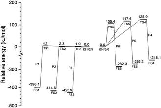 | ||
| Fig. 5 Energy profile of reaction pathways calculated at the B3PW91/6-31++G(d,p) level with ZPE correlation. | ||
The average value of the energy barrier for the secondary step involving ClFO is 116.3 kJ mol−1, which is much higher than that of the initiation step. The amount of released energy, with an average value of 266.5 kJ mol−1, is also smaller than the energy of the initiation step. Therefore, the reactivity of ClFO is much weaker than that of ClF3O. In addition, theoretically, the energy released during the initiation process can lead to thermal decomposition of n-decane. The thermal decomposition reactions compete with the secondary reactions involving ClFO. The possibility of the thermal decomposition of n-decane was further verified by the experimental results of spontaneous emission spectroscopy.
3.3 The excited state computation
Excited state computations were carried out to verify the radical mechanism. 38 points along the IRC of P1 in the ground state were selected. The excited state potential energy surfaces were calculated on the geometries of the ground state. The potential energy surfaces of the ground state and the excited state are shown in Fig. 6. It is clearly shown that the potential energy surface of the excited state is above that of the ground state, suggesting a non-radical mechanism.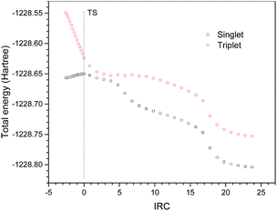 | ||
| Fig. 6 Singlet and triplet potential energy surfaces of selected points on the singlet geometries along IRC of P1. | ||
In addition, a relaxed potential energy surface scan was performed in the triplet state. The distance between the F atom on ClF3O and the H on the methyl group of n-decane was selected as the scan coordinate (the geometry is the same as that of P1IS). The distance decreased from 1.88 Å to 1.08 Å by the step size of −0.1 Å. The potential energy surface of the triplet state was obtained. Then the potential energy surface of the singlet state was calculated on the triplet geometries obtained using the relaxed potential energy surface scan. The potential energy surfaces of the triplet and singlet states were compared and are shown in Fig. 7. The results showed that the potential energy surface of the triplet state was above that of the singlet state. Therefore, the ground state pathway is a possible reaction channel, while the excited state pathway is energetically unfavorable.
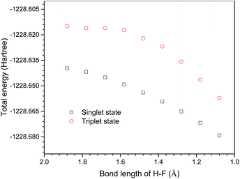 | ||
| Fig. 7 Singlet and triplet potential energy surfaces on triplet geometries produced by the relaxed potential energy surface scan. | ||
3.4 Emission spectra of C2, CH and OH radicals
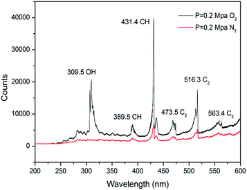
The emission spectra of n-decane/ClF3O in N2/O2 under 0.2 MPa at room temperature were obtained and are plotted in Fig. 8. Under the N2 atmosphere, the primary peak was found at 431 nm corresponding to the A2Δ–X2Π electronic transition of the CH radical.27 The peak at 516 nm produced by the A3Πg–X3Πu electronic transition of the C2 radical was also observed. The detection of the CH and C2 radical intermediates shows clearly that a large amount of energy is released during the process of the reaction between ClF3O and n-decane. The released energy breaks C–C and C–H bonds to produce CH and C2 radicals. The spectrum is consistent with the predictions of the DFT calculations. The initiation step is extremely exothermic. For the O2 atmosphere, the intensity of the spectrum is much stronger than that of the spectrum obtained under the N2 atmosphere. The intensity ratio of CHN2![[thin space (1/6-em)]](https://www.rsc.org/images/entities/char_2009.gif) :
:![[thin space (1/6-em)]](https://www.rsc.org/images/entities/char_2009.gif) CHO2 is about 1
CHO2 is about 1![[thin space (1/6-em)]](https://www.rsc.org/images/entities/char_2009.gif) :
:![[thin space (1/6-em)]](https://www.rsc.org/images/entities/char_2009.gif) 6. The new peak at 309 nm corresponds to the A2Σ+–X2Πi electronic transition of the OH radical. Small peaks at 389, 473 and 563 nm are attributed to CH, C2 and C2 radicals, respectively. CH and C2 radicals formed by the initiation step of the reactions of ClF3O and n-decane can react with O2 and then initialize combustion reactions. Consequently, ClF3O acts as an initiator in this process.
6. The new peak at 309 nm corresponds to the A2Σ+–X2Πi electronic transition of the OH radical. Small peaks at 389, 473 and 563 nm are attributed to CH, C2 and C2 radicals, respectively. CH and C2 radicals formed by the initiation step of the reactions of ClF3O and n-decane can react with O2 and then initialize combustion reactions. Consequently, ClF3O acts as an initiator in this process.
3.5 The gaseous product distribution
In order to further verify the occurrence of thermal decomposition in the process of the reactions of n-decane and ClF3O, the gaseous products were identified using gas chromatography. Besides HF, six gaseous products were found and their quantities are summarized in Fig. 9. It is worth noticing that the content of hydrogen accounts for around 50%, which is 2.5 times greater than that of the second most produced product ethylene. The formation of hydrogen is extremely endothermic and consumes more energy compared to the formation of other species, because C–H bonds need to break to form hydrogen molecules. According to the computational results, the first step of the reaction between ClF3O and n-decane releases 412.9 kJ mol−1 on average. The released energy can break C–H bonds easily. The amounts of propadiene and acetylene are over 10%, while the amounts of methane and ethane are less than 10%. The product distribution shows clearly that thermal decomposition takes place after the initiation step. Halohydrocarbons were not detected since most halohydrocarbons are liquid.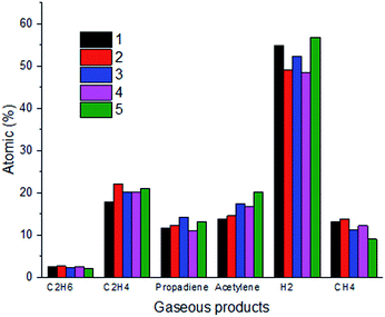 | ||
Fig. 9 Gaseous product distribution (the ratio of ClF3O to n-decane is 1![[thin space (1/6-em)]](https://www.rsc.org/images/entities/char_2009.gif) : :![[thin space (1/6-em)]](https://www.rsc.org/images/entities/char_2009.gif) 10, and five parallel experiments were conducted). 10, and five parallel experiments were conducted). | ||
4. Conclusions
Two stages, an initiation step and a secondary step, were determined for the process of the reactions of ClF3O and n-decane. A roaming mechanism was proposed for the initiation step. According to the IRC calculations, a HF molecule was formed at the beginning of the reaction, and then the H–F bond broke after rotating around to give ClFO, fluorinated decane and another new HF molecule. The initiation reactions were barrier-less and extremely exothermic. The average released energy of P1, P2 and P3 was 412.9 kJ mol−1. The radical mechanism was shown to be less likely by the excited state computation. The reactions of ClFO and n-decane and the thermal decomposition of n-decane were secondary reactions and competed with each other. ClFO was less reactive then ClF3O. It needed to absorb 116.3 kJ mol−1 to react with n-decane. The occurrence of thermal decomposition of n-decane was confirmed by the emission spectra and gaseous product distribution. The emission spectra of CH and C2 radical intermediates were observed. Hydrogen, ethylene and acetylene were the main gaseous products.Conflicts of interest
There are no conflicts to declare.Acknowledgements
This project was funded by the Special Projects of Taishan Scholar Construction Work (Grant No. ts20120518) and the China University of Petroleum (Beijing) Scientific Research Fund (Grant No. 2462015YQ0601). The authors thank Dr Yang Hu at the North China Institute of Science & Technology for the help with obtaining emission spectra.References
- A. Guber and U. Köhler, J. Mol. Struct., 1995, 348, 209 CrossRef CAS.
- Y. Saito, Sens. Mater., 2002, 14, 231 CAS.
- C. J. Gugliemini and A. D. Johnson, Semicond. Int., 1999, 22, 1 Search PubMed.
- A. Pierce, M. Taylor, J. Sauer and D. Ruppert, Solid State Technol., 1997, 40, 107 CAS.
- D. Pilipovich, C. B. Lindahl, C. J. Schack, R. D. Wilson and K. O. Christe, Inorg. Chem., 1972, 11, 2189 CrossRef CAS.
- D. Pilipovich, H. H. Rogers and R. D. Wilson, Inorg. Chem., 1972, 11, 2192 CrossRef CAS.
- K. O. Christe and E. C. Curtis, Inorg. Chem., 1972, 11, 2196 CrossRef CAS.
- C. J. Schack, C. B. Lindahl, D. Pilipovich and K. O. Christe, Inorg. Chem., 1972, 11, 2201 CrossRef CAS.
- K. O. Christe, C. J. Schack and D. Pilipovich, Inorg. Chem., 1972, 11, 2205 CrossRef CAS.
- K. O. Christe and E. C. Curtis, Inorg. Chem., 1972, 11, 2209 CrossRef CAS.
- K. O. Christe, E. C. Curtis and C. J. Schack, Inorg. Chem., 1972, 11, 2212 CrossRef CAS.
- H. Oberhammer and K. O. Christe, Inorg. Chem., 1982, 21, 273 CrossRef CAS.
- K. R. Brower, J. Fluorine Chem., 1986, 31, 333 CrossRef CAS.
- L. Niu, Z. Liu, S. Wang, Y. Luo and X. Sun, Acta Chim. Sin., 2010, 68, 1787 CAS.
- H. Du, G. Wang, X. Gong and H. Xiao, Int. J. Quantum Chem., 2012, 112, 1291 CrossRef CAS.
- C. B. Baddiel and C. F. Cullis, Symp. Combust., 1961, 8, 1089 CrossRef.
- H. Yan, Y. F. Luo, H. Q. Gao, P. Yan and K. S. Luo, Chin. J. Energ. Mater., 2015, 23, 346 Search PubMed.
- C. Gonzalez and H. B. Schlegel, J. Chem. Phys., 1989, 90, 2154 CrossRef CAS.
- C. Gonzalez and H. B. Schlegel, J. Phys. Chem., 1990, 94, 5523 CrossRef CAS.
- M. J. Frisch, G. W. Trucks, H. B. Schlegel, G. E. Scuseria, M. A. Robb, J. R. Cheeseman, J. A. Montgomery, T. Vreven, K. N. Kudin, J. C. Burant, J. M. Millam, S. S. Iyengar, J. Tomasi, V. Barone, B. Mennucci, M. Cossi, G. Scalmani, N. Rega, G. A. Petersson, H. Nakatsuji, M. Hada, M. Ehara, K. Toyota, R. Fukuda, J. Hasegawa, M. Ishida, T. Nakajima, Y. Honda, O. Kitao, H. Nakai, M. Klene, X. Li, J. E. Knox, H. P. Hratchian, J. B. Cross, V. Bakken, C. Adamo, J. Jaramillo, R. Gomperts, R. E. Stratmann, O. Yazyev, A. J. Austin, R. Cammi, C. Pomelli, J. W. Ochterski, P. Y. Ayala, K. Morokuma, G. A. Voth, P. Salvador, J. J. Dannenberg, V. G. Zakrzewski, S. Dapprich, A. D. Daniels, M. C. Strain, O. Farkas, D. K. Malick, A. D. Rabuck, K. Raghavachari, J. B. Foresman, J. V. Ortiz, Q. Cui, A. G. Baboul, S. Clifford, J. Cioslowski, B. B. Stefanov, G. Liu, A. Liashenko, P. Piskorz, I. Komaromi, R. L. Martin, D. J. Fox, T. Keith, A. Laham, C. Y. Peng, A. Nanayakkara, M. Challacombe, P. M. W. Gill, B. Johnson, W. Chen, M. W. Wong, C. Gonzalez and J. A. Pople, Gaussian 03, Revision C.02 Search PubMed.
- C. Zhang, P. Li, J. Guo and X. Li, Energy Fuels, 2012, 26, 1107 CrossRef CAS.
- C. Zhang, H. Tang, C. Zhang, Y. Zhao, P. Li and X. Li, Chem. Phys. Lett., 2013, 556, 13 CrossRef CAS.
- J. Shi, Y. Ma, S. Li, J. Wu, Y. Zhu and J. Teng, Energy Fuels, 2017, 31, 4808 CrossRef CAS.
- J. Shi, Y. Ma, S. Li and L. Zhang, Energy Fuels, 2017, 31, 10535 CrossRef CAS.
- G. S. Hammond, J. Am. Chem. Soc., 1955, 77, 334 CrossRef CAS.
- Y. Xiao, J. M. Longo, G. B. Hieshima and R. J. Hill, Ind. Eng. Chem. Res., 1997, 36, 4033 CrossRef CAS.
- R. Bleekrode and W. C. Nieuwpoort, J. Chem. Phys., 1965, 43, 3680 CrossRef CAS.
Footnote |
| † Electronic supplementary information (ESI) available. See DOI: 10.1039/c7ra13092a |
| This journal is © The Royal Society of Chemistry 2018 |

