 Open Access Article
Creative Commons Attribution 3.0 Unported Licence
Ti surface doping of LiNi0.5Mn1.5O4−δ positive electrodes for lithium ion batteries†
F. Ulu Okudur a,
J. D'Haenb,
T. Vranken
 a,
D. De Sloovere
 a,
M. Verheijena,
O. M. Karakulina
 c,
A. M. Abakumovcd,
J. Hadermannc,
M. K. Van Bael
 a and
A. Hardy*a
aUHasselt, Institute for Materials Research (IMO-IMOMEC), Partner in Energyville, Inorganic and Physical Chemistry, Agoralaan, 3590 Diepenbeek, Belgium. E-mail: an.hardy@uhasselt.be
bUHasselt, Institute for Materials Research (IMO-IMOMEC), Materials Physics, Wetenschapspark 1, 3590 Diepenbeek, Belgium
cEMAT, University of Antwerp, Groenenborgerlaan 171, B-2020 Belgium
dSkoltech Center for Electrochemical Energy Storage, Skolkovo Institute of Science and Technology, Nobel Str. 3, 143026 Moscow, Russia
First published on 13th February 2018
Abstract
The particle surface of LiNi0.5Mn1.5O4−δ (LNMO), a Li-ion battery cathode material, has been modified by Ti cation doping through a hydrolysis–condensation reaction followed by annealing in oxygen. The effect of different annealing temperatures (500–850 °C) on the Ti distribution and electrochemical performance of the surface modified LNMO was investigated. Ti cations diffuse from the preformed amorphous ‘TiOx’ layer into the LNMO surface during annealing at 500 °C. This results in a 2–4 nm thick Ti-rich spinel surface having lower Mn and Ni content compared to the core of the LNMO particles, which was observed with scanning transmission electron microscopy coupled with compositional EDX mapping. An increase in the annealing temperature promotes the formation of a Ti bulk doped LiNi(0.5−w)Mn(1.5+w)−tTitO4 phase and Ti-rich LiNi0.5Mn1.5−yTiyO4 segregates above 750 °C. Fourier-transform infrared spectrometry indicates increasing Ni–Mn ordering with annealing temperature, for both bare and surface modified LNMO. Ti surface modified LNMO annealed at 500 °C shows a superior cyclic stability, coulombic efficiency and rate performance compared to bare LNMO annealed at 500 °C when cycled at 3.4–4.9 V vs. Li/Li+. The improvements are probably due to suppressed Ni and Mn dissolution with Ti surface doping.
Introduction
High energy and power density lithium ion batteries (LIB) are extensively studied for their potential applications in portable electronics, hybrid/full electric vehicles as well as for their ability to store solar, wind and other types of renewable energy with high efficiency.1–4 Special attention is directed towards electric vehicle research to replace internal combustion engine vehicles to reduce greenhouse gas emissions.1,5 Nowadays, LiCoO2 is commercially used as a positive electrode (cathode) in LIB for many applications.2,4 However, it has a low thermal stability and moreover, cobalt is both toxic and expensive.1 Finding a less expensive material, e.g. based on manganese, helps reduce the LIB production cost and increase its role in renewable energy applications.1,6LiMn2O4 (LMO) has a spinel crystal structure containing mixed-valence Mn4+ and Mn3+, with an average oxidation state of +3.5.7 The Mn3+/4+ redox reaction is known to take place at the 4.1 V plateau vs. Li/Li+ during charge/discharge. LMO has the tendency to form oxygen vacancies during high temperature synthesis. Once formed, the oxygen vacancies increase the fraction of Mn3+, which, prone to the Jahn–Teller effect, induces lattice expansion and collapse of the structure.8 The crystal structure of LMO can be stabilized by substituting Ni2+ for Mn3.5+, since this increases the average Mn oxidation state. Ni2+ substitution results in the LiNixMn2−xO4−δ (LNMO) phase, with a second voltage plateau at 4.7 V corresponding to the Ni2+/4+ redox reaction.9 This plateau becomes longer as the concentration of Ni2+ in LNMO increases, while the Mn3/4+ plateau at 4.1 V becomes shorter.9 In the stoichiometric LiNi0.5Mn1.5O4 (x = 0.5), all Mn remains in its 4+ oxidation state upon cycling and all the energy is stored through Ni redox reactions at a single long 4.7 V plateau. LiNi0.5Mn1.5O4 therefore attracts attention as a high voltage cathode material (4.7 V vs. Li/Li+) with a good capacity (147 mA h g−1) having potential for high power applications.10,11
LiNi0.5Mn1.5O4 has two crystalline forms with different degree of ordering of Ni and Mn.12,13 In the disordered Fd![[3 with combining macron]](https://www.rsc.org/images/entities/char_0033_0304.gif) m type LNMO Ni and Mn randomly occupy the 16d site.14,15 On the other hand, in the fully ordered P4332 type LNMO, Ni and Mn reside separately in the 4b and 12d sites, respectively. Formation of the two different crystalline forms is mainly caused by the oxygen evolution reaction and oxygen vacancy formation during anneal. This causes formation of the larger Mn3+ cations in comparison to the Mn4+, which lead to formation of the disordered LNMO. The structure is influenced by annealing temperature, atmosphere and heating/cooling rates.12,16 A mixture of the two can be present as well, defined as LNMO with partial ordering.17
m type LNMO Ni and Mn randomly occupy the 16d site.14,15 On the other hand, in the fully ordered P4332 type LNMO, Ni and Mn reside separately in the 4b and 12d sites, respectively. Formation of the two different crystalline forms is mainly caused by the oxygen evolution reaction and oxygen vacancy formation during anneal. This causes formation of the larger Mn3+ cations in comparison to the Mn4+, which lead to formation of the disordered LNMO. The structure is influenced by annealing temperature, atmosphere and heating/cooling rates.12,16 A mixture of the two can be present as well, defined as LNMO with partial ordering.17
The cyclic stability of LNMO still remains an issue since all cathode materials containing Mn are challenged with a capacity fade problem due to Mn leaching into commercial electrolytes, during cycling or storage.1,18 The Mn leaching is explained by two different mechanisms: the disproportionation reaction at lower potentials and the acid dissolution at medium to high charged states.18 The Mn3+ presence in non-stoichiometric LiNi0.5Mn1.5O4−δ may cause Mn2+ formation through the following disproportionation reaction:
| 2Mnsolid3+ → Mnsolid4+ + Mnsolution2+ | (1) |
Mn2+ dissolves in the electrolyte, while Mn4+ remains in the solid. Continuous Mn2+ dissolution at the cathode, in combination with a deposition of this Mn2+ as metallic Mn at the anode, destabilizes the anode solid electrolyte interface (SEI).19 This causes increase of the SEI thickness, irreversible Li+ loss and capacity fade in Li-ion full cells, especially with carbon based anodes.1,18 The second Mn loss mechanism is by hydrofluoric acid corrosion. HF forms by hydrolysis of LiPF6 salt in electrolyte in presence of protonic impurities or traces of water.18 LNMO cathode systems are also challenged with a major electrolyte stability problem at high voltages.20 A surface layer forms on the cathode–electrolyte interface (CEI), due to electrolyte oxidation reactions at high potentials.21 The thickness of this non-conducting19,20 layer increases during cycling, causing an increase in impedance and capacity fade, especially at higher temperatures.20,22,23
Introducing a protective shell on LNMO that is stable at high voltages can prevent Mn dissolution and increase cycle life. It will also enable good conductivity if the shell is ionically and electronically conductive.18,22,24–27 Hao et al.22 reported Li4Ti5O12 (LTO) and TiO2 coatings to effectively reduce the LNMO capacity fade. However, both shell materials provided lower rate performances compared to bare samples, which was explained by low electrical conductivity of TiO2 and LTO. As an alternative approach to shell deposition on core materials to suppress Mn dissolution, Lu et al. proposed the Ti cation surface doping concept for surface protection of LiMn2O4 (LMO) particles without altering the spinel surface structure.28 They compared Ti surface-doped LMO nanopowders to TiO2 surface-coated LMO nanopowders synthesized via sol–gel and atomic layer deposition (ALD) techniques, respectively. The surface-doped LiMn2O4 powders synthesized via sol–gel demonstrate a better cyclic stability, electrical and ionic conductivity, compared to TiO2 coated LiMn2O4 synthesized via ALD.28 A similar Ti surface doping approach was recently reported by Wang et al. for LNMO via solid-state synthesis using TiO2 under a flow of air.23 Ti doping took place within a 1–3 nm thick LNMO surface, forming a rocksalt-like structure on the LNMO surface. The rocksalt-like structure was discussed to be a possible blockage for the transfer of Li-ions within the first cycle. Ti surface modification showed no significant improvement on rate performance, cycle life or coulombic efficiency at 25 °C. However, much better capacity retention and coulombic efficiencies were obtained with 55 °C cycling.23
In this work, we use a hydrolysis–condensation approach to homogeneously modify the LNMO surface with Ti cation, maintaining the spinel surface structure. Since excessive Ti doping at the core may cause capacity loss,29 we investigate the effect of different annealing temperatures (500–850 °C) on Ti diffusion from the surface of LNMO towards the core. Furthermore, we examine the combined effects of annealing temperature, spatial Ti distribution, (dis)order of Ni–Mn ions and particle size on the electrochemical performance.
Experimental
Material synthesis
Commercial LiNi0.5Mn1.5O4−δ (LNMO) nanoparticles (Sigma-Aldrich, <500 nm, >99%), also referred to as the ‘bare LNMO’, were used as core material. Bare LNMO powder was annealed at temperatures ranging from 500 to 850 °C for better comparison with the surface modified LNMO, also annealed at temperatures ranging from 500 to 850 °C. The surface modification method reported here is based on TiO2 coating made for calcite, α-Fe2O3, Fe3O4, SiO2, graphene oxide and carbon as core materials.30,31 Hydrolysis and condensation reactions of titanium butoxide (TBOT, Aldrich, reagent grade 97%) were catalyzed by NH3 (Merck, EMSURE, 25 wt% ammonia solution). 3 g of LNMO as received, was dispersed in 20 mL absolute ethanol (Merck, EMSURE ACS, ISO, Reag. Ph. Eur for analysis) at 25 °C and sonicated for ∼15 minutes in a bath sonicator (Branson, 3510). The dispersion was then added into 80 mL absolute ethanol at 45 °C, under reflux setup, and stirred using a magnetic stirrer bar at 500 rpm. 0.5 mL NH3 was added into the suspension. 12 mL TBOT was mixed with 8 mL absolute ethanol. The TBOT–ethanol mixture was added dropwise into the prepared LNMO–NH3 ethanol dispersion using an autotitrator (Schott Gerate, T100, TA20) at a rate of 1.43 mL h.30 Reactions took place at 45 °C, under a closed N2 setup (Air Liquide, Alphagaz 1). The total reaction time was ∼20 hours. After synthesis, the powder was collected through centrifuging (Eppendorf, 5804R) at 14![[thin space (1/6-em)]](https://www.rsc.org/images/entities/char_2009.gif) 000g for 5 min and washed-centrifuged 3 times with absolute ethanol for 30 min each. Powders were then left to dry overnight at room temperature and ambient atmosphere. Anneals were performed for both bare and surface modified samples at temperatures ranging from 500 to 850 °C, in a tube furnace under O2 flow (Air Liquide, Alphagaz Ind.) for only 2 hours to avoid excessive Ti diffusion from surface to core. Heating and cooling rates were 1° min−1, corresponding to a total annealing time of 20 to 30 h including the heating and cooling intervals, for annealing temperatures ranging from 500 to 850 °C. Surface modified LNMO powders from the same synthesis experiment were used for all anneals.
000g for 5 min and washed-centrifuged 3 times with absolute ethanol for 30 min each. Powders were then left to dry overnight at room temperature and ambient atmosphere. Anneals were performed for both bare and surface modified samples at temperatures ranging from 500 to 850 °C, in a tube furnace under O2 flow (Air Liquide, Alphagaz Ind.) for only 2 hours to avoid excessive Ti diffusion from surface to core. Heating and cooling rates were 1° min−1, corresponding to a total annealing time of 20 to 30 h including the heating and cooling intervals, for annealing temperatures ranging from 500 to 850 °C. Surface modified LNMO powders from the same synthesis experiment were used for all anneals.
Material characterization
Zeta potential measurements (Brookhaven Instruments, ZetaPALS/90Plus) were carried out for bare LNMO–ethanol dispersions. 5 mL of the sample was taken from a sonicated suspension of 3 g LNMO in 100 mL ethanol, both before and after 0.5 mL NH3 addition. The samples were centrifuged at 4000g for 2 minutes and the supernatants were collected for zeta-potential measurements. The Hückel approximation was used and the f(Ka) value was taken as 1.0 due to the low dielectric constant of ethanol media.32 pH measurements in the ethanol media were made according to ASTM standard on pHe determination using a HI 3223 pH meter and water-based HI 1131 electrode.33 Thermogravimetric analysis was carried out by means of a Q600 TA Instrument TGA coupled with differential scanning calorimetry (TGA-DSC) from 22 to 800 °C with a heating rate of 10° min−1 under dry air flow. The LNMO particle size distribution and morphology were determined using scanning electron microscopy (SEM, FEI Quanta 200F) and transmission electron microscopy (TEM, FEI Tecnai G2 Spirit Twin, 120 kV). ImageJ software was used for data analysis.34 TEM samples were prepared by dispersing powder in absolute ethanol, sonicating for ∼30 seconds, dropping onto carbon coated copper grids (EMS, FCF-200-Cu) and drying under an infrared lamp for several minutes. The high angle annular dark field (HAADF) scanning TEM (STEM) imaging was performed at a FEI Osiris (200 kV) and FEI Titan G3 microscopes (200 and 300 kV). A Super-X detector was used for the energy dispersive X-ray mapping in a STEM mode (STEM-EDX). The powder X-ray diffraction (XRD) patterns were recorded with a Bruker AXS D8 Discover diffractometer (Cu Kα radiation (λ = 1.5418 Å), 0.02° 2θ step, LynxEye detector). The lattice parameter refinements were carried out using the GSAS-EXPGUI software.35,36 The calibration of the diffractometer constants were done using LaB6 powder (Alfa Aesar, 99.5%). Fourier transformed infrared spectroscopy (FTIR) was performed on a Bruker Vertex 70 spectrometer from 4000 to 400 cm−1, with 32 scans and 4 cm−1 resolution. Pellets containing trace amounts of the sample and 300 mg KBr were prepared by milling in a mortar and pressing under 3 tons for 1.5 minutes. Brunauer–Emmett–Teller (BET) measurements (QuadraSorb SI MP) were made based on N2 adsorption at 77 K to determine the surface areas. Samples were degassed at 300 °C for 16 h before measurements.Coin cells containing Li metal (Sigma-Aldrich), Celgard 2400 separator, working electrode and 1.0 M LiPF6 EC/DMC (1![[thin space (1/6-em)]](https://www.rsc.org/images/entities/char_2009.gif) :
:![[thin space (1/6-em)]](https://www.rsc.org/images/entities/char_2009.gif) 1, v/v) electrolyte (Soulbrain) were constructed in an argon glovebox. Working electrodes were prepared by ball-milling of 80 wt% LNMO or surface modified LNMO active material, 10 wt% carbon black (Timcal-imerys c-nergy super C-65) and 10 wt% PVDF (Alfa Aesar, 44080) dissolved in NMP (Alfa Aesar, ACS grade, 99.0+%). The mixture was spread on an aluminum current collector foil by Doctor Blade method (MTI, MSK-AFA-II) after which the foil was dried in a vacuum furnace. Electrode punches of about 3 to 4 mg cm−2 loading were made and 1 ton pressure was applied on each for about a second (15 to 20 ìm thickness after drying and aluminum current collector foil thickness subtraction from the total electrode punch thickness). Coin cells were rested for 5 days before measurements. Galvanostatic charge–discharge measurements were performed in 3.4 to 4.9 V voltage window at 0.5 C rate for 200 cycles using a Bio-Logic BCS-805 battery tester. Rate performance measurements were performed within the 0.05 to 2 C rate interval.
1, v/v) electrolyte (Soulbrain) were constructed in an argon glovebox. Working electrodes were prepared by ball-milling of 80 wt% LNMO or surface modified LNMO active material, 10 wt% carbon black (Timcal-imerys c-nergy super C-65) and 10 wt% PVDF (Alfa Aesar, 44080) dissolved in NMP (Alfa Aesar, ACS grade, 99.0+%). The mixture was spread on an aluminum current collector foil by Doctor Blade method (MTI, MSK-AFA-II) after which the foil was dried in a vacuum furnace. Electrode punches of about 3 to 4 mg cm−2 loading were made and 1 ton pressure was applied on each for about a second (15 to 20 ìm thickness after drying and aluminum current collector foil thickness subtraction from the total electrode punch thickness). Coin cells were rested for 5 days before measurements. Galvanostatic charge–discharge measurements were performed in 3.4 to 4.9 V voltage window at 0.5 C rate for 200 cycles using a Bio-Logic BCS-805 battery tester. Rate performance measurements were performed within the 0.05 to 2 C rate interval.
Results and discussion
LNMO surface modification mechanism
Ti(OBu)4 (TBOT) is used as the Ti4+ source during synthesis. TBOT is soluble in ethanol and many other organic solvents, but reacts with even traces of water through fast hydrolysis and condensation reactions leading to homogeneous nucleation of solid amorphous TiOx,31 whereas for LNMO surface modification only heterogeneous nucleation is desirable. So, low hydrolysis rates are aimed at in order to obtain uniform amorphous TiOx surface modifications and to prevent secondary homogeneous nucleation of amorphous TiOx. Longer alkyl groups in the alkoxide reduce the partial positive charge on the Ti(IV)-centre and hence lower the hydrolysis rate.37 However, here, reaction rates were adjusted by adding 0.5 mL of aqueous NH3 acting as a catalyst, in order to control amorphous TiOx nucleation at the surface of the core LNMO particles31 and to modify a thin layer of the LNMO surface.31 A slow TBOT addition rate furthermore provides enough time for the hydrolyzed molecular precursor to diffuse to the surface of the LNMO particles.30Zeta-potential measurements were performed in ethanol surface modification medium to observe the effect of the NH3 addition. Results of these measurements are shown in Table 1. NH3 addition converts the negative LNMO surface charge to a positive one by the adsorption of NH4+. The zeta potential of titania in ethanol, on the other hand, was reported to be negative between pH* values of about 5 and 11 (pH* being the operational ‘pH’ measured in ethanol using an ordinary glass electrode with a Ag/AgCl reference electrode in saturated LiCl–ethanol electrolyte).38 This probably leads to an electrostatic attraction between negatively charged amorphous TiOx species and positively charged LNMO core particles. Wang et al.39 used a similar in situ hydrolysis/condensation based technique to coat polystyrene (PS) nanoparticles with titania and suggested a coating mechanism based mainly on electrostatic attraction. According to this theory, positively charged NH4+ species are formed and adsorbed on the surface of the negatively charged core PS nanoparticles. The negatively charged hydrolysates of TBOT, (C4H9OH)3TiO−, formed in the presence of NH3 are then attracted to the core nanoparticle surface by electrostatic attraction between these adsorbed NH4+ species and titania species. Consequently; condensation reactions, catalyzed by the adsorbed NH4+, take place at the surface. We propose a similar surface modification mechanism taking place here.
| Sample | pH | Mean zeta-potential (mV) | ±Error |
|---|---|---|---|
| Before 0.5 mL NH3 (25 wt%) addition | 9.3 | −10.8 | 0.6 |
| After 0.5 mL NH3 (25 wt%) addition | 10.9 | +17.8 | 1.8 |
Material properties at different annealing temperatures
![[thin space (1/6-em)]](https://www.rsc.org/images/entities/char_2009.gif) :
:![[thin space (1/6-em)]](https://www.rsc.org/images/entities/char_2009.gif) Ni
Ni![[thin space (1/6-em)]](https://www.rsc.org/images/entities/char_2009.gif) :
:![[thin space (1/6-em)]](https://www.rsc.org/images/entities/char_2009.gif) Mn ratios were found to be close to 0.9
Mn ratios were found to be close to 0.9![[thin space (1/6-em)]](https://www.rsc.org/images/entities/char_2009.gif) :
:![[thin space (1/6-em)]](https://www.rsc.org/images/entities/char_2009.gif) 0.5
0.5![[thin space (1/6-em)]](https://www.rsc.org/images/entities/char_2009.gif) :
:![[thin space (1/6-em)]](https://www.rsc.org/images/entities/char_2009.gif) 1.5, indicating an overall agreement with the stoichiometric LiNi0.5Mn1.5O4 formula, while the Li content was slightly lower than the nominal one.
1.5, indicating an overall agreement with the stoichiometric LiNi0.5Mn1.5O4 formula, while the Li content was slightly lower than the nominal one.
Weight losses due to oxygen evolution can also be observed for the Ti surface modified LNMO, prior to anneal in Fig. 2(b), at temperatures above 700 °C. Two exothermic heat flow peaks at about 250 and 450 °C in Fig. 2(b) are accompanied by weight losses. The DSC curve for amorphous TiOx in Fig. 2(c) has similar exothermic heat flow peaks. The two peaks at 250 and 450 °C temperatures are probably an indication of evaporation and combustion of organic compounds or water being released from the unreacted hydroxyl groups.41 Based on these results, the minimum annealing temperature was chosen to be 500 °C, in order to remove the organic remains. 850 °C was chosen as the maximum temperature, which is above the oxygen evolution temperature of 700 °C. This allows us to investigate the influence of the oxygen evolution on the crystal structure and battery performance. An oxygen atmosphere was used during all anneals, in order to minimize the initial capacity loss caused by the formation of LizNi1−zO impurities in oxygen poor ambients.42
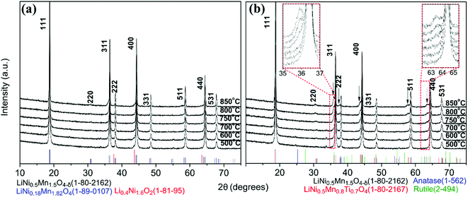
The XRD patterns of surface modified samples (Fig. 3(b)) show that the LNMO spinel structure was preserved. Secondary phases form in the surface modified LNMO samples at and above 750 °C, which is indicated by the arrows in Fig. 3(b). Following oxygen evolution reaction is proposed for annealing at and above 750 °C, similar to the one proposed by Le et al.:43
| LiNi0.5Mn1.5O4 + aTiOx(amorp.) → bLiNi0.5Mn1.5−yTiyO4 + cLizNi1−zO + dLiNi(0.5−w)Mn(1.5+w)−tTitO4 + eO2 | (2) |
Based on this reaction, the secondary phase peaks in the XRD can be attributed to a combination of three different phases having similar peak positions: the spinel LiNi0.5Mn1.5−yTiyO4 (e.g. LiNi0.5Mn0.8Ti0.7O4, JCPDS/ICDD 01-080-2167)44–46 and the Mn-rich spinel LiNi(0.5−w)Mn(1.5+w)−tTitO4 (ref. 43) phases formed by replacement of Mn3/4+ with Ti4+ and the rock-salt LizNi1−zO impurity phase, formed because of oxygen deficiency. Further discussion on composition of these secondary phases is made in the TEM part.
The lattice parameters of bare and surface modified samples annealed between 500 and 850 °C (Table S3, Fig. S7†47) show no significant difference. (HR)STEM was performed for the surface modified samples with 500, 800 and 850 °C anneals to estimate the Ti content and clarify the Ti location in the sample.
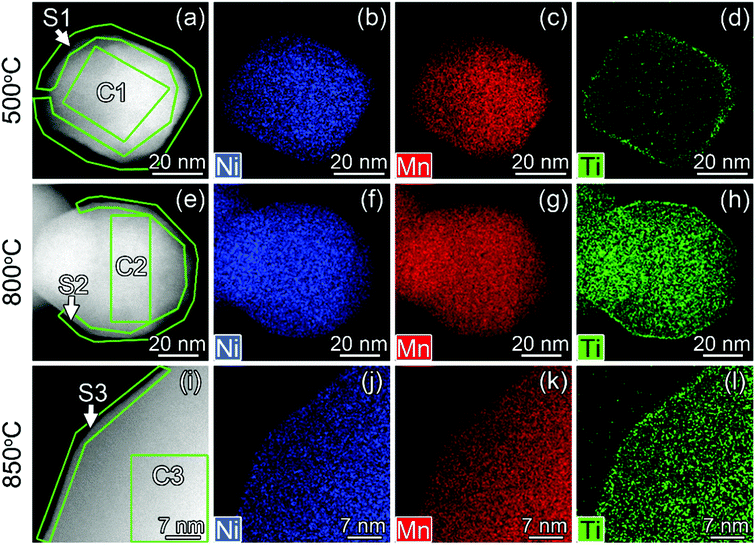 | ||
| Fig. 4 HAADF-STEM images (a, e and i) and STEM-EDX maps of Ni, Mn and Ti for Ti surface-modified LNMO particles annealed at 500 (a–d), 800 (e–h) and 850 °C (i–l). The elemental contents for the marked region are shown in Fig. 5. ‘C’ and ‘S’ stand for ‘core’ and ‘surface’. | ||
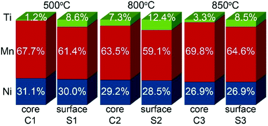 | ||
| Fig. 5 Ni, Mn and Ti contents in atomic% for regions shown in Fig. 4. | ||
In surface modified LNMO-500 °C, the Ti is mainly present in the surface layer of the LNMO particles (Fig. 6(a)). Only a few Ti-rich impurity particles were noticed. A Ti-containing secondary phase was not observed in the XRD pattern of this sample, probably because the peaks corresponding to the 2–4 nm thick surface layers are too broad and not within the detection limits of powder XRD, or the scattering amount of the Ti modified surface is too small compared to the core of the nanopowders so that possible peaks become hardly detectable. However, Ti-rich particles of about 200 nm and 0.5–1 μm were observed at 800 °C and 850 °C, respectively (Fig. 6(b and c)), which could be attributed to the sharp, secondary phase peaks in their XRDs. The average elemental composition of these Ti-rich particles was estimated for the surface modified LNMO-850 °C (Table 2). Ni content is same as expected for the stoichiometric LiNi0.5Mn1.5O4−δ phase, but the Mn content is lower, resulting in LiNi0.5Mn1.5−yTiyO4 formula. On the other hand, the majority of the particles contains ∼1 at% of Ti and has lower Ni but higher Mn content compared to the stoichiometric LiNi0.5Mn1.5O4−δ. These low Ti content particles can be identified as a Ti bulk doped, LiNi(0.5−w)Mn(1.5+w)−tTitO4 phase.
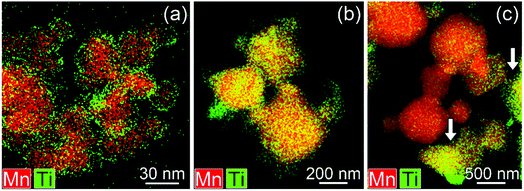 | ||
| Fig. 6 Mixed (Mn, Ti) STEM-EDX maps for Ti surface-modified LNMO annealed at (a) 500, (b) 800 and (c and d) 850 °C. Particles with high Ti content are marked with arrows. | ||
| Sample | Ni (at%) | Mn (at%) | Ti (at%) | Mn/Ni |
|---|---|---|---|---|
| Stoichiometric LiNi0.5Mn1.5O4−δ | 25 | 75 | — | 3 |
![[thin space (1/6-em)]](https://www.rsc.org/images/entities/char_2009.gif) |
||||
| LNMO particles with: | ||||
| High Ti content | 25.0 ± 0.7 | 69.8 ± 1.8 | 5.2 ± 1.4 | 2.8 ± 0.1 |
| Low Ti content | 20.8 ± 1.6 | 78.4 ± 1.9 | 0.9 ± 0.4 | 3.8 ± 0.4 |
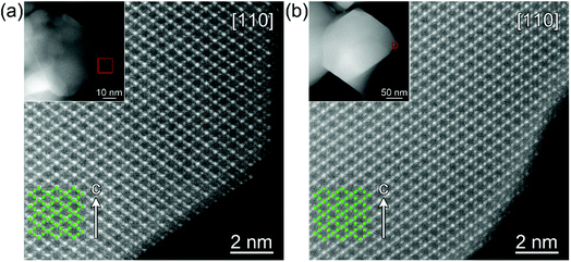
The high resolution STEM study of the surface modified LNMO samples annealed at 500 and 800 °C shows a well preserved spinel structure (Fig. 7). Rocksalt-like structure formation, reported by Wang et al.,23 was not observed on the surface; probably due to our choice of O2 as the atmosphere during anneals. There was also no separate amorphous or crystalline titania layer at the surface of LNMO after annealing.
The particle size of surface-modified LNMO-500 °C remains similar to that for bare LNMO. It can be concluded that the Ti-modified surface layer was kept intact. However, at higher temperatures the particle growth was significant. The particles of surface modified LNMO annealed at 800 °C and 850 °C are ∼1.5–5 times larger than bare LNMO annealed at the same conditions (Fig. 8). It can be suggested that apart from sintering of the particles, an additional process occurs, which is the formation of a Ti bulk doped LNMO phase. Some particles still preserve a 1–2 nm Ti-rich surface layer (Fig. 4(h and l)); while others do not, probably due to their excessive growth during high temperature anneals.
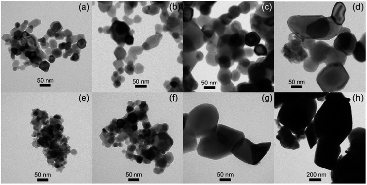 | ||
| Fig. 8 TEM images of bare LNMO after annealing at (a) 500, (b) 700, (c) 800, (d) 850 °C, and of Ti surface modified LNMO annealed at (e) 500, (f) 700, (g) 800, (h) 850 °C. | ||
The high Ti content in the surface layer and negligible in the core, the visibility of the spinel structured surface in the HR-STEM images and the absence of a significant lattice parameter increase compared to bare LNMO, all suggest that Ti doping takes place at the 2–4 nm surface without disturbing the spinel structure at 500 °C; rather than formation of a separate, amorphous or crystalline titania layer on the LNMO surface.
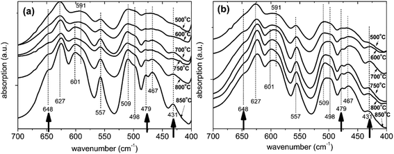 | ||
| Fig. 9 Infrared spectra of (a) bare and (b) surface modified LNMO samples prepared using 3 g LNMO, 6 mL TBOT and 0.5 mL NH3 followed by annealing in O2 at various temperatures. | ||
| Peak number | Disordered LNMO (F-type) | Ordered LNMO (P-type) | ||
|---|---|---|---|---|
| Peak position (cm−1) | Peak assignment12,48 | Peak position (cm−1) | Peak assignment12,48 | |
| a Shoulder peaks are indicated in parenthesis. | ||||
| 1 | 627 | Mn–O A1g | 648 | — |
| 2 | 591 (601) | Ni–O F2g | 627 | Mn–O A1g |
| 3 | 557 | Mn–O A1g | 591 (601) | Ni–O F2g |
| 4 | 498 (509) | Ni–O F2g | 557 | Mn–O A1g |
| 5 | 467 | — | 498 (509) | Ni–O F2g |
| 6 | — | — | 479 | — |
| 7 | — | — | 467 | — |
| 8 | — | — | 431 | — |
The number of recognizable peaks increases to eight at higher annealing temperatures. The three additional peaks are located at 648, 479 and 431 cm−1; as shown with arrows in Fig. 9. This implies more pronounced ordering for bare LNMO by applying higher annealing temperatures in an oxygen atmosphere. The annealing atmosphere has an important effect on ordering as well.16 This is further elaborated by Kunduraci et al.,12 who reported increased disordering at 800 °C when using dry air for the anneal; while increased ordering was obtained when oxygen was used for the study at hand. Our bare LNMO annealed between 600 and 850 °C is identified as a mixture of F and P-types (partial ordering), since pure P-type LNMO (long range ordering) is known to have a more intense 591 cm−1 peak compared to the 627 cm−1 peak.12,48
Fig. 9(b) shows the infrared spectra for the surface modified LNMO samples. The sample annealed at 500 °C is identified as being F-type, similar to the bare LNMO. Spectra for higher annealing temperatures are also similar to the bare ones, showing partial ordering. The 625, 557 and 467 cm−1 bands for bare LNMO with 850 °C anneal has shifted to 624, 556 and 465 cm−1, respectively, for the surface modified LNMO with 850 °C anneal (Fig. 9). This can be attributed to the presence of small amounts of Ti–O bonds with a similar vibrational wavenumber.49,53
Electrochemical performance
 | ||
| Fig. 10 20th cycle galvanostatic charge–discharge curves of half-cells made using bare and surface modified LNMO, annealed at (a) 500, (b) 700 and (c) 800 °C, measured at 0.5 C. | ||
Surface modified LNMO samples, annealed at 500 or 700 °C, show lower discharge capacities, compared to the bare ones for the first few cycles (see Table 4, Fig. 10). This is consistent with earlier reports on LNMO surface/bulk modifications with Ti cation.23,26,29,45 The Li+ migration is not hindered by Ti doping as long as the spinel structure is maintained.29 However, the electronic migration pathways could be blocked by increasing Ti concentrations for LiNi0.5Mn1.5−xTixO4; as proposed by Kim et al.29 Therefore, increased Ti concentrations in the LNMO might be a possible explanation for the reduced capacities, as the HR-STEM images indicate that the spinel structure is maintained.
| Sample | Discharge capacity (mA h g−1) | % capacity stored at 4 V region | ||
|---|---|---|---|---|
| Total capacity | 4 V regiona | 4.7 V regionb | ||
| a Includes from 3.4 to 4.4 V.b Includes from 4.4 to 4.9 V. | ||||
| Bare LNMO, 500 °C | 88.5 | 13.6 | 74.9 | 15.4 |
| Bare LNMO, 700 °C | 85.6 | 11.3 | 74.4 | 13.2 |
| Bare LNMO, 800 °C | 76.6 | 9.0 | 67.6 | 11.7 |
| Surface modified LNMO, 500 °C | 85.7 | 14.7 | 71.0 | 17.2 |
| Surface modified LNMO, 700 °C | 80.9 | 13.8 | 67.1 | 17.1 |
| Surface modified LNMO, 800 °C | 79.5 | 13.3 | 66.2 | 16.7 |
Fig. 10 shows that the capacity in LNMO is stored at two different potential regions: one centered around 4.0 V and the other centered around 4.7 V vs. Li/Li+. Mn3+ to Mn4+ oxidation takes place during charging at the 4 V region.60 However, most of the capacity is stored in the 4.7 V region, where Ni2+/4+ oxidation reaction takes place. Table 4 shows the discharge capacities for the 4.0 and 4.7 V regions for bare and surface modified samples. The capacity stored in the 4 V region decreases with annealing temperature for bare samples, due to an increase in ordering (see also Fig. 9). Surface modification of LNMO on the other hand, slightly increases the capacity stored at the 4 V region, especially when annealed at 800 °C (see Table 4). This suggests a slightly higher Mn3+ concentration together with more disordering, which is consistent with results reported by Wang et al.23
The two peaks, present in Fig. 11(a) at 4.75 and 4.78 V during charging of bare LNMO, annealed at 500 °C represent the onsets of Ni2+ to Ni3+ and Ni3+ to Ni4+ oxidation reactions, respectively.13,29 The separation between these two peaks decreases with increasing annealing temperatures, and when annealed at 800 °C the two peaks overlap as one broad peak at a higher potential, as seen in Fig. 11(b) and (c). This is probably an indication of increased cation ordering at higher annealing temperatures.61 The increase in redox potential for the ordered variant of LNMO is related to the higher energy required during Li+ intercalation/deintercalation.13,61 Fig. 11(a) shows another peak at about 4.72 V, during charging of the samples annealed at 500 °C. While it is a shoulder peak for the surface modified sample, it is a much more pronounced, well resolved peak in case of bare LNMO. Cho et al. observed a similar peak above 4.6 V for LNMO samples with a nanowire morphology.59 The peak was attributed to an increased electrolyte decomposition taking place at the cathode surface, due to the high surface area of the nanowires. This corresponds to our LNMO particles, annealed at 500 °C; being significantly smaller than those annealed at higher temperatures such as 700 or 800 °C. The suppression of this peak, which we observe for the surface modified sample in Fig. 11(a), is seen as an indication of a reduced amount of side reactions with Ti modification of the LNMO surface.
 | ||
| Fig. 12 Changes in discharge capacities with increasing cycle numbers for bare and surface modified LNMO samples measured at 0.5 C rate. Samples were annealed at (a) 500, (b) 700 and (c) 800 °C. | ||
Coulombic efficiency plots (CE% = (Qdischarge/Qcharge) × 100%) are shown in Fig. 13. Low CE% values are observed during the first few cycles of bare LNMO due to SEI and CEI formation on the anode and cathode surfaces, respectively, causing irreversible Li+ loss. Efficiencies increase after the formation of these layers. Surface modification improves the CE%, especially for the sample annealed at 500 °C, since this sample has the most disordered structure and the highest amount of Mn3+, based on the capacity curves, which results in low CE% and low cycle life, when the surface is not protected. Similar improvements in CE% were reported in literature for surface modified LNMO, especially within the first few cycles. These improvements were attributed to prevention of side reactions and Mn dissolution, causing capacity loss.22,26
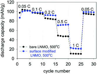
Fig. 14 shows rate performance measurements for the bare and surface modified LNMO samples, annealed at 500 °C. The capacity recovery after the final cycle, at 0.1 C, is an indication of preservation of the crystal structure. The surface-modified sample shows a better rate performance than the bare sample. Deng et al.26 similarly showed an improved rate performance for Li2TiO3 coated LNMO. However, Hao et al.22 reported rate performance drops when coating micron sized LNMO with Li4Ti5O12 (LTO). They attributed the lower rate performance to a decrease in electrical conductivity because of the presence of the LTO shell around the particles. Improved rate performances obtained in our case is probably due to preservation of the highly conductive spinel surface structure after Ti surface doping (see Fig. 7), rather than synthesis of a separate titania layer with a different crystal structure.28 Small amounts of Ti doping at the surface are useful in preventing crystal structure changes, while also maintaining a high Li+ diffusion coefficient during cycling.28,29,62
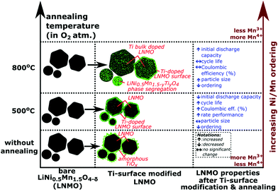
Fig. 15 shows a summary of different annealing temperatures used and their effect on the Ti positions, particle sizes and the electrochemistry. A 2–4 nm thick, Ti-rich, spinel solid solution surface forms on LNMO particle by Ti surface doping and 500 °C anneal. Higher annealing temperatures (i.e. 800, 850 °C) cause bulk doping of LNMO by Ti (i.e. LiNi(0.5−w)Mn(1.5+w)−tTitO4 phase), since the Ti on the surface diffuses towards the core. Three different particle types are observed within the 800 °C annealed sample as shown in Fig. 15: Ti bulk doped LNMO particles that still preserve a 1–2 nm, Ti-rich surface layer; Ti bulk doped LNMO particles without a Ti rich surface layer (or with discontinuities) and Ti-rich segregates (i.e. LiNi0.5Mn1.5−yTiyO4) formed by excessive Ti incorporation into some particles. Cyclic stability, CE% and rate performance is better for the surface modified LNMO than for the bare LNMO with 500 °C anneal, since the Ti-modified surface layer remains intact during annealing. On the other hand, increased Ti diffusion towards the core and particle size growth taking place during 800 °C anneal damages or reduces the thickness of the protective Ti-rich surface layer. Therefore, no significant improvement in cyclic stability or CE% was observed for the surface modified LNMO sample with 800 °C anneal, compared to the bare, 800 °C annealed LNMO.
Conclusions
By means of a hydrolysis-condensation approach, followed by 500 °C anneal, the surface of a disordered LiNi0.5Mn1.5O4−δ was modified by Ti cation doping over 2–4 nm depth, while maintaining the initial spinel structure. Particle size and surface area of the bare and surface modified LNMO remained similar after 500 °C anneal and the Ti doped surface remained intact. Although the initial discharge capacity was slightly reduced, cycle life, coulombic efficiency and rate performance were improved for Ti surface doped LNMO annealed at 500 °C compared to bare LNMO also annealed at 500 °C. The improvement is probably due to surface structure stabilization by the stronger Ti–O bonds, which reduces the manganese dissolution. On the other hand, during an 800 °C anneal, Ti diffused from the surface towards the core of LNMO, causing the formation of Ti bulk doped LiNi(0.5−w)Mn(1.5+w)−tTitO4 phase and Ti-rich LiNi0.5Mn1.5−yTiyO4 secondary phase which was accompanied by intensive particle size growth. Mn–Ni ordering in the lattice increased with 800 °C annealing in oxygen for both bare and surface modified LNMO samples, compared to 500 °C annealed samples in oxygen. However, no significant improvement was observed in cycle life or coulombic efficiency of Ti surface modified LNMO annealed at 800 °C compared to bare LNMO also annealed at 800 °C. This is probably because the Ti doped surface layer of LNMO was in this case not well preserved during Ti diffusion and particle size growth. The Ti surface-doped LNMO annealed at 500 °C, having a well preserved spinel surface structure and a disordered Mn–Ni distribution, could be an interesting candidate as a cathode material for lithium ion battery applications requiring both good cycle life and rate performance.Conflicts of interest
There are no conflicts of interest to declare.Acknowledgements
This research is supported by the Research Foundation Flanders (FWO Vlaanderen, grant number G040116N). This project receives the support of the European Union, the European Regional Development Fund ERDF, Flanders Innovation & Entrepreneurship and the Province of Limburg (project 936). Greet Cuyvers and Gilles Bonneux (UHasselt) are acknowledged for the ICP-AES sample preparation and measurements. Vera Meynen and Karen Leyssens (Antwerp University, Belgium) are acknowledged for the BET measurements. Special thanks to Bart Ruttens (UHasselt) for XRD measurements and discussions on the refinements.References
- N. Nitta, et al., Li-ion battery materials: present and future, Mater. Today, 2015, 18(5), 252–264 CrossRef CAS.
- C. M. Julien, A. Mauger, K. Zaghib and H. Groult, Comparative Issues of Cathode Materials for Li-Ion Batteries, Inorganics, 2014, 2, 132–154 CrossRef CAS.
- S. T. Myung, et al., Progress in High-Capacity Core-Shell Cathode Materials for Rechargeable Lithium Batteries, J. Phys. Chem. Lett., 2014, 5(4), 671–679 CrossRef CAS PubMed.
- B. Scrosati and J. Garche, Lithium batteries: Status, prospects and future, J. Power Sources, 2010, 195(9), 2419–2430 CrossRef CAS.
- J. B. Goodenough and K. S. Park, The Li-ion rechargeable battery: a perspective, J. Am. Chem. Soc., 2013, 135(4), 1167–1176 CrossRef CAS PubMed.
- L. Su, Y. Jing and Z. Zhou, Li ion battery materials with core-shell nanostructures, Nanoscale, 2011, 3(10), 3967–3983 RSC.
- C. Y. Ouyang, S. Q. Shi and M. S. Lei, Jahn–Teller distortion and electronic structure of LiMn2O4, J. Alloys Compd., 2009, 474(1–2), 370–374 CrossRef CAS.
- D.-Q. Liu, X.-Q. Liu and Z.-Z. He, The elevated temperature performance of LiMn2O4 coated with Li4Ti5O12 for lithium ion battery, Mater. Chem. Phys., 2007, 105(2–3), 362–366 CAS.
- Q. Zhong, A. Bonakdarpour, M. Zhang, Y. Gao and J. R. Dahn, Synthesis and electrochemistry of LiNixMn2−xO4, J. Electrochem. Soc., 1997, 144(1), 205 CrossRef CAS.
- R. Santhanam and B. Rambabu, Research progress in high voltage spinel LiNi0.5Mn1.5O4 material, J. Power Sources, 2010, 195(17), 5442–5451 CrossRef CAS.
- C. M. Julien and A. Mauger, Review of 5-V electrodes for Li-ion batteries: status and trends, Ionics, 2013, 19(7), 951–988 CrossRef CAS.
- M. Kunduraci and G. G. Amatucci, Synthesis and Characterization of Nanostructured 4.7 V LixMn1.5Ni0.5O4 Spinels for High-Power Lithium-Ion Batteries, J. Electrochem. Soc., 2006, 153(7), A1345 CrossRef CAS.
- H. Duncan, et al., Relationships between Mn3+ Content, Structural Ordering, Phase Transformation, and Kinetic Properties in LiNixMn2−xO4 Cathode Materials, Chem. Mater., 2014, 26(18), 5374–5382 CrossRef CAS.
- M. Kunduraci and G. G. Amatucci, Effect of oxygen non-stoichiometry and temperature on cation ordering in LiMn2−xNixO4 (0.50 ≥ x ≥ 0.36) spinels, J. Power Sources, 2007, 165(1), 359–367 CrossRef CAS.
- Guoqiang, L., LiNi0.5Mn1.5O4 Spinel and Its Derivatives as Cathodes for LIBs, in http://www.intechopen.com.
- G. Liu, et al., Influence of thermal history on the electrochemical properties of Li[Ni0.5Mn1.5]O4, J. Power Sources, 2013, 243, 260–266 CrossRef CAS.
- N. V. Kosova, et al., Peculiarities of structure, morphology, and electrochemistry of the doped 5-V spinel cathode materials LiNi0.5−xMn1.5−yMx+yO4 (M
![[thin space (1/6-em)]](https://www.rsc.org/images/entities/char_2009.gif) =
= ![[thin space (1/6-em)]](https://www.rsc.org/images/entities/char_2009.gif) Co, Cr, Ti; x + y
Co, Cr, Ti; x + y ![[thin space (1/6-em)]](https://www.rsc.org/images/entities/char_2009.gif) =
= ![[thin space (1/6-em)]](https://www.rsc.org/images/entities/char_2009.gif) 0.05) prepared by mechanochemical way, J. Solid State Electrochem., 2015, 20(1), 235–246 CrossRef.
0.05) prepared by mechanochemical way, J. Solid State Electrochem., 2015, 20(1), 235–246 CrossRef. - J. Vetter, et al., Ageing mechanisms in lithium-ion batteries, J. Power Sources, 2005, 147(1–2), 269–281 CrossRef CAS.
- J.-K. Park, Principles and Applications of Lithium Secondary Batteries, 2012 Search PubMed.
- J.-H. Kim and N. P. W. Pieczonka, et al., Understanding Transition-Metal Dissolution Behavior in LiNi0.5Mn1.5O4 High-Voltage Spinel for Lithium Ion Batteries, J. Phys. Chem. C, 2013, 117(31), 15947–15957 Search PubMed.
- J. Ma, et al., Surface and Interface Issues in Spinel LiNi0.5Mn1.5O4: Insights into a Potential Cathode Material for High Energy Density Lithium Ion Batteries, Chem. Mater., 2016, 28(11), 3578–3606 CrossRef CAS.
- X. Hao and B. M. Bartlett, Improving the Electrochemical Stability of the High-Voltage Li-Ion Battery Cathode LiNi0.5Mn1.5O4 by Titanate-Based Surface Modification, J. Electrochem. Soc., 2013, 160(5), A3162–A3170 CrossRef CAS.
- H. Wang, et al., Understanding the effects of surface reconstruction on the electrochemical cycling performance of the spinel LiNi0.5Mn1.5O4 cathode material at elevated temperatures, J. Mater. Chem. A, 2017, 5(2), 822–834 CAS.
- L. Yang, B. Ravdel and B. L. Lucht, Electrolyte Reactions with the Surface of High Voltage LiNi0.5Mn1.5O4 Cathodes for Lithium-Ion Batteries, Electrochem. Solid-State Lett., 2010, 13(8), A95 CrossRef CAS.
- Y.-R. Zhu, T.-F. Yi, R.-S. Zhu and A.-N. Zhou, Increased cycling stability of Li4Ti5O12-coated LiMn1.5Ni0.5O as cathode material for lithium-ion batteries, Ceram. Int., 2013, 39, 3087–3094 CrossRef CAS.
- H. Deng, P. Nie, H. Luo, Y. Zhang, J. Wang and X. Zhang, Highly enhanced lithium storage capability of LiNi0.5Mn1.5O4 by coating with Li2TiO3 for Li-ion batteries, J. Mater. Chem. A, 2014, 2(43), 18256–18262 CAS.
- J. Li, Y. Zhu, L. Wang and C. Cao, Lithium titanate epitaxial coating on spinel lithium manganese oxide surface for improving the performance of lithium storage capability, ACS Appl. Mater. Interfaces, 2014, 6(21), 18742–18750 CAS.
- J. Lu, et al., Effectively suppressing dissolution of manganese from spinel lithium manganate via a nanoscale surface-doping approach, Nat. Commun., 2014, 5, 5693 CrossRef CAS PubMed.
- J. H. Kim, et al., Effect of Ti Substitution for Mn on the Structure of LiNi0.5Mn1.5−xTixO4 and Their Electrochemical Properties as Lithium Insertion Material, J. Electrochem. Soc., 2004, 151(11), A1911 CrossRef CAS.
- D. Liu and Z. M. Yates, Fabrication of size-tunable TiO2 tubes using rod-shaped calcite templates, Langmuir, 2007, 23, 10333–10341 CrossRef CAS PubMed.
- W. Li, et al., A versatile kinetics-controlled coating method to construct uniform porous TiO2 shells for multifunctional core–shell structures, J. Am. Chem. Soc., 2012, 134(29), 11864–11867 CrossRef CAS PubMed.
- Malvern Instruments, Chapter 16: Zeta potential theory, Zetasizer nano series user manual, 2004 Search PubMed.
- ASTM, Standard Test Method for Determination of pHe of Ethanol, Denatured Fuel Ethanol, and Fuel Ethanol in D 6423 – 99, 1999.
- C. A. Schneider, W. S. Rasband and K. W. Eliceiri, NIH Image to ImageJ: 25 years of image analysis, Nat. Methods, 2012, 9(7), 671–675 CrossRef CAS PubMed.
- A. C. Larson and R. B. Von Dreele, General Structure Analysis System (GSAS), Los Alamos National Laboratory Report LAUR 86-748, 2000 Search PubMed.
- B. H. Toby, EXPGUI, a graphical user interface for GSAS, J. Appl. Crystallogr., 2001, 34, 210–213 CrossRef CAS.
- J. Livage, M. Henry and C. Sanchez, Sol–gel chemistry of transition metal oxides, Prog. Solid State Chem., 1988, 18, 259 CrossRef CAS.
- J. Widegren and L. Bergström, The effect of acids and bases on the dispersion and stabilization of ceramic particles in ethanol, J. Eur. Ceram. Soc., 2000, 20, 659–665 Search PubMed.
- P. Wang, D. Chen and F.-Q. Tang, Preparation of titania-coated polystyrene particles in mixed solvents by ammonia catalysis, Langmuir, 2006, 22, 4832 CrossRef CAS PubMed.
- K. R. Chemelewski, et al., Factors Influencing the Electrochemical Properties of High-Voltage Spinel Cathodes: Relative Impact of Morphology and Cation Ordering, Chem. Mater., 2013, 25(14), 2890–2897 CrossRef CAS.
- L. Ying, L. S. Hon, T. White, R. Withers and L. B. Hai, Controlled Nanophase Development in Photocatalytic Titania, Mater. Trans., 2003, 44(7), 1328 CrossRef CAS.
- J. Xiao, et al., High-performance LiNi0.5Mn1.5O4 spinel controlled by Mn3+ concentration and site disorder, Adv. Mater., 2012, 24(16), 2109–2116 CrossRef CAS PubMed.
- M.-L.-P. Le, et al., Spinel-type solid solutions involving Mn4+ and Ti4+: crystal chemistry, magnetic and electrochemical properties, J. Phys. Chem. Solids, 2011, 72(2), 124–135 CrossRef CAS.
- R. Alcantara, M. Jaraba, P. Lavela and J. L. Tirado, Structural and Electrochemical Study of New LiNi0.5TixMn1.5−xO4 Spinel Oxides for 5-V Cathode Materials, Chem. Mater., 2003, 15, 2376–2382 CrossRef CAS.
- M. Lin, et al., A Strategy to Improve Cyclic Performance of LiNi0.5Mn1.5O4 in a Wide Voltage Region by Ti-Doping, J. Electrochem. Soc., 2013, 160(5), A3036–A3040 CrossRef CAS.
- J.-H. Kim, et al., Improved lithium-ion battery performance of LiNi0.5Mn1.5−xTixO4 high voltage spinel in full-cells paired with graphite and Li4Ti5O12 negative electrodes, J. Power Sources, 2014, 262, 62–71 CrossRef CAS.
- W. Branford, M. A. Green and D. A. Neumann, Structure and ferromagnetism in Mn4+ spinels: AM0.5Mn1.5O4 (A = Li, Cu; M = Ni, Mg), Chem. Mater., 2002, 14, 1649–1656 CrossRef CAS.
- K. Ariyoshi, et al., Topotactic Two-Phase Reactions of Li[Ni1/2Mn3/2]O4 P4332 in Nonaqueous Lithium Cells, J. Electrochem. Soc., 2004, 151(2), A296 CrossRef CAS.
- J. Deng, et al., Improving the fast discharge performance of high-voltage LiNi0.5Mn1.5O4 spinel by Cu2+, Al3+, Ti4+ tri-doping, J. Alloys Compd., 2016, 677, 18–26 CrossRef CAS.
- J.-H. Kim, et al., Understanding the capacity fading mechanism in LiNi0.5Mn1.5O4/graphite Li-ion batteries, Electrochim. Acta, 2013, 90, 556–562 CrossRef CAS.
- P. Strobel, et al., Cation ordering in Li2Mn3MO8 spinels: structural and vibration spectroscopy studies, Solid State Sci., 2003, 5(7), 1009–1018 CrossRef CAS.
- L. Wang, et al., Improved structural and electrochemical performances of LiNi0.5Mn1.5O4 cathode materials by Cr3+ and/or Ti4+ doping, RSC Adv., 2015, 5(121), 99856–99865 RSC.
- D. Gryffroy and R. E. Vandenberghe, Cation distribution, cluster structure and ionic ordering of the spinel series LiNi0.5Mn1.5−xTixO4 and LiNi0.5−yMgyMn1.5O4, J. Phys. Chem. Solids, 1992, 53(6), 777–784 CrossRef CAS.
- M. Takagi, Y. Murota, M. Tajima, T. Asao, M. Saito, A. Tasaka and M. Inaba, Improvement of electrochemical properties of a high potential negative electrode TiO2(B), ECS Trans., 2011, 33(29), 57–66 CAS.
- J. Cabana, et al., Comparison of the Performance of LiNi1/2Mn3/2O4 with Different Microstructures, J. Electrochem. Soc., 2011, 158(9), A997 CrossRef CAS.
- J. Mao, K. Dai and Y. Zhai, Electrochemical studies of spinel LiNi0.5Mn1.5O4 cathodes with different particle morphologies, Electrochim. Acta, 2012, 63, 381–390 CrossRef CAS.
- J. Yang, et al., Spinel LiNi0.5Mn1.5O4 cathode for rechargeable lithium ion batteries: Nano vs micro, ordered phase (P4332) vs disordered phase (Fd
![[3 with combining macron]](https://www.rsc.org/images/entities/char_0033_0304.gif) m), Nano Res., 2013, 6(9), 679–687 CrossRef CAS.
m), Nano Res., 2013, 6(9), 679–687 CrossRef CAS. - J. C. Arrebola, et al., Expanding the Rate Capabilities of the LiNi0.5Mn1.5O4 Spinel by Exploiting the Synergistic Effect Between Nano and Microparticles, Electrochem. Solid-State Lett., 2005, 8(12), A641 CrossRef CAS.
- H.-M. Cho, et al., Effect of Surface Modification on Nano-Structured LiNi0.5Mn1.5O4 Spinel Materials, ACS Appl. Mater. Interfaces, 2015, 7(30), 16231–16239 CAS.
- Y. Terada, et al., In Situ XAFS Analysis of Li(Mn, M)2O4 (M = Cr, Co, Ni) 5 V Cathode Materials for Lithium-Ion Secondary Batteries, J. Solid State Chem., 2001, 156(2), 286–291 CrossRef CAS.
- J.-H. Kim, S.-T. Myung, C. S. Yoon, S. G. Kang and Y.-K. Sun, Comparative study of LiNi0.5Mn1.5O4−δ and LiNi0.5Mn1.5O4 Cathodes Having Two Crystallographic Structures: Fd3m and P4332, Chem. Mater., 2004, 16, 906–914 CrossRef CAS.
- J.-M. Lim, et al., Design of Surface Doping for Mitigating Transition Metal Dissolution in LiNi0.5Mn1.5O4 Nanoparticles, ChemSusChem, 2016, 9(20), 2967–2973 CrossRef CAS PubMed.
Footnote |
| † Electronic supplementary information (ESI) available. See DOI: 10.1039/c7ra12932g |
| This journal is © The Royal Society of Chemistry 2018 |


