
 Open Access Article
 This Open Access Article is licensed under a Creative Commons Attribution-Non Commercial 3.0 Unported Licence
Large magnetic entropy change and prediction of magnetoresistance using a magnetic field in La0.5Sm0.1Sr0.4Mn0.975In0.025O3
M. Dhahri *a,
J. Dhahria and
E. K. Hlilb
*a,
J. Dhahria and
E. K. Hlilb
aLaboratoire de la matière condensée et des nanosciences, Univercité de Monastir, 5019, Tunisia. E-mail: mmay988205@gmail.com
bInstitut Neel, CNRS et Univercité Joseph Fourrier, B. P. 166, 38042 Grenoble, France
First published on 31st January 2018
Abstract
A detailed study of the structural, magnetic, magnetocaloric and electrical effect properties in polycrystalline manganite La0.5Sm0.1Sr0.4Mn0.975In0.025O3 is presented. The X-ray diffraction pattern is consistent with a rhombohedral structure with R![[3 with combining macron]](https://www.rsc.org/images/entities/char_0033_0304.gif) c space group. Experimental results revealed that our compound prepared via a sol–gel method exhibits a continuous (second-order) ferromagnetic (FM) to paramagnetic (PM) phase transition around the Curie temperature (TC = 300 K). In addition, the magnetic entropy change was found to reach 5.25 J kg−1 K−1 under an applied magnetic field of 5 T, corresponding to a relative cooling power (RCP) of 236 J kg−1. We have fitted the experimental data of resistivity using a typical numerical method (Gauss function). The simulation values such as maximum resistivity (ρmax) and metal–semiconductor transition temperature (TM–Sc), calculated from this function, showed a perfect agreement with the experimental data. The shifts of these parameters as a function of magnetic field for our sample have been interpreted. The obtained values of β and γ, determined by analyzing the Arrott plots, are found to be TC = 298.66 ± 0.64 K, β = 0.325 ± 0.001 and γ = 1.25 ± 0.01. The critical isotherm M (TC, μ0H) gives δ = 4.81 ± 0.01. These critical exponent values are found to be consistent and comparable to those predicted by the three-dimensional Ising model with short-range interaction. Thus, the Widom scaling law
c space group. Experimental results revealed that our compound prepared via a sol–gel method exhibits a continuous (second-order) ferromagnetic (FM) to paramagnetic (PM) phase transition around the Curie temperature (TC = 300 K). In addition, the magnetic entropy change was found to reach 5.25 J kg−1 K−1 under an applied magnetic field of 5 T, corresponding to a relative cooling power (RCP) of 236 J kg−1. We have fitted the experimental data of resistivity using a typical numerical method (Gauss function). The simulation values such as maximum resistivity (ρmax) and metal–semiconductor transition temperature (TM–Sc), calculated from this function, showed a perfect agreement with the experimental data. The shifts of these parameters as a function of magnetic field for our sample have been interpreted. The obtained values of β and γ, determined by analyzing the Arrott plots, are found to be TC = 298.66 ± 0.64 K, β = 0.325 ± 0.001 and γ = 1.25 ± 0.01. The critical isotherm M (TC, μ0H) gives δ = 4.81 ± 0.01. These critical exponent values are found to be consistent and comparable to those predicted by the three-dimensional Ising model with short-range interaction. Thus, the Widom scaling law  is fulfilled.
1. Introduction
Over the past few years, magnetic refrigeration (MR) based on the magnetocaloric effect (MCE) has become a promising technology to replace the conventional gas-compression refrigeration due to its energy-efficient, environment-friendly advantages and economical benefits. It has been pointed out that suitable materials should be cost effective and possess a large MCE (large isothermal magnetic entropy change ΔSM) over a wide temperature range. Among them, perovskite manganites with generic formula Ln1−xAxMnO3 (Ln represents trivalent rare-earth elements such as La, Pr, Nd, Sm, etc., and A stands for divalent alkaline-earth cations such as Ca2+, Sr2+, Ba2+, etc.), have attracted considerable scientific and technological interest owing to their important magnetic and electrical properties,1,2 such as the notable colossal magnetoresistance (CMR) and the magnetocaloric effect (MCE) under a moderate applied field, which is characterized by magnetic entropy change (ΔSM) and relative cooling power (RCP). Furthermore, there is also a book written by Tishin and Spichkin3 which describes numerous different magnetocaloric materials in detail.Also, manganese oxides especially, the La–Sr based manganite (La0.7Sr0.3MnO3) exhibit a metal–semiconductor transition (MSc) accompanied by a FM–PM transition near TC. In a recent publication4,5 there have been few models that can explain the transport mechanism in manganites. Among them, we point out the small polaron hopping (SPH) model and the 3D Mott's variable range hopping (VRH) in the semiconducting region, the adiabatic small polaron hopping mechanism6 and electron–electron, electron–phonon processes in the metallic region. These laws are very important in manganite research because they very well describe the observed high-temperature variation (T > TM–Sc) in the conduction mechanism.
However, there is still no clear conclusion of whether or not the resistivity ρ(T) can be continuously predicted by temperature from the metal phase to the semiconductor phase for individual manganite with only one equation.
Unfortunately, few studies have been done on the mathematical model which can describe the carrier transport behavior of manganite as a function of temperature around the metal semiconducting transition and the relation between magnetic and electrical properties. In this contribution, we have determined the correlation between electrical and magnetic properties and we have developed a mathematical model to quantitatively analyze the temperature-dependent resistivity.
Many previous reports were dedicated that the most accepted interpretations for the origin of these properties are the double exchange model and Jahn–Teller effect7 which they are used to identify the magnetic phase transitions (FM–PM).
Therefore, to understand better the relation between CMR effect and the semiconductor–metal transition, two important questions about FM–PM transition should be clarified: one is the order of phase transition; the other is the common universality class. A most useful approach is the consideration of the critical exponents. These describing the thermodynamic properties near the phase transition can be used to elucidate interactions mechanisms near TC. In earlier theoretical works,8,9 the critical behavior related to the FM–PM transition in manganites within the DE model was first described with long-range mean-field theory. Later, depending on the computational technology for the CMR of manganites, Motome and Furukawa suggested that the FM–PM transition should belong to Heisenberg's universality Class.10,11 However, some research have predicted that the critical exponents in manganites are in agreement with a short range exchange interaction model with the estimated critical exponent values related to either 3D-Heisenberg or 3D-Ising model.
Critical exponents for manganites show wide variation that almost covers all universality classes and different experimental tools are used for their determination. Ghosh et al.12 reported that the calculated values of the critical exponent β is equal to 0.37 for the manganite La0.7Sr0.3MnO3. However, La0.8Sr0.2MnO3 is in good agreement with that in mean-field model13 with a relative high value of β (=0.5). While a very low critical exponent of β = 0.14 identified in the single crystal La0.7Ca0.3MnO3 suggested that the FM–PM transition in this system is of a first rather than second order type.14 With this variety in mind, it is worthwhile to study the critical behavior in the same perovskite manganite.
The present work aims basically at investigating the structural, magnetic, magnetocaloric, electrical and the critical behavior for La0.5Sm0.1Sr0.4Mn0.975In0.025O3 (LSSMIO) manganite. We used four kinds of different theoretical models, which are mean field, 3D-Heisenberg, 3D-Ising, and tricritical mean field to explain the critical behavior in the manganite.
2. Experimental details
LSSMIO compound was fabricated using a conventional sol–gel method, it is known to produce very high quality, homogeneous and fine particle materials.In this method, the stoichiometric amounts of high purity nitrate Sr(NO3)2·6H2O; La(NO3)3·6H2O; Mn(NO3)2·4H2O; Sm(NO3)3·6H2O and In(NO3)3·xH2O precursors were taken as starting materials in appropriate stoichiometric ratio powder and pH was adjusted between 6.5 and 7. In the first step, the precursor solution was prepared by dissolving the constituents (precursors/starting materials) with desired composition in deionized water. In the next step, the homogeneous precursor solution was heated to 90 °C under constant stirring to eliminate the excess water and get a dry fluffy porous mass. Subsequently, the obtained sol was cooled before the addition of ethylene glycol (EG) (1![[thin space (1/6-em)]](https://www.rsc.org/images/entities/char_2009.gif) :1; EG:CA) and citric acid (CA) (CA:metal ion molar ratios of 1, 2 or 3) which they were used as polymerization/complexation (PC) agents. The process was heated first at 340–380 K with a vigorous stirring to evaporate water, accelerate the poly-esterification reaction between CA and EG and increase viscosity. Then the temperature was raised up to 450 K forming a dark viscous gel which slowly turned into a dark resin. This resin was easily powdered in an agate mortar and was calcined at 600 K for 7 h in oxygen atmosphere to eliminate the other organic compounds the carbons gases and give a fine powder. Finally, the resulting powder was uniaxial pressed at 105 Pa into pellets with a thickness of 2 mm and diameter of 8 mm. The obtained black pellets were sintered in air at 900 °C for 15 h.
:1; EG:CA) and citric acid (CA) (CA:metal ion molar ratios of 1, 2 or 3) which they were used as polymerization/complexation (PC) agents. The process was heated first at 340–380 K with a vigorous stirring to evaporate water, accelerate the poly-esterification reaction between CA and EG and increase viscosity. Then the temperature was raised up to 450 K forming a dark viscous gel which slowly turned into a dark resin. This resin was easily powdered in an agate mortar and was calcined at 600 K for 7 h in oxygen atmosphere to eliminate the other organic compounds the carbons gases and give a fine powder. Finally, the resulting powder was uniaxial pressed at 105 Pa into pellets with a thickness of 2 mm and diameter of 8 mm. The obtained black pellets were sintered in air at 900 °C for 15 h.
Indeed, the microstructure was observed by a scanning electron microscope (SEM) using a Philips XL30 and semi-quantitative analysis was performed at a 20 kV accelerating voltage using energy dispersive X-ray analyses (EDAX). To extract the critical exponent of the sample accurately, the magnetic measurements were performed in the range of 0–5T, near the FM to PM phase transition using a BS1 and BS2 magnetometer developed in Louis Neel Laboratory, Grenoble. In fact, the isothermals are corrected by a demagnetization factor Da that has been determined by a standard procedure from the low-field linear-response regime at a low temperature (μ0Happl − DaM).
3. Results and discussion
3.1. Structural and morphological study
XRD patterns at room temperature (Fig. 1) confirmed that our sample have no trace of any impurity phase. The Bragg reflections indicate that our manganite crystallizes in a single phase with rhombohedral structure (space group Rc). The structural parameters are refined by a standard Rietveld technique.15 The refined XRD pattern for our sample is shown in Fig. 1 and the resulting lattice parameter as well as the corresponding agreement factors are tabulated in Table 1. The substitution of In3+ for Mn3+ causes a distortion of cell, an elongation along the a and c axes, and as a result an increase of the cell volume.
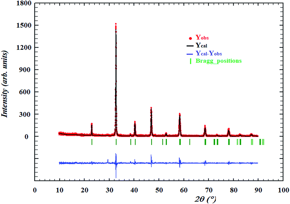 | ||
| Fig. 1 Rietveld refinement for the sample LSSMIO. Experimental data (the point symbols), calculated data (the solid lines), difference between them is shown at the bottom of the diagram and Bragg positions are marked by vertical bars. | ||
| Parameters | La0.5Sm0.1Sr0.4Mn0.975In0.025O3 |
| Structure type | Rhombohedral |
| Space group | Rc |
|
|
| Lattice parameter | |
| a (Å) | 5.478(2) |
| c (Å) | 13.379(5) |
| Vunit cell (Å3) | 347.69 |
| (O)Biso (Å2) | 1.530 |
| (O)x | 0.4460(5) |
| (La, Sm, Sr)Biso (Å2) | 0.786(3) |
| (Mn, In)Biso (Å2) | 0.543(4) |
|
|
| Discrepancy factors (%) | |
| Bragg R-factor | 2.14 |
| Rp | 6.7 |
| Rwp | 9.1 |
| RF-factor | 5.8 |
| Goodness of fit χ2 | 1.68 |
The average crystallite size values have been estimated from the full width at half maximum of X-ray diffraction peaks and calculated using Scherer's equation given as:16
 | (1) |
| βSch = βobs2 − βinstr2 | (2) |
|
(β2)instr = Utan(θ)2 + Vtan(θ) + W
| (3) |
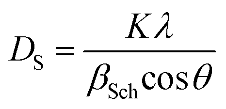
The DS value is found to be 87 nm. The SEM micrograph of our sample is shown in Fig. 2(b). Moreover, the average grain size was calculated using the average size linear intercept method from the micrograph. The value is DSEM = 210 nm. We note that the grain size obtained by SEM (DSEM) is much larger than that calculated by Scherrer's formula which can be explained by the fact that each particle observed by SEM is formed by several crystallized grains.18
 | ||
| Fig. 2 (a) EDAX spectrum for LSSMIO compound. (b) Shows the typical SEM. | ||
In order to check the existence of all elements in these compounds, energy dispersive X-ray analysis (EDAX) was carried out at room temperature. EDAX spectrum represented in Fig. 2(a) reveals the presence of La, Sm, Sr, Mn, In and O elements, which confirms that there is no loss of any integrated elements during the sintering within experimental errors. The typical cationic composition for the sample is represented in Table 2. EDAX analysis shows that the chemical composition of the sample is close to the nominal one within the experimental uncertainties.
| Chemical species | Nominal composition | ||||
|---|---|---|---|---|---|
| La | Sm | Sr | Mn | In | |
| 0.499 | 0.101 | 0.389 | 0.974 | 0.026 | La0.5Sm0.1Sr0.4Mn0.975In0.025O3 |
3.2. Magnetic and magnetocaloric study
Fig. 3 presents the temperature dependence of the magnetization measured in a constant magnetic field of 0.05T for LSSMIO sample. Apparently, our sample undergoes a phase transition from ferromagnetic (FM) to paramagnetic (PM) state at the ferromagnetic Curie temperature which is about TC = 300 K, defined as the inflection point of dM/dT (inset. a Fig. 3). The phase transition of our sample is of second order. It also behaves a large of the range of temperature. This is a typical behavior of the sample fabricated by sol–gel method. The range of the wide of transition does not seems to reflect the chemical disorder but seems due to the disorder in magnetism. It may be in a result of phase separation phenomenal.19 The experimental results showed that the doping of In3+ causes a substantial change in the magnetic properties of LSSMIO sample. Besides the ferromagnetism is due to the double exchange interaction between the Mn4+ and Mn3+ ions.20 According to Lonzarich and Taillefer,21 the manganites are ruled by spin wave theory. As for this theory magnetization varies as T3/2 (Bloch's law) at very low temperatures22 and as T2 over a wide range of temperatures, whereas close to TC, it varies as (1 − T4/3/TC4/3)1/2. In view of this, the magnetization data in the ferromagnetic region have been fitted to an equation:| M(T) = M0 + M3/2T3/2 + M2T2 | (4) |
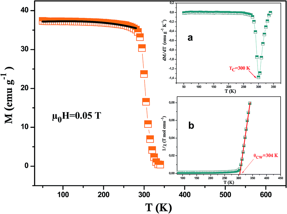 | ||
| Fig. 3 Temperature dependence of magnetization M(T) measured at 0.05T for LSSMIO sample and the solid line (black color) is the nonlinear curve fit following eqn (4). The (a) inset shows the plot of dM/dT as a function of temperature at μ0H = 0.05T and the (b)inset shows the temperature dependence of the inverse magnetic susceptibility. | ||
In order to better understand the magnetic behavior of our sample, we have fitted the inverse of the susceptibility as a function of temperature χ0−1(T) defined as (M = χH) (inset. b Fig. 3), using the following Curie–Weiss (CW) law:
 | (5) |
 | (6) |
Generally, the difference between (θCW = 304 K) value and (TC = 300 K) value depends on the substance and is associated with the presence of short-range ordered slightly above TC, which may be related to the presence of a magnetic inhomogeneity. From the determined Curie constant C, we have deduced the experimental effective moment μexpeff using the following relation:23
 | (7) |
| μeff(S) = gμB[S(S + 1)]1/2 | (8) |
Then, we have calculated the effective paramagnetic moment per formula unit which can be written as:
 | (9) |
The μexpeff and μtheoeff values are 4.85 and 4.47, respectively. The experimental value of the effective paramagnetic moment is higher than the theoretical one. It is the signature of Mn4+ and Mn3+ clusters,24 which can be explained by the presence of a short-range magnetic order in the paramagnetic phase. So that in this phase, the magnetic spins do not exist as individuals, they rather exist in small groups.
Magnetization versus magnetic field (M − μ0H) curve of LSSMIO compound at 5 K is plotted in Inset. a Fig. 4. The sample closely reach a constant value of magnetization under an applied field μ0H = 1.5T. The estimated magnetic moments from magnetization data at 5 K is 3.45μB per formula unit. A rough estimation of the expected magnetic moment can be made, based on the chemical formula La0.53+Sm0.13+Sr0.42+(Mn0.6 − x3+Mn0.44+)Inx3+O32− leading to a magnetic moment: Msp = (4 × (0.6 − x) + 3 × 0.4)μB = (3.6 − 4x)μB, as Mn3+ and Mn4+ ions have magnetic moments of 4μB and 3μB respectively. The calculated value of magnetic moment per formula unit is 3.5μB for our sample.
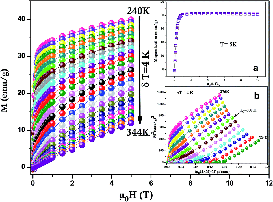 | ||
| Fig. 4 Isothermal magnetization curves of LSSMIO sample. The (a) inset shows Magnetization versus field (M − μ0H) curve at 5 K for LSSMIO sample. The (b) inset shows Standard Arrott plot (isotherms M2 vs. μ0H/M). | ||
The magnetocaloric effect MCE which is an intrinsic property of all magnetic materials, is the tendency of the material to heat up or cool down during the application or removal of a magnetic field. The applied importance of the MCE is easily appreciated from the fact that for many years it has been used successfully to reach ultra-low temperatures in a research environment.25,26 Besides, it is maximized when the material is near its magnetic ordering temperature (Curie temperature TC). In order to examine this property we have carried out the isothermal M(μ0H) measurements at different temperatures (with temperature interval δT = 4 K) in the FM–PM transition region for the sample (Fig. 4). To guarantee that magnetization data were determined in isothermal conditions, the sweep rat of the magnetic field was set slowly enough. The magnetization curve of LSSMIO manganite at temperatures below TC exhibit sharp increase of magnetization at low fields and then a gradual saturation at high fields reflecting a paramagnetic behavior.27 This magnetization is all the smaller as the temperature is high, which means that the thermal agitation is important.
In order to enquire the efficiency of our sample in the magnetic refrigeration systems, the magnetic entropy change ΔSM(T, μ0H) due to the application of a magnetic field μ0H can be calculated from a family of isothermal M–μ0H curves, using the following formula:
 | (10) |
From Maxwell relation (−ΔSM) was induced by changing the magnetic field from zero to (μ0H):
 | (11) |
 is the experimental value obtained from M(T) curves under magnetic field μ0H. One can use the following expression:
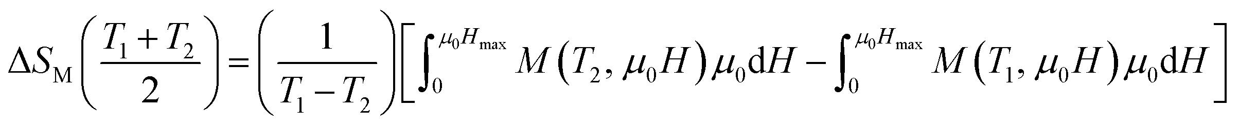 | (12) |
Using eqn (12), we have calculated the magnetic entropy change under different field changes for LSSMIO manganite as seen in Fig. 5. The change of magnetic entropy of a magnetic material has the largest value near a phase transition, where the magnetization changes rapidly with temperature.28,29
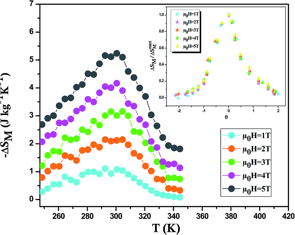 | ||
| Fig. 5 Temperature dependence of magnetic entropy change under different external fields for LSSMIO compound. The inset shows universal behavior of the scaled entropy change curves of LSSMIO sample at different fields. | ||
The peak magnitude increases with the increase in the applied magnetic field μ0H but the peak position is closely unaffected because of the second order nature of the ferromagnetic transition in this compound. It should be noted that for each magnetic applied field (−ΔSmaxM) reaches the maxima value at the Curie temperature (TC = 300 K). The values of (−ΔSmaxM), which increases with increasing the applied magnetic field, are 5.25 and 2.11 kg−1 K−1 upon a magnetic field change of 5T and 2T, respectively.
On the other hand, magnetic refrigerants are desired to have not only a large (−ΔSM) but also a large refrigerant relative cooling power (RCP). This factor corresponds to the amount of heat per kilogram that can be transferred between the cold and hot tanks during an ideal refrigeration cycle and defined as:30
| RCP = −ΔSmaxM × δTFWHM | (13) |
The RCP values as well as the maximum values of the magnetic entropy change under a magnetic applied field of 5T are summarized in Table 3. We remarque that the RCP factor undergo a moderate increase with the amplification of the magnetic field. The significant value of the RCP would confirms the transport of a greater amount of heat in an ideal refrigeration cycle. We can see that these results are interesting compared with other compounds31–38 reported in the literature (Table 3), so we can estimate that our compound is a potential candidate to be used in the magnetic refrigeration.
| Material | TC (K) | μ0H (T) | ΔSmaxM (J kg−1 K−1) | RCP (J kg−1) | Ref. |
|---|---|---|---|---|---|
| La0.5Sm0.1Sr0.4Mn0.975In0.025O3 | 300 | 5 | 5.25 | 236 | This work |
| Gd | 293 | 5 | 9.5 | 410 | 31 |
| Gd5Si2Ge2 | 275 | 5 | 18.5 | 535 | 32 |
| La0.7Sr0.3MnO3 | 370 | 5 | 5.15 | 252 | 33 |
| La0.7Ca0.3MnO3 | 264 | 5 | 7.7 | — | 34 |
| La0.7Ca0.2Sr0.1MnO3 | 308 | 5 | 7.5 | 374 | 35 |
| La0.57Y0.1Ba0.23Ca0.1MnO3 | 300 | 5 | 4.34 | 349 | 36 |
| La0.67Sr0.33Mn0.9Cr0.1O3 | 328 | 5 | 5 | — | 37 |
| La0.7Ca0.1Pb0.2Mn0.9Al0.05Sn0.05O3 | 295 | 5 | 2.3 | 135 | 38 |
| La0.7Ca0.1Pb0.2Mn0.85Al0.075Sn0.075O3 | 290 | 5 | 2 | 176 | 38 |
Franco et al.39 proposed that the phenomenological universal curve is made by normalizing all the magnetic entropy change (ΔS(T, μ0H)/ΔSmaxM). Here, ΔSmaxM presents the peak maximum of the magnetic entropy change at different magnetic fields (shown in Inset. Fig. 5) and by rescaling the temperature axis, namely (θ), below and above TC, as noted:
 | (14) |
Knowing that Tr1 and Tr2 present the temperatures of two reference points corresponding to ΔSM(Tr1,2) = 1/2ΔSmaxM. It's clear from this figure that the experimental points distribute on one universal curve. The existence of the universal curve of (−ΔSM) around TC confirms the second nature order phase transition.
3.3. Prediction of electrical resistivity
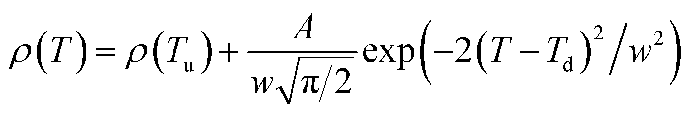
Fig. 6 shows the resistivity versus temperature behavior of LSSMIO manganite at an applied magnetic field of 0 to 5T. Our sample exhibit metal–semiconducting transition at a temperature TM–Sc which is obtained from the inflection point of dρ/dT plots. The resistivity of manganite is determined by several parameters such as the applied magnetic field, temperature, composition and so on. To understand these properties of the sample, based on the mathematical relationship between the resistivity and magnetic field or the temperature, we have to fit these curves. Shi40 reported that there are two paths for curve fitting: One way is to directly apply the fitting function; another way is to create a mathematical model when there is no appropriate fitting function available. According to this suggestion and after checking the fitting function, we can say that the Gauss function, which is a typical numerical method with a nonlinear curve fitting for the quantitative analysis, offers such an opportunity. The applicable Gauss function is expressed by:
 | (15) |
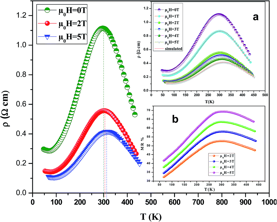 | ||
| Fig. 6 Resistivity vs. temperature curves of LSSMIO sample under different applied magnetic fields rising from 0 to 5T. The (a) inset shows experimental (symbol) and estimated (line) electrical resistivity as a function of temperature of LSSMIO sample under different applied magnetic field. The (b)inset shows the variation of MR vs. T curves for LSSMIO sample under applied magnetic field of 2, 3, 4 and 5T. | ||
If the Gauss function (14) is available for predicting resistivity at temperatures across the measurement range for our compound, the minimum value of ρ is given by ρ(T|T→∞). Thus, the physical significance of parameter ρ(Tu) is the resistivity of manganite materials at high temperatures. The maximum value of ρ is given by the parameters ρ(Tu), A, and w in the following form:
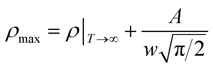 | (16) |
So, the Gauss function (14) will be rewrite as:
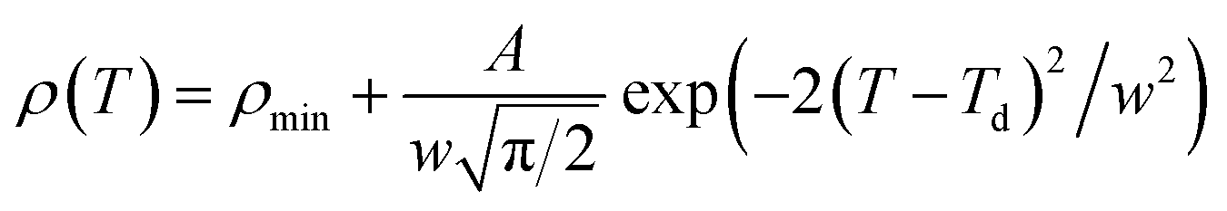 | (17) |
We analyses the resistivity curves of LSSMIO compound at different magnetic field using the above approach (17). Optimized parameters employed to simulate the component spectra are also listed in Table 4 and the fitted curves are shown in Inset. a Fig. 6.
| Calculated Gauss function | R2 | |
|---|---|---|
| La0.5Sm0.1Sr0.4Mn0.975In0.025O3 0T | 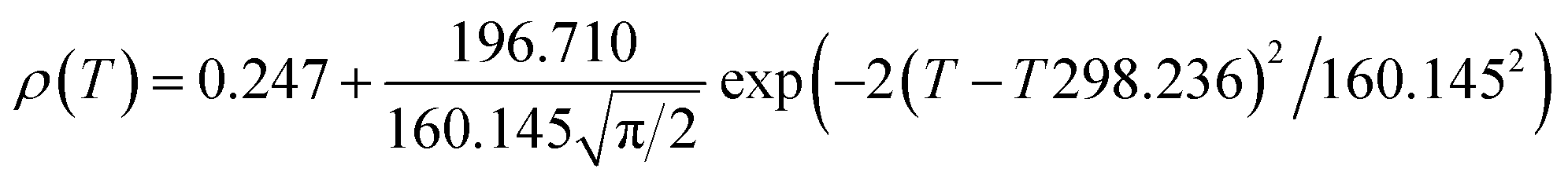 |
0.997 |
| La0.5Sm0.1Sr0.4Mn0.975In0.025O3 1T | 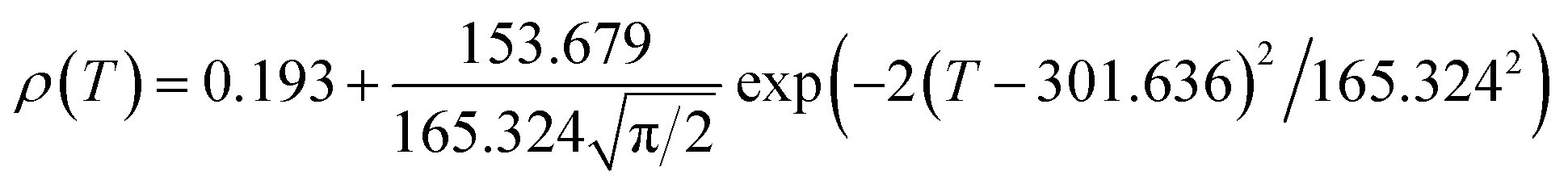 |
0.989 |
| La0.5Sm0.1Sr0.4Mn0.975In0.025O3 2T | 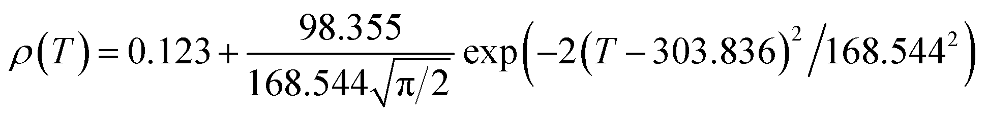 |
0.998 |
| La0.5Sm0.1Sr0.4Mn0.975In0.025O3 3T | 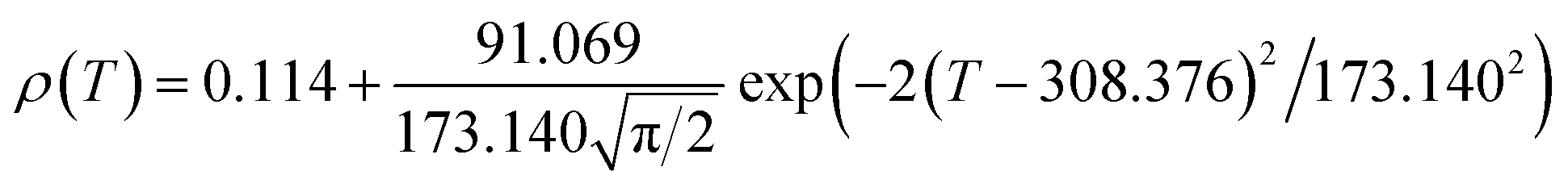 |
0.996 |
| La0.5Sm0.1Sr0.4Mn0.975In0.025O3 4T | 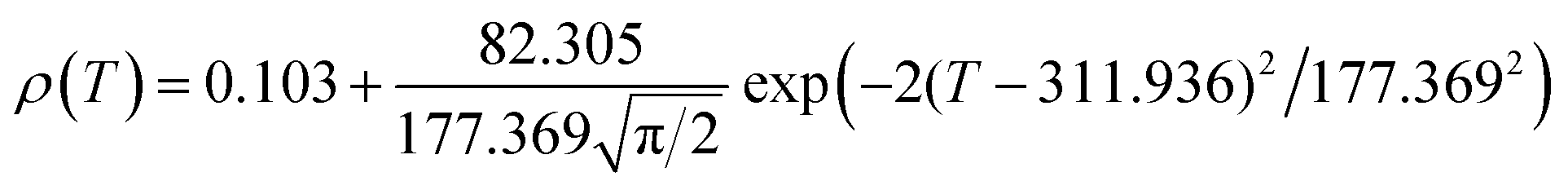 |
0.987 |
| La0.5Sm0.1Sr0.4Mn0.975In0.025O3 5T | 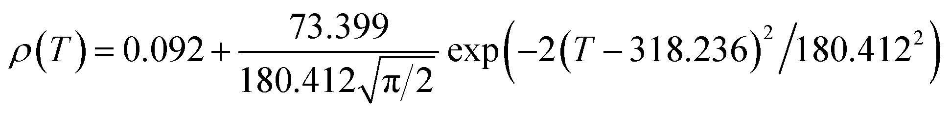 |
0.995 |
The correlation coefficient R2 (Table 4) which is close to 1, showed a satisfactory agreement between experimental and the modeled data which implies that the metal–insulator transition temperature, TM–Sc can be confirmed more precisely by the Gauss function simulation for our compound. The comparison between the peaks of the best-fitted value of Td, determined from Gauss function, and the experimental data demonstrated that parameter Td corresponds to the metal–semiconducting transition temperature, TM–Sc.
Thus, the transition temperature TM–Sc can be confirmed more precisely for other magnetic fields using the appropriate Gauss function simulation.
The Fig. 7 illustrates the dependency of ρmax on the applied magnetic field for LSSMIO sample. The best fit of this curve show that the successful logistics equation could properly give a quantitative relationship between ρmax and magnetic field μ0H via nonlinear curve fitting, and the logistic function is given by:
 | (18) |
 | ||
| Fig. 7 Experimental and simulated ρmax as a function of magnetic field. The inset shows TM–Sc vs. μ0H for LSSMIO compound. | ||
The optimized parameters A, B, C and P will be determined from the fitting of the experimental data (Table 5).
| A | B | C | P | S | I | |
|---|---|---|---|---|---|---|
| La0.5Sm0.1Sr0.4Mn0.975In0.025O3 | 0.426 | −0.265 | 1.231 | 2.632 | 3.628 | 296.095 |
The plots of ρmax versus magnetic field for LSSMIO compound have been fitted with the logistic model, which successfully describes the experimental behavior of the maximum resistivity ρmax of our sample. According to this model, it's clear that ρmax decreases with an increased magnetic field μ0H, which implies a logistic increase in the carrier density. For this reason, it is appropriate to use the logistic model for predicting the maximum resistivity ρmax before one magnetic field is applied.
It's clear from Fig. 6 that TM–Sc shifts toward higher temperatures when μ0H increases, which confirm that there is a relationship between TM–Sc and the applied magnetic field. Inset. Fig. 7 shows the construct of the TM–Sc of LSSMIO compound as a function of applied magnetic field. We can see that there is a linear relationship between the two variables.
Therefore, the functional form between TM–Sc and magnetic field is expressed by a line eqn (19), and it is given by:
| TM–Sc(μ0H) = S × μ0H + I | (19) |
The obtained constants are illustrated in Table 5. Notably, it can be observed that the theoretical results of TM–Sc derived by eqn (19) are consistent with the experimental data in Table 4. Therefore, it may be stated that the magnetic field is correlative with TM–Sc. In addition, it is appropriate to use eqn (19) in forecasting TM–Sc before one magnetic field is applied.
The shifts of the TM–Sc to the high-temperature range with the increase of the applied magnetic field can be explained by the reduction in the charge carriers delocalization uniformly caused by the applied magnetic field, which in turn might result in reducing the resistivity and also cause local ordering of the magnetic spins in the same way. Due to this linear ordering, the FM metallic state may suppress the PM insulating regime. Therefore, it may be stated that the conduction electrons (eg1) are completely polarized inside the magnetic domains hence, the peak temperature (TM–Sc) shifts to the high temperature side with applications of the magnetic field.
3.4. Study of magnetoresistance
The magnetoresistance MR is a fundamental property of manganites, which is related to the reduction of the electrical resistivity of the material by applying a magnetic field, it is given by:
 | (20) |
Inset b Fig. 6 presents the variation of MR as a function of the temperature at different applied magnetic fields (2–5T). It is very interesting to note from this figure that MR presents a pic around TC then it gradually decreases at high temperatures. The maximum magnetoresistance values of our compound at the metal–semiconducting (MSc) transition temperature are found 52%, 58%, 63% and 69% under applied magnetic field of 2, 3, 4 and 5T, respectively.
The reason for the higher MR% observed at high temperature is attributed to the involved spin polarized tunneling between grains or spin dependent scattering of polarized electron at grain boundaries.41,42
3.5. Critical behavior
For a continuous phase transition around the critical temperature, its thermodynamic function can be expressed by a power law form with three critical exponents. We would like to make a brief mention of the definitions of these exponents, namely β (associated with the spontaneous magnetization MS), γ (associated with initial susceptibility χ0−1) and δ (associated with the critical magnetization isotherm (magnetization M versus magnetic field μ0H at TC).8,43 The mathematical definitions of the exponents from magnetization measurements are given in the following relations:| Ms(T) = M0|ε|−β, ε < 0, T < TC | (21) |
|
χ0−1(T) = (h0/M0)εγ, ε > 0, T > TC
| (22) |
| M = DH1/δ, ε = 0, T = TC | (23) |
In our work, we have used different methods to investigate the critical behavior of the LSSMIO sample, namely the modified Arrott plots (MAP) method, the Kouvel–Fisher method (KF) and critical isotherm analysis (CI).44,45 The first method used to calculate the critical exponents is the MAP method (also called Arrott–Noakes plots). In this technique, the M = f (μ0H) data is converted into series of isothermal (M1/β vs. (μ0H/M)1/γ) depending on the following relation:44
| (μ0H/M)1/γ = (T − TC)/T1 + (M/M1)1/β | (24) |
Fig. 8(a–c) shows the modified Arrott plots (MAP) based on the Arrott–Noakes equation of state eqn (24), at different temperatures by using the 3D Ising model (β = 0.325, γ = 1.240), the 3D Heisenberg model (β = 0.365, γ = 1.336) and the tricritical mean field (β = 0.25, γ = 1), respectively for LSSMIO compound. In order to select the best model which describes this system, we calculated their relative slopes (RS) which are defined as: RS = S(T)/S(TC) (where S(T) is the slope of the quasi-straight line in the high-field region at T). In the most ideal case, all RSs should be equal to 1 because the modified Arrott plot is a series of parallel straight lines.
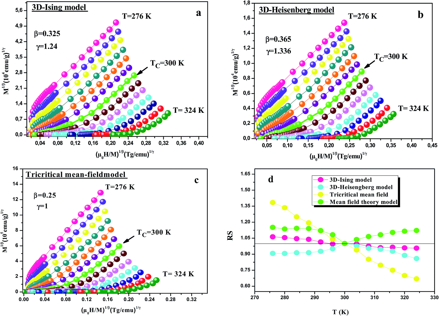 | ||
| Fig. 8 Modified Arrott plot isotherms of M1/β vs. (μ0H/M)1/γ for LSSMIO sample, with (a) 3D Ising-model (β = 0.325 and γ = 1.24); (b) 3D Heisenberg model (β = 0.365 and γ = 1.336); (c) tricritical mean-field model (β = 0.25 and γ = 1) and (d) shows the relative slope (RS) as a function of temperature using several methods. | ||
Fig. 8(d) shows the RS vs. T curve for LSSMIO sample for the four models, mean field model, 3D-Heisenberg, 3D-Ising and tricritical mean field model. The RS of 3D-Heisenberg and tricritical mean-field models obviously deviates from the straight line of RS = 1 but the RS of 3D-Ising model is around to this line. Therefore, the first Arrott plot gives the best results among these three models, indicating the critical properties of LSSMIO compound can be described with 3D-Ising model.
Based on these isotherms, the spontaneous magnetization MS(T, 0) and the inverse susceptibility χ0−1(T) data are extracted from the linear extrapolation from the high-field region to the intercepts with the axes M1/β and (μ0H)1/γ, respectively. In Fig. 9(a) we have plotted the temperature dependence of MS(T, 0) as green squares and χ0−1(T) as blue squares with their fitting curves using eqn (21) and (22), respectively. We find that the final fitted curves reproduce the experimental data perfectly and give two sets of critical exponents (Table 6). It can be seen that TC obtained from the critical analysis of the modified plot agrees well with that obtained from the M(T) curves in Fig. 3, and the obtained critical exponents are very close to those in the 3D Ising model.
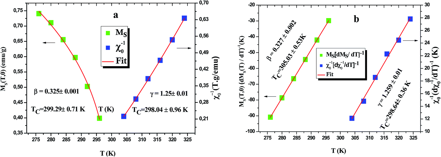 | ||
| Fig. 9 (a) Temperature dependences of the spontaneous magnetization MS(T) (left) and inverse initial susceptibility χ0−1(T) (right) for LSSMIO sample. (b) Kouvel–Fisher plots of MS(T)[dMS(T)/dT]−1 (left) and χ0−1(T)[dχ0−1(T)/dT]−1 vs. T (right) of LSSMIO sample. | ||
 , δ exp: the δ values obtained by critical isotherm (CI) fitting)
| Material | Method | TC (K) | β | γ | δ | Ref. |
|---|---|---|---|---|---|---|
| Mean-field model | Theory | 0.5 | 1.0 | 3.0 | 49 | |
| 3D-Heisenberg model | Theory | 0.365 ± 0.003 | 1.336 ± 0.004 | 4.80 ± 0.04 | 49 | |
| 3D-Ising model | Theory | 0.325 ± 0.002 | 1.241 ± 0.002 | 4.82 ± 0.02 | 49 | |
| Tricritical mean-field model | Theory | 0.25 | 1 | 5 | 50 | |
| La0.5Sm0.1Sr0.4Mn0.975 In0.025O3 | MAP | 298.66 ± 0.64 | 0.325 ± 0.001 | 1.25 ± 0.01 | This work | |
| KF | 301.83 ± 0.43 | 0.327 ± 0.002 | 1.259 ± 0.001 | This work | ||
| CI (cal) | — | — | — | 4.84 | This work | |
| CI (exp) | — | — | — | 4.81 ± 0.01 | ||
| La0.7Ca0.2Sr0.1Mn0.85Cr0.15O3 | 234.54 ± 0.6 | 0.322 ± 0.03 | 1.2 ± 0.17 | 4.752 | 51 | |
| La0.6Sr0.4Mn0.9V0.1O3 | 356.407 | 0.316 | 1.243 | 4.947 | 52 | |
| La0.6Ca0.2Sr0.2MnO3 | 344.456 | 0.498 | 1.053 | 2.992 | 53 | |
| La0.57Nd0.1Sr0.33MnO3 | 352.23 | 0.368 | 1.191 | 4.236 | 54 | |
| La0.7Ca0.2Sr0.1MnO3 | 284 | 0.394 | 0.925 | 3.34 | 55 | |
| La0.75Sr0.25MnO3 | — | 0.40 ± 0.02 | 1.27 ± 0.06 | 4.12 ± 0.33 | 56 | |
| La0.7Sr0.3MnO3 | 360.2 | 0.377 ± 0.004 | 1.168 ± 0.006 | 4.10 ± 0.01 | 57 | |
| La0.7Sr0.3Mn0.95Co0.05O3 | 320.4 | 0.403 ± 0.005 | 1.159 ± 0.007 | 3.88 ± 0.01 | 57 | |
| La0.7Sr0.3Mn0.9Co0.1O3 | 281.6 | 0.457 ± 0.007 | 1.114 ± 0.005 | 3.44 ± 0.01 | 57 | |
| La0.7Sr0.3Mn0.85Co0.15O3 | 273.9 | 0.418 ± 0.004 | 1.187 ± 0.006 | 3.84 ± 0.01 | 57 | |
| La0.5Sm0.1Sr0.4MnO3 | 313.36 ± 0.36 | 0.324 ± 0.01 | 1.240 ± 0.13 | 4.83 ± 0.01 | 58 |
As the next step in the scaling analysis, we have followed the Kouvel Fisher method to determine more accurately β, γ and TC.47
| MS(T)[dMS(T)/dT]−1 = (T − TC)/β | (25) |
| χ0−1(T)[dχ0−1(T)/dT]−1 = (T − TC)/γ | (26) |
After this method both MS[dMS/dT]−1 and χ0−1[dχ0−1/dT]−1 have a linear behavior with respect to T with slopes 1/β and 1/γ, respectively, as shown in Fig. 9(b).
One of the advantages of this method is that the value of the critical temperature is not introduced a priori but extracted from the intercept of the straight fitted lines on the temperature axis. The values of β, γ and TC obtained by KF method are also summarized in Table 6.
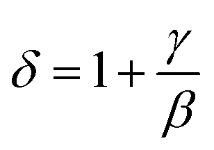
It is worth remarking how MAPs and the Kouvel Fisher method give close values of all critical parameters, confirming the robustness of the results. After eqn (23), the critical exponent δ can be extracted from the fitting of the critical isotherm to be compared with the values obtained from the scaling law (eqn (27)). Inset Fig. 10 shows the critical isotherm at T = 300 K in log–log scale as this should render a straight line (as it happens), whose slope is δ. We obtained δ = 4.81 ± 0.01 for LSSMIO compound (Table 6).
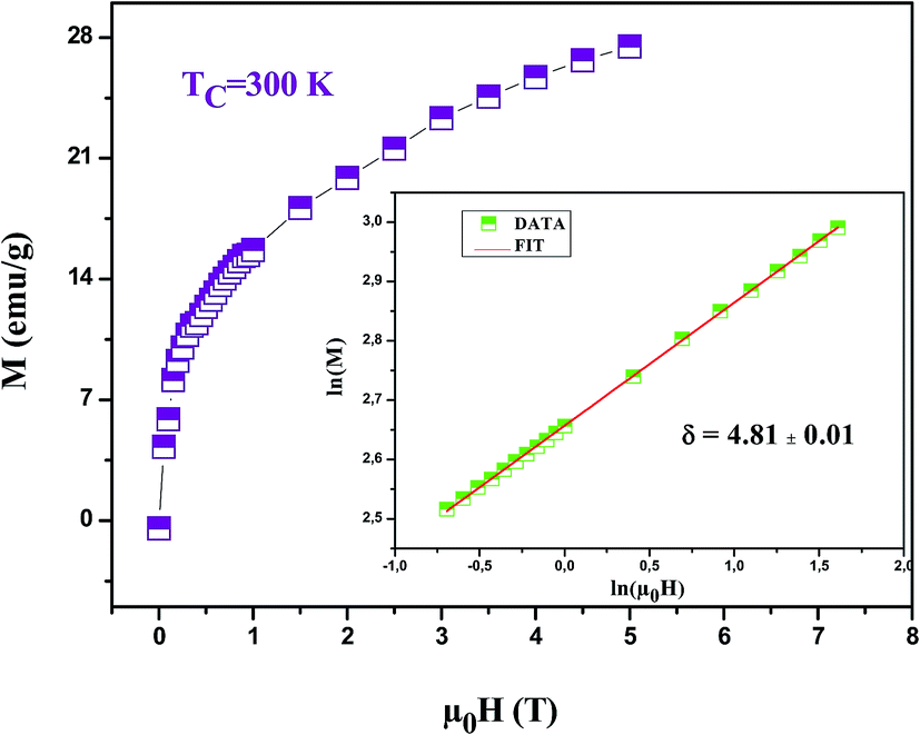 | ||
| Fig. 10 Isothermal M vs. μ0H plot of LSSMIO sample at TC = 300 K; the inset shows the same plot in log–log scale and the solid line (red color) is the linear fit following eqn (19). | ||
Furthermore, according to the statistical theory, these three critical exponents have to obey the Widom scaling relation:48
 | (27) |
Using this scaling relation, the value of δ is equal to 4.84 for β and γ obtained from the MAP method. Thus, the critical exponents found in this study obey the Widom scaling relation remarkably well, implying that the obtained β and γ values are reliable.
To put our obtained results in the context of previous works, we summarize in the Table 6 the values of the critical exponents obtained for our sample, those expected from theoretical models49,50 and the previous reports on Sr-doped manganites. It is found that the value of (β = 0.325 ± 0.001) for our compound is quite close to that expected from 3D Ising model (β = 0.325 ± 0.002). Similar results have been found for other compounds such as La0.7Ca0.2Sr0.1Mn0.85Cr0.15O3 (ref. 51) and La0.6Sr0.4Mn0.9V0.1O3 (ref. 52) with β = 0.322 ± 0.03 and β = 0.316, repectively. However, few other Sr-doped compounds, listed in Table 6, have β values close to those of the mean field and 3D Heisenberg models, such as La0.6Ca0.2Sr0.2MnO3 with (β = 0.498 and γ = 1.053),53 La0.57Nd0.1Sr0.33MnO3 with (β = 0.368 and γ = 1.191)54 and La0.7Ca0.2Sr0.1MnO3 with (β = 0.394 and γ = 0.925).55 Besides, the critical exponent values of La0.75Sr0.25MnO3 compound56 are all between mean-field values and three-dimensional-(3D)-Ising-model values (β = 0.40 ± 0.02, γ = 1.27 ± 0.06), but those determined for La0.7Sr0.3Mn1−xCoxO3 sample57 do not belong to any universality class (β = 0.403 ± 0.005; γ = 1.159 ± 0.007 for x = 0.05) and (β = 0.457 ± 0.007; γ = 1.114 ± 0.005 for x = 0.1). To further understand the magnetic interactions in In-doped perovskite manganite, in earlier studies we have carefully investigated the critical behavior of the reference compound La0.5Sm0.1Sr0.4MnO3 (ref. 58) (β = 0.324 ± 0.01; γ = 1.240 ± 0.13). It belong to the same universality class (3D Ising model) and it show that short-range ferromagnetic order is present in the reference compound around the critical temperature.
Performing a renormalization group analysis of exchange interaction systems, Fisher et al.59 have found that the values of the critical parameters depend on the range of exchange interactions with the form J(r) = 1/rd+σ (d and σ are the dimension of the system and the interaction range, respectively). It has been argued that, if σ is greater than 2, the Heisenberg framework is valid for a 3D-isotropic ferromagnet, However, if σ is less than 3/2, it is the mean field framework, which is valid. In the intermediate range of 3/2 ≤ σ ≤ 2 the FM behavior belongs to varied classes such as (3D Ising and tricritical mean field model) which depend on σ.
4. Conclusion
To sum up, it is worth emphasizing that we have studied the structural, magnetic, magnetocaloric and electrical properties of La0.5Sm0.1Sr0.4Mn0.975In0.025O3 perovskite manganite synthesized by sol–gel method. The experimental results have revealed that our sample crystallizes in a single phase with rhombohedral structure (Rc space group). A comprehensive and detailed critical behavior study of the ferromagnetic to paramagnetic transition in our manganite has been carried out using magnetic techniques in order to independently extract the critical exponents' β, γ, and δ. The results showed that the 3D Ising model is satisfied, indicating short range-interactions. On the other hand, the resistivity was fitted using the mathematical model (Gauss function). Besides, the resistivity of La0.5Sm0.1Sr0.4Mn0.975In0.025O3 was fitted well with the Gauss function. As far as, we have obtained a promising agreement between the theoretical and the experimental values of TM–Sc and ρmax. The magnetoresistance studies reveal that a high magnetic field has been found to affect MR at TC. For μ0H = 5 T, the maximum magnetic entropy change (−ΔSmaxM) of 5.25 J kg−1 K−1 and the relative cooling power (RCP) of 236 J kg−1 have been observed near the magnetic transition temperature 300 K. Thus, the broad operating temperature range with moderate values of −ΔSmaxM and RCP make our compound a potential candidate for magnetic refrigeration technology near room temperature.
Conflicts of interest
There are no conflicts to declare.References
- Z. Mohamed, E. Tka, J. Dhahri and E. K. Hlil, J. Alloys Compd., 2016, 688, 1260–1267 CrossRef CAS.
- R. N. Mahato, K. Sethupathi, V. Sankaranarayanan and R. Nirmala, J. Appl. Phys., 2010, 107, 09A943 CrossRef.
- A. M. Tishin and Y. I. Spichkin, The Magnetocaloric Effect and its Applications, IOP, Bristol and Philadelphia, 2003 Search PubMed.
- G. Mohamed Amara, Ah. Dhahri, J. Dhahri and E. K. Hlil, RSC Adv., 2017, 7, 10928 RSC.
- A. Zaidi, T. Alharbi, J. Dhahri, S. Alzobaidi, M. A. Zaidi and E. K. Hlil, Appl. Phys. A, 2017, 123, 94 CrossRef.
- U. L. Shinde, L. N. Singh and N. B. Srivastava, Phys. B, 2014, 452, 13 CrossRef CAS.
- C. Zener, Phys. Rev., 1951, 82, 403 CrossRef CAS.
- H. E. Stanley, Introduction to Phase Transitions and Critical Phenomena, Oxford University Press, London, 1971 Search PubMed.
- M. Seeger, S. N. Kaul, H. Kronmüller and R. Reisser, Phys. Rev. B: Condens. Matter Mater. Phys., 1995, 51, 12585 CrossRef CAS.
- Y. Motome and N. Furukawa, J. Phys. Soc. Jpn., 2001, 70, 1487 CrossRef CAS.
- Y. Motome and N. Furukawa, J. Phys. Soc. Jpn., 2000, 69, 3785 CrossRef CAS.
- K. Ghosh, C. J. Lobb, R. L. Greene, S. G. Karabashev, D. A. Shulyatev, A. A. Arsenov and Y. Mukovskii, Phys. Rev. Lett., 1998, 81, 4740 CrossRef CAS.
- Ch. V. Mohan, M. Seeger, H. Kronmuller, P. Murugaraj and J. Maier, J. Magn. Magn. Mater., 1998, 183, 348 CrossRef CAS.
- H. S. Shin, J. E. Lee, Y. S. Nam, H. L. Ju and C. W. Park, Solid State Commun., 2001, 118, 377 CrossRef CAS.
- H. M. Rietveld, J. Appl. Crystallogr., 1969, 2, 65 CrossRef CAS.
- V. M. Goldshmidt, Geochmische Verteilungsgesetze der Elemente, 1927–28, vol. VII–VIII Search PubMed.
- G. Caglioti, A. Paoletti and F. P. Ricci, Nucl. Instrum. Methods, 1960, 9, 195–198 CrossRef CAS.
- J. Gutiérrez, A. Peña, J. M. Barandiáran, J. L. Pizarro, T. Hernández, L. Lezama, M. Insausti and T. Rojo, Phys. B, 2000, 61, 9028–9035 Search PubMed.
- L. V. Bau, N. V. Khiem, N. X. Phuc, L. V. Hong, D. N. H. Nam and P. Nordblad, J. Magn. Magn. Mater., 2010, 322, 753 CrossRef CAS.
- H. S. Shin, J. E. Lee, Y. S. Nam, H. L. Ju and C. W. Park, Solid State Commun., 2001, 118, 377 CrossRef CAS.
- G. G. Lonzarich and L. Taillefer, J. Phys. C: Solid State Phys., 1985, 18, 4339 CrossRef CAS.
- E. Della Torre, L. H. Bennett and R. E. Watson, Phys. Rev. Lett., 2005, 94, 147210 CrossRef CAS PubMed.
- C. Bogdan Jurca, Synthèse et caractérisation de pérovskites doubles magnétorésistives dérivées de Sr2FeMoO6, PhD thesis, Université Paris Sud, Paris XI, 2004.
- S. de Brion, F. Ciorcas, G. Chouteau, P. Lejay, P. Radaelli and C. Chaillout, Phys. Rev., 1999, B59, 1304 Search PubMed.
- W. F. Giaugue and D. P. McDougall, Phys. Rev., 1933, 43, 768 CrossRef.
- H. Ishimoto, N. Nishida, T. Furubayashi, M. Shinohara, Y. Takano, Y. Miura and K. Ono, J. Low Temp. Phys., 1984, 55, 17 CrossRef CAS.
- Z. Mohamed, M. Abassi, E. Tka, J. Dhahri and E. K. Hlil, J. Alloy. Compd., 2015, 646, 23–31 CrossRef CAS.
- K. A. Gschneidner Jr, V. K. Pecharsky and A. O. Tsokol, Rep. Prog. Phys., 2005, 68, 1479 CrossRef.
- A. Dhahri, J. Dhahri, E. K. Hlil and E. Dhahri, J. Alloys Compd., 2012, 530, 1 CrossRef CAS.
- S. Mnefgui, A. Dhahri, N. Dhahri, E. K. Hlil and J. Dhahri, J. Magn. Magn. Mater., 2013, 340, 91 CrossRef CAS.
- V. K. Pecharsky, K. A. Gschneidner and A. O. Tsokol, Rep. Prog. Phys., 2005, 68, 1479 CrossRef.
- D. T. Morelli, A. M. Mance, J. V. Mantese and A. L. Micheli, J. Appl. Phys., 1996, 79, 373 CrossRef CAS.
- M. Foldeaki, R. Chahine and T. K. Bose, J. Appl. Phys., 1995, 77, 3528 CrossRef.
- H. Yang, Y. H. Zhu, T. Xian and J. L. Jiang, J. Alloys Compd., 2013, 555, 150 CrossRef CAS.
- X. X. Zhang, G. H. Wen, F. W. Wang, W. H. Wang and C. H. Yu, et al., Appl. Phys. Lett., 2000, 77, 3072 CrossRef CAS.
- M. Abassi, N. Dhahri, J. Dhahri and E. K. Hlil, Phys. B, 2014, 449, 138–143 CrossRef CAS.
- Y. Sun, W. Tong and Y. Zhang, J. Magn. Magn. Mater., 2001, 232, 205–208 CrossRef CAS.
- K. Dhahri, N. Dhahri, J. Dhahri, K. Taibi, E. K. Hlil, H. Belmabroukd and M. Zaidi, RSC Adv., 2017, 7, 43410 RSC.
- Q. Y. Dong, H. W. Zhang, J. R. Sun, B. G. Shen and V. Franco, J. Appl. Phys., 2008, 103, 116101 CrossRef.
- L. Changshi, J. Chem. Eng. Data, 2011, 56, 2 CrossRef.
- G. Venkataiah, V. Prasad and P. V. Reddy, J. Alloys Compd., 2007, 429, 1–9 CrossRef CAS.
- D. S. Rana, K. R. Mavani, C. M. Thaker, D. G. Kuberkar, C. D. Kundaliya and S. K. Malik, J. Magn. Magn. Mater., 2004, 271, 215–223 CrossRef CAS.
- S. Rößler, U. K. Rößler, K. Nenkov, D. Eckert, S. M. Yusuf, K. Dörr and K.-H. Mülle, Phys. Rev. B: Condens. Matter Mater. Phys., 2004, 70, 104417 CrossRef.
- A. Arrot and J. E. Noakes, Phys. Rev. Lett., 1967, 19, 786 CrossRef.
- B. Widom, J. Chem. Phys., 1965, 43, 3898 CrossRef.
- S. K. Banerjee, Phys. Lett., 1964, 12, 16 CrossRef.
- J. S. Kouvel and M. E. Fisher, Phys. Rev., 1964, 136, A1626 CrossRef.
- H. S. Shin, J. E. Lee, Y. S. Nam, H. L. Ju and C. W. Park, Solid State Commun., 2001, 118, 377 CrossRef CAS.
- S. N. Kaul, J. Magn. Magn. Mater., 1985, 53, 5 CrossRef CAS.
- M. Pękała, J. Appl. Phys., 2010, 108, 113913 CrossRef.
- W. Chen, L. Y. Nie, W. Zhong, Y. J. Shi, J. J. Hu, A. J. Li and Y. W. Du, J. Alloy. Compd., 2005, 395, 23–25 CrossRef CAS.
- Z. B. Guo, Y. W. Du, J. S. Zhu, H. Huang, W. P. Ding and D. Feng, Phys. Rev. Lett., 1997, 78, 1142 CrossRef CAS.
- M. Nasri, M. Triki, E. Dhahri and E. K. Hlil, J. Alloys Compd., 2013, 546, 84–91 CrossRef CAS.
- S. Mnefgui, A. Dhahri, N. Dhahri, E. K. Hlil and J. Dhahri, Solid State Sci., 2013, 21, 19 CrossRef CAS.
- T.-L. Phan, Y. D. Zhang, P. Zhang, T. D. Thanh and S. C. Yu, J. Appl. Phys., 2012, 112, 093906 CrossRef.
- D. Kim, B. L. Zink, F. Hellman and J. M. D. Coey, Phys. Rev. B: Condens. Matter Mater. Phys., 2002, 65, 214424 CrossRef.
- T. D. Thanh, D. C. Linh, T. V. Manh, T. A. Ho, T.-L. Phan and S. C. Yu, J. Appl. Phys., 2015, 117, 17C101 CrossRef.
- M. Dhahri, J. Dhahri and E. K. Hlil, J. Magn. Magn. Mater., 2017, 434, 100–104 CrossRef CAS.
- M. E. Fisher, S.-K. Ma and B. G. Nickel, Phys. Rev. Lett., 1972, 29, 917–920 CrossRef.
| This journal is © The Royal Society of Chemistry 2018 |