DOI:
10.1039/C7RA12602F
(Paper)
RSC Adv., 2018,
8, 7800-7809
A polyethersulfone–bisphenol sulfuric acid hollow fiber ultrafiltration membrane fabricated by a reverse thermally induced phase separation process
Received
20th November 2017
, Accepted 12th February 2018
First published on 19th February 2018
Abstract
A novel antifouling polyethersulfone (PES) hollow fiber membrane was modified by the addition of bisphenol sulfuric acid (BPA-PS) using a reverse thermally induced phase separation (RTIPS) process. BPA-PS was synthesized by click chemistry and was blended to improve the hydrophilicity of PES hollow fiber membranes. The performance of PES/BPA-PS hollow fiber membranes, prepared with different contents of BPA-PS and at different temperatures of the coagulation water bath, was characterized by scanning electron microscopy (SEM), pure water flux (Jw), BSA rejection rate (R), atomic force microscopy (AFM), X-ray photoelectron spectroscopy (XPS), Fourier transform infrared spectroscopy (FTIR) and water contact angle measurements. SEM morphologies revealed that a finger-like cross-section emerged in the hollow fiber membrane by a non-solvent induced phase separation (NIPS) mechanism while a sponge-like cross-section appeared in the hollow fiber membrane via the RTIPS method. Both FTIR and XPS analysis indicated that the sulfate group in BPA-PS was successfully blended with the PES membranes. The results from AFM and water contact angle measurements showed that the surface roughness increased and the hydrophilicity of the PES/BPA-PS hollow fiber membrane was improved with the addition of BPA-PS. The results demonstrated that the PES/BPA-PS membrane with 1 wt% BPA-PS via RTIPS exhibited optimal properties.
1 Introduction
Owing to its advantages of moderate operation conditions, less energy consumption and environmental friendly properties, membrane separation techniques1–4 have become the most popular approach in water purification. Among a variety of membrane preparation methods, phase separation methods, which include the non-solvent induced phase separation method (NIPS)5–8 and thermally induced phase separation (TIPS) method,9–12 are widely used for membrane preparation with outstanding merits. During the NIPS process, the fast transfer of solvent and non-solvent leads to the phase separation, which is beneficial for the formation of a dense skin top surface, finger-like structure and poor mechanical properties.13–15 In the TIPS process, a homogeneous doping solution is prepared at high temperature and spun at room temperature.16,17 Nevertheless, the application of the TIPS procedure is limited by its requirement for high temperature and fewer options of appropriate diluents.
As a novel method to control phase separation, reverse thermally induced phase separation (RTIPS), which is the lower critical solution temperature (LCST)-TIPS process,18 combines advantages of both low temperature in dope solutions preparation (similar to NIPS) and the fast rate of heat transfer (similar to TIPS). Compared to NIPS method, the structure of the membrane formed from RTIPS transforms the finger-like structure into sponge-like structure. In the meantime, the dense skin layer turns into the porous layer. The sponge-like structure accelerates the rate of BSA rejection and provides excellent mechanical properties, while porous surface contributes to high pure water flux. Contrast with TIPS, dopes are obtained at room temperature and spun at a temperature higher than cloud point, which could reduce the energy consumption and makes it more conducive to industrialization. In a word, RTIPS process is a cost-effective process and generates less waste. However, due to the membrane is more vulnerable to pollutants, the popularization and development of the membrane technology is severely hampered. In order to improve the antifouling property of the membrane, the modification is necessary.19 Zhao et al.20 added HBPE into PSF membrane via RTIPS method, then both the antifouling property and water permeate rate were improved to a great extent. Liu et al.21 prepared PES/TiO2 hybrid membrane through sol–gel process by the assistant of RTIPS method. Thus, the antifouling property of the membrane was enhanced with the addition of TiO2.
PES hollow fiber membranes need to be fabricated to achieve excellent properties. Among the modified methods, blending approach is a simple and useful route to prepared PES membrane. Daraei et al.22 mixed various types of polymers to modify multi-walled carbon nanotubes to improve the antifouling capability of PES membrane. Li et al.23 added SPES into PES hollow fiber membrane to improve the anti-pollution properties. However, the process and mechanism are more complex to form a membrane in these approaches. Click chemistry offers a terrific way for membrane modification.24–28 The prominent merits of click chemistry are its capacity to supply superior site selectivity, which can provide almost quantitative conversion under mild condition and with almost no side reaction or by-product.29–31 Ge et al.32 constructed an ionic highway in the anion-exchange membrane by click chemistry and synthesized a novel AEMs material. Zheng et al.33 developed an antifouling silicon surface with improving the hemocompatibility by click chemistry, and found that the antifouling property enhanced in an artificial kidney equipment. Besides, the modification of polyethersulfone membrane with BPA-PS by RTIPS method has not been reported in the literature. Thus, a novel approach was proposed to introduce the click sulfuric acid functional group into polyethersulfone membrane. It is very interesting to point out that the click sulfuric acid functional group in bisphenol A poly sulfuric acid (BPA-PS)34 may facilitate the antifouling performance in the polyethersulfone membrane. As a new antifouling material, BPA-PS (synthesized by click reaction) not only displays excellent antifouling property against protein fouling but also provides an effective approach to modify the polyethersulfone membrane.
To investigate the polyethersulfone membrane modified by BPA-PS further, the effects of coagulation water bath temperature and the quantity of BPA-PS on membrane formation mechanism, membrane structure, membrane filtration performance as well as fouling resistance were investigated in this work.
2 Experimental
2.1 Materials
Polyethersulfone (PES, Mw = 45![[thin space (1/6-em)]](https://www.rsc.org/images/entities/char_2009.gif) 000) was purchased from BASF Co. Ltd. (German). PES was used for membrane preparation after dried about 24 h at 333 K. N,N-Dimethyl acetamide (DMAC), diethylene glycol (DEG) were provided by Shanghai Chemical Reagent Co. Ltd. Bisphenol sulfuric acid (BPA-PS, Mw = 97
000) was purchased from BASF Co. Ltd. (German). PES was used for membrane preparation after dried about 24 h at 333 K. N,N-Dimethyl acetamide (DMAC), diethylene glycol (DEG) were provided by Shanghai Chemical Reagent Co. Ltd. Bisphenol sulfuric acid (BPA-PS, Mw = 97![[thin space (1/6-em)]](https://www.rsc.org/images/entities/char_2009.gif) 000) was provided by Shanghai Institute of Organic Chemistry, Chinese Academy of Sciences. Bovine serum albumin (BSA, Mw = 67
000) was provided by Shanghai Institute of Organic Chemistry, Chinese Academy of Sciences. Bovine serum albumin (BSA, Mw = 67![[thin space (1/6-em)]](https://www.rsc.org/images/entities/char_2009.gif) 000) was provided by Shanghai Lianguan Biochemical Engineering Co. Ltd. All of the pure water in this work was self-made.
000) was provided by Shanghai Lianguan Biochemical Engineering Co. Ltd. All of the pure water in this work was self-made.
2.2 Characterization of BPA-PS
The chemical structure of BPA-PS was characterized by FTIR (Nicolet 6700, Thermo Electron Scientific Instruments Corp.).
2.3 Preparation of dope solutions
The solvent (DMAc) and a certain amount of BPA-PS were premixed firstly in a conical flask about several hours, then measured amount of PES was dissolved in the conical flask at room temperature (about 293 K), finally, non-solvent (DEG) was added in the solution. The dope solutions degassed about 12 h at room temperature under atmospheric pressure for spinning. The composition of the dopes and the coagulation water bath temperatures were listed in Table 1 and 2, respectively.
Table 1 The compositions of dopes
| Dope no |
Composition of dope solution (wt%) |
| PES |
BPA-PS |
DMAc |
DEG |
| MBPA PS-1 |
17.00 |
0.00 |
43.00 |
40.00 |
| MBPA PS-2 |
17.00 |
0.50 |
42.75 |
39.75 |
| MBPA PS-3 |
17.00 |
1.00 |
42.48 |
39.52 |
| MBPA PS-4 |
17.00 |
1.50 |
42.28 |
39.27 |
| MBPA PS-5 |
17.00 |
2.00 |
41.97 |
39.03 |
Table 2 Coagulation water bath temperature
| Membrane no |
Water bath temperature (K) |
Membrane no |
Water bath temperature (K) |
| MBPA PS-1-50 |
323 |
MBPA PS-4-50 |
323 |
| MBPA PS-2-50 |
323 |
MBPA PS-5-50 |
323 |
| MBPA PS-3-50 |
323 |
MBPS PS-3-20 |
293 |
2.4 Preparation of hollow fiber membrane
The preparation process of the PES hybrid hollow fiber membrane by wet-spinning method was illustrated in Fig. 1. Both the internal and external coagulation water bath were deionized water, the temperatures of the coagulation water bath were listed in Table 2. The dope solution flow rate, bore fluid rate and spinning flow rate were constant. These prepared membranes were immersed in deionized water about 3 d which were refreshed every day to remove the remnant solvent in the hollow fiber membranes, then the hollow fiber membranes were immersed in glycerol aqueous solution 3 d and were dried in air at room temperature for testing.
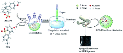 |
| | Fig. 1 Preparation illustration of the PES/BPA-PS membrane. | |
2.5 Measurement of light transmittance
The experiment of light transmittance was operated via a self-made device.35 A collimated laser was directed into a glass sheet which was immersed in water bath rapidly at fixed temperature. The message of light intensity was captured via a light detector and was recorded in computer. The precipitation rate of dopes was characterized by the curve of light transmittance to immersion time.
2.6 Cloud point measurement
The cloud point measurement was performed in order to confirm the phase separation temperature (i.e., LCST, which was defined as cloud point) of dopes.18 The cloud points of dopes were measured via a self-made device. Briefly, the dope solution was inserted between two cover slips which were heated on a hot stage (KEL-XMT-3100, Shanghai Weitu Optics and Electron Technology Co. Ltd.) from 293 K to 373 K at 1 K min−1. A collimated laser was directed on coverslips, then the light intensity, which was captured by a light detector, was recorded on the computer. The intensity of transmitted light decreased rapidly with the phase separation occurred. The change of the signal was considered as the indication of cloud point.
2.7 SEM measurement
Morphologies (top surface and cross section) of hollow fiber membranes were visualized via a scanning electron microscope (SEM; Nova NanoSEM, USA). The cross-sections of the membranes were broken in liquid nitrogen. Each sample was coated with gold in vacuum environment.
2.8 Permeation measurement
The pure water flux (Jw) and BSA rejection rate (R) of hollow fiber membranes were measured by a self-made device.36 All tests were executed at room temperature along with a successive pressure (0.1 MPa). The Jw, R of the hollow fiber membranes, which were evaluated precisely using deionized water and BSA aqueous solution (300 mg L−1), were calculated based on the following eqn (1) and (2), respectively.| |
 | (1) |
| |
 | (2) |
where Jw is the pure water flux (L m−2 h−1), A is the effective membrane area (m2), Q is the permeate volume (L), t is the permeate time (h), R, Cp and CF were the BSA rejection rate (%), permeate and feed solutions (wt%), respectively.
2.9 Porosity and size measurement
The membrane porosity ε (%) was evaluated by gravimetric method using the following equation:| |
 | (3) |
where ε, W1, W2, ρ1 and ρ2 are the porosity of the membrane, wet membranes weight, dry membranes weight, water density and the polymer (PES) density, respectively.
Mean pore radius rm (μm) of the membrane was defined according to the formula of Guerout–Elford–Ferry:36
| |
 | (4) |
where
η is the viscosity of water (8.9 × 10
−4 Pa s
−1),
h is the thickness of the membrane (mm), Δ
P is the operate pressure (0.1 MPa).
Maximum pore size rmax (μm) of the membrane could be obtained through bubble point procedure referring to the Laplace's equation:37
| |
 | (5) |
where
σ,
θ,
P are the water surface tension (22.8 × 10
−3 N m
−1), the contact angle (°) of the membrane and the minimum bubble point pressure (MPa), respectively.
2.10 Water contact angle measurement
The contact angle (θ) was acquired by the device (JC2000A, Shanghai Zhongcheng Digital Equipment Co. Ltd., China) at room temperature. Briefly, the camera capturing image obtained when droplet fell on the surface of the membrane as well as sample contact angle was recorded in computer. Every sample was measured four times and then averaged.
2.11 AFM measurement
Atomic force microscopy (Veeco, NanoscopeIIIa Multimode AFM) with 5 mm × 5 mm scanning size was employed to examine the roughness of the membrane. The AFM figure was managed by Gwyddion software, moreover, the roughness of the membrane was analysed by NanoScope analysis software.
2.12 XPS measurement
X-ray photoelectron spectroscopy analysis (XPS; VG Microlab II, UK) was used for determining chemical composition of the membrane.
2.13 Antifouling measurement
A dead end filtration experiment was performed to examine the long-term antifouling property of the membrane further.38 Briefly, membrane pure water flux (Jw1, L m−2 h−1) was obtained at 0.1 MPa. Afterwards, BSA solution (300 mg L−1) was permeated through the tested membrane to achieve the BSA flux (Jp1, L m−2 h−1) followed by washing the tested membrane by chemical process. The experiment repeated twice. The FRR (%) of the membrane, which obtained according to the permeation fluxes, was defined by the following formula (6). The pure water flux and BSA flux with time also obtained to illustrate the anti-pollution properties of the membranes further.| |
 | (6) |
3 Results and discussion
3.1 Characterization of BPA-PS
The synthetic pathway and the FTIR spectrum of BPA-PS were displayed in Fig. 2 and 3, respectively. In Fig. 2, the click reaction occurred between the –SO3F and –OTBS at 120 °C about 1.5 h, then the –SO4– generated. As shown in Fig. 3, the absorption peak at 1150.1 cm−1 represented the symmetrical stretching vibrations of the S![[double bond, length as m-dash]](https://www.rsc.org/images/entities/char_e001.gif) O in the sulfuric acid group. In addition, the absorption peak at 878.5 cm−1 represented the stretching vibrations of the C–O–S in the sulfuric acid group. These results indicated that BPA-PS molecules had a high hydrophilicity group.
O in the sulfuric acid group. In addition, the absorption peak at 878.5 cm−1 represented the stretching vibrations of the C–O–S in the sulfuric acid group. These results indicated that BPA-PS molecules had a high hydrophilicity group.
 |
| | Fig. 2 The synthetic route of BPA-PS by click chemistry. | |
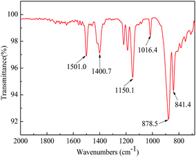 |
| | Fig. 3 The FTIR spectra of BPA-PS. | |
3.2 Cloud point
For the LCST dope solution which composed of PES/BPA-PS/DMAc/DEG, phase separation occurred when the temperature of the dope solution increased to the cloud point.
3.3 Cloud point
For the LCST dope solution which composed of PES/BPA-PS/DMAc/DEG, phase separation occurred when the temperature of the dope solution increased to the cloud point. The dope solution was thermodynamically stable at room temperature, while the interaction between the mixed polymer and solvent became increasingly weak with the increased coagulation bath temperature. Thus, the phases separated when the temperature reached cloud point. The influence of the BPA-PS from 0 wt% to 2 wt% on the cloud point was not obvious, and the cloud point was about 313 K.
3.4 Viscosity and light transmittance
Fig. 4 revealed the rate of light transmittance and the viscosity of the dope solutions. The viscosity in Fig. 4 indicated that the viscosity increased and exhibited a shear-thinning phenomenon in the presence of BPA-PS. This phenomenon became more pronounced when the mass ratio of BPA-PS increased from 0 wt% to 2 wt%. Moreover, Fig. 4 illustrated that the transmittance curve descended speedily at the initial stage and was accelerated with the addition of BPA-PS. In general, high viscosity39 would decrease the precipitated speed, however, the rate of phase separation was accelerated by the increased viscosity. This phenomenon could be explained through that the membranes formation mechanism was dominated via RTIPS process when the coagulation bath temperature was higher than the cloud point, and the speed of heat transfer was much higher than the mass transfer under the RTIPS mechanism. For this reason, the transmittance curve descended speedy at the initial stage and was accelerated with the increased BPA-PS.
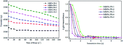 |
| | Fig. 4 The viscosity and light transmittance curves of the dopes with BPA-PS. | |
3.5 XPS analytical result of PES/BPA-PS hollow fiber membrane
XPS results of MBPA PS-1-50 and MBPA PS-3-50 were illustrated in Fig. 5 and Table 3. There were three broaden peaks at 172 eV, 296 eV and 536 eV in the blank PES membrane (Fig. 5a) which represented S2p, C1s and O1s regions, respectively. O1 score-level spectrum of the membrane included two peaks at 531.8 eV and 533.3 eV, which corresponding represented O![[double bond, length as m-dash]](https://www.rsc.org/images/entities/char_e001.gif) S and O–C. It was worth noting that a new peak appeared at 532.3 eV, which represented that O–S appeared in the PES/BPA-PS membrane (Fig. 5d). The appearance of the new peak showed that the PES/BPA-PS membranes had already blended with BPA-PS.
S and O–C. It was worth noting that a new peak appeared at 532.3 eV, which represented that O–S appeared in the PES/BPA-PS membrane (Fig. 5d). The appearance of the new peak showed that the PES/BPA-PS membranes had already blended with BPA-PS.
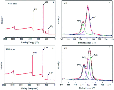 |
| | Fig. 5 (a and c) Wide scan of MBPA PS-1-50 and MBPA PS-3-50, (b and d) O1s region of MBPA PS-1-50 and MBPA PS-3-50. Coagulation temperature was 323 K. | |
Table 3 Elementary compositions of PES/BPA-PS hollow fiber membranes
| Sample |
Atom percent (%) |
| C |
O |
S |
H |
| MBPA PS-1-50 |
69.79 |
21.47 |
5.71 |
3.03 |
| MBPA PS-3-50 |
69.76 |
22.13 |
6.30 |
1.81 |
3.6 Membrane structure of PES/BPA-PS hollow fiber membrane
SEM images of the membranes were exhibited in Fig. 6 and 7, respectively. The working mechanism of the dopes underwent NIPS process when the coagulation bath temperature was lower than the cloud point while RTIPS took an effective effect when coagulation bath temperature was higher than the cloud point. As illustrated in Fig. 6, the finger-like structure could be found in the MBPA PS-3-20 (by NIPS) while the sponge-like structure was shown in MBPA PS-3-50 (by RTIPS). Owing to the common rule that thermodynamically low stability of dopes and the hydrophilicity of BPA-PS strengthened the precipitating rate by facilitating the inflow rate of pure water, then led to the formation of finger-like structures in MBPA PS-3-20. On the other hand, as it widely known that the speed of heat transfer is much higher than the rate of mass transfer, then the heat transfer is the major driving force in membrane formation procedure. Thus, when the coagulation bath temperature is higher than the cloud point (RTIPS process), the finger-like structure turns into sponge-like structure in MBPA PS-3-50.
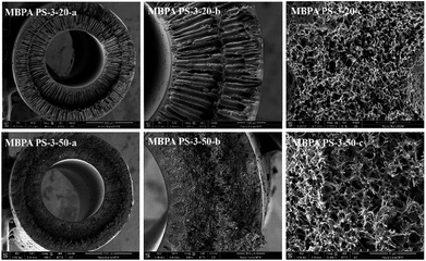 |
| | Fig. 6 SEM micrographs of MBPA PS-1-20 and MBPA PS-1-50. (a) Full cross-section (magnification 100×); (b) part cross-section (magnification 350×); (c) enlarge cross-section (magnification 10![[thin space (1/6-em)]](https://www.rsc.org/images/entities/char_2009.gif) 000×). 000×). | |
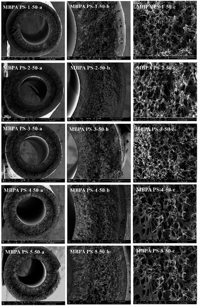 |
| | Fig. 7 SEM micrographs of the membranes with BPA-PS. Coagulation water bath temperature was 323 K. (a) Full cross-section (magnification 100×); (b) part cross-section (magnification 350×); (c) enlarge cross-section (magnification 10![[thin space (1/6-em)]](https://www.rsc.org/images/entities/char_2009.gif) 000×). 000×). | |
As shown in Fig. 7, the cross-sections of the membranes varied with the addition of BPA-PS when coagulation water bath temperature was fixed at 323 K. MBPA PS-1-50 showed the macroporous structure (MBPA PS-1-50-a) and dense cross-section (MBPA PS-1-50 b) under SEM images which indicated the rapid exchange of solvent and non-solvent during the membrane formation procedure. To investigate the influence of BPA-PS on the formation of various morphologies, SEM photographs, as shown in Fig. 7, turned dense cross-section and macroporous structure into sponge-like structure with the addition of BPA-PS. This could be explained by the increased viscosity of BPA-PS, which delayed the speed of phase separation and then sponge-like structure appeared in the membranes. Stratification in the middle of the membrane was ascribed to that the pure water transferred from interior and exterior to middle layer of the membrane simultaneously with fast transfer speed,40,41 and then led to pure water accumulated in the middle layer of the membrane. Finally, macroporous structure appeared in the cross-section of the membrane.
3.7 Pore size and porosity of PES/BPA-PS hollow fiber membrane
The porosity and pore size of the membranes were listed in Table 4, which varied with the addition of BPA-PS and membrane formation mechanism (NIPS or RTIPS). The porosity of the membranes MBPA PS-1-50, MBPA-PS-2-50, MBPA PS-3-50, MBPA PS-4-50 and MBPA PS-5-50, which prepared by RTIPS method, exhibited an increase first and then decreased trend with the addition of BPA-PS. Moreover, the porosity of the membranes with BPA-PS was higher than that of the blank PES membrane obviously. With regard to the membrane MBPA PS-3-20 and MBPA PS-3-50, the porosity increased when the formation mechanism of the membrane changed from NIPS to RTIPS. The porosity in Table 4 was uniform with the pure water flux and the BSA rejection rate in Fig. 10 and 11.
Table 4 Pore size and porosity of PES/BPA-PS membrane
| Membrane No |
BPA-PS (wt%) |
Coagulation bath temperature (K) |
Porosity (%) |
rmax (μm) |
rm (μm) |
| MBPA PS-1-50 |
0 |
323 |
80.3 ± 0.3 |
0.40 ± 0.03 |
0.083 ± 0.003 |
| MBPA PS-2-50 |
0.5 |
323 |
85.6 ± 0.5 |
0.41 ± 0.01 |
0.112 ± 0.011 |
| MBPA PS-3-50 |
1.0 |
323 |
86.7 ± 0.1 |
0.59 ± 0.01 |
0.109 ± 0.001 |
| MBPA PS-4-50 |
1.5 |
323 |
86.1 ± 0.5 |
0.56 ± 0.01 |
0.101 ± 0.004 |
| MBPA PS-5-50 |
2.0 |
323 |
86.3 ± 0.2 |
0.53 ± 0.01 |
0.097 ± 0.005 |
| MBPA PS-3-20 |
1.0 |
293 |
85.5 ± 0.2 |
0.51 ± 0.01 |
0.093 ± 0.007 |
As for the MBPA PS-3 series, the maximum pore size and mean pore size of the MBPA PS-3-50 (produced from RTIPS) were higher than the MBPA PS-3-20 (produced from NIPS), and this result matched with the SEM photographs in Fig. 6. For the membranes (MBPA PS-1-50, MBPA-PS-2-50, MBPA PS-3-50, MBPA PS-4-50 and MBPA PS-5-50) prepared via RTIPS method, the rmax and rm of the membrane with BPA-PS were higher than that of pure PES membranes due to the hydrophilicity of BPA-PS. For the MBPA-PS-2-50, MBPA PS-3-50, MBPA PS-4-50 and MBPA PS-5-50, the rmax and rm decreased with the increased BPA-PS, which was mainly caused by the high viscosity with the addition of BPA-PS.
3.8 AFM and water contact angle analysis of PES/BPA-PS hollow fiber membrane
Fig. 8 and Table 5 exhibited the three-dimensional AFM images and the roughness of the membranes. In the scan area 5 μm × 5 μm, the Ra of MBPA PS-1, MBPA PS-2, MBPA PS-3, MBPA PS-4 and MBPA PS-5 were 10.5 nm, 13.5 nm, 17.3 nm, 22.7 nm and 21.5 nm, respectively. The AFM image of the blank membrane, as illustrated in Fig. 8, was comparatively smooth. While the AFM images of the membrane became coarser with the increased BPA-PS. The anti-fouling property improved with the roughness because the pollutant accumulated in “Valley” in the membrane surface. BPA-PS, which increased the hydrophilicity of the membrane, also enhanced the adsorbance of contaminants on membrane than the blank PES membrane, and then improved the antifouling property of the membrane.
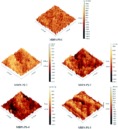 |
| | Fig. 8 AFM images of PES/BPA-PS hollow fiber membrane. Coagulation water bath temperature was 323 K. | |
Table 5 Roughness of PES/BPA-PS hollow fiber membrane
| Membrane no |
Ra (nm) |
Rms (nm) |
| MBPA PS-1 |
10.5 |
13.2 |
| MBPA PS-2 |
13.5 |
16.4 |
| MBPA PS-3 |
17.3 |
22.5 |
| MBPA PS-4 |
22.7 |
30.2 |
| MBPA PS-5 |
21.5 |
29.5 |
The water contact angle was metered by trailing the top surface of the membrane. As illustrated in Fig. 9, the static water contact angles of MBPA PS-1-50, MBPA PS-2-50, MBPA PS-3-50, MBPA PS-4-50 and MBPA PS-5-50 were 92.6°, 74.9°, 68.6°, 64.1° and 61.6°, respectively, which exhibited a decreasing trend with the increased BPA-PS. The presence of the hydroxyl group in BPA-PS and the transformation of BPA-PS to the top surface could explain the decreasing trend. As can be known that lower water contact angle is benefited for excellent anti-fouling property.42 Therefore, the addition of BPA-PS improved the hydrophilicity of the membrane.
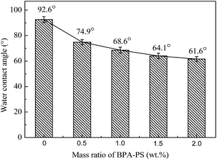 |
| | Fig. 9 The static water contact angles of PES/BPA-PS hollow fiber membrane. Coagulation temperature was 333 K. | |
3.9 Permeation performance of PES/BPA-PS hollow fiber membrane
The effect of BPA-PS and different temperatures of coagulation water bath on pure water flux and BSA rejection rate were displayed in Fig. 10 and 11, respectively. The pure water flux in Fig. 10, which the coagulation water bath temperature was set at 323 K, increased first and then decreased with BPA-PS. The increasing trend of pure water flux was attributed to the hydrophilicity group in BPA-PS while the decreasing trend was due to the increased viscosity by BPA-PS. These data were consistent with the mean pore size (rm) listed in Table 4 and water contact angle in Fig. 9. The optimum pure water flux (739 L m−2 h−1) and BSA rejection (79.2%) were obtained from the membrane with 1.0 wt% BPA-PS.
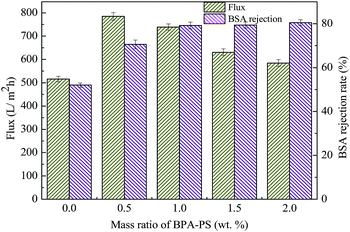 |
| | Fig. 10 The pure water flux and BSA rejection rate. Coagulation water bath temperature was 323 K. | |
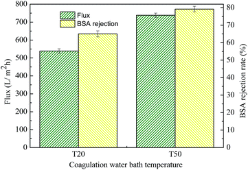 |
| | Fig. 11 The pure water flux and BSA rejection rate of MBPA-PS-1-20 and MBPA-PS-1-50. Coagulation water bath temperature was 323 K. | |
T20, T50, as shown in Fig. 11, were the coagulation water bath temperature. The phase separation process underwent NIPS method in T20 while the phase separation followed by RTIPS process in T50. It was evident that the pure water flux and BSA rejection rate of MBPA PS-1-50 which prepared by RTIPS method were higher than that of MBPA PS-1-20 by NIPS process. This phenomenon unanimous with that the dense skin top surface and the finger-like cross-section were obtained via NIPS while the porous top surface and the sponge-like cross-section were acquired by RTIPS. Porous top surface and sponge-like structure were conducive to high pure water flux and BSA rejection rate, respectively. This phenomenon was a convincing evidence for that RTIPS mechanism had the potential for high pure water flux and BSA rejection rate.
3.10 Antifouling property of PES/BPA-PS hollow fiber membrane
The FRR, pure water flux and BSA flux with time of the membranes were shown in Fig. 12 and 13, respectively. For the membranes prepared by RTIPS process, the FRR of the membranes with BPA-PS (MBPA PS-3-50, MBPA PS-5-50) was higher than the pure PES membrane (MBPA PS-1-50). This phenomenon was coincident with the test results of water contact angle and AFM. As for the changes of pure water flux and BSA flux with time, it decreased in the initial stage then changed little with time. The pure water flux and BSA flux with time of the MBPA PS-1-50, as illustrated in Fig. 12 and 13, displayed a faster descend trend than the MBPA PS-3-50 and MBPA PS-5-50. These changes illustrated the better antifouling performance of the membranes with BPA-PS.
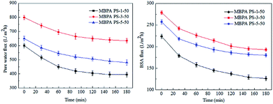 |
| | Fig. 12 The change of pure water flux and BSA flux with time. | |
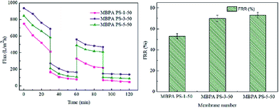 |
| | Fig. 13 The recycles and FRR of the membranes. | |
3.11 Comparison with other membranes
As listed in Table 6, the properties of the membranes in this paper were compared with other membranes in the literature. Both the high water flux and BSA rejection could be acquired via RTIPS (Fig. 10 and 11). Furthermore, the anti-fouling properties were improved by the addition of BPA-PS.
Table 6 The comparison with other membranes
| Membranes |
Preparation method |
Water bath temperature (K) |
Flux (L m−2 h−1) |
Re (%) |
Reference |
| PES/DMAC/DEG |
VIPS |
313 |
1090 ± 35 |
10 ± 0.3 (BSA, 67![[thin space (1/6-em)]](https://www.rsc.org/images/entities/char_2009.gif) 000) 000) |
41 |
| PES/Mg(OH)2/DMAC |
NIPS |
298 |
700 ± 45 |
90 ± 2.7 (BSA, 67![[thin space (1/6-em)]](https://www.rsc.org/images/entities/char_2009.gif) 000) 000) |
43 |
| PVDF/WA/DMAC |
NIPS |
298 |
70.6 ± 5 |
81 ± 2.1 (BSA, 67![[thin space (1/6-em)]](https://www.rsc.org/images/entities/char_2009.gif) 000) 000) |
44 |
| PES/PDMAEMA-b-PES-b-PDMAEMA |
NIPS |
298 |
145 ± 9 |
70 ± 2.1 (BSA,67![[thin space (1/6-em)]](https://www.rsc.org/images/entities/char_2009.gif) 000) 000) |
45 |
| PES/P(H–P–A)/DMAC |
NIPS |
298 |
137 ± 10 |
57 ± 0.9 (BSA, 67![[thin space (1/6-em)]](https://www.rsc.org/images/entities/char_2009.gif) 000) 000) |
46 |
| PES/DMAC/PEG200 |
RTIPS |
313 |
1040 ± 56 |
39 ± 3.1 (BSA, 67![[thin space (1/6-em)]](https://www.rsc.org/images/entities/char_2009.gif) 000) 000) |
18 |
| PSF/HBPE/DMAC/PEG400 |
RTIPS |
343 |
375 ± 17 |
≥90 ± 3 (DEX,1440 kDa) |
20 |
| PES/TiO2/DMAC/DEG |
RTIPS |
333 |
1046 ± 45 |
75 ± 2 (BSA, 67![[thin space (1/6-em)]](https://www.rsc.org/images/entities/char_2009.gif) 000) 000) |
21 |
| PES/BPA-PS/DMAC/DEG |
RTIPS |
323 |
738.5 ± 25 |
79 ± 2.1 (BSA, 67![[thin space (1/6-em)]](https://www.rsc.org/images/entities/char_2009.gif) 000) 000) |
This study |
4 Conclusion
This paper presented that a novel polyethersulfone (PES) hollow fiber membrane was modified by the addition of bisphenol sulfuric acid (BPA-PS) which was fabricated via reverse thermally induced phase separation (RTIPS) process. Bisphenol sulfuric acid (BPA-PS) was synthesized by click chemistry and was blended to improve the hydrophilicity of PES hollow fiber membranes. The influences of different ratios of BPA-PS and cloud point on the PES membrane properties (including penetration performance, membrane morphology and anti-fouling property etc.) were investigated. The cloud point, which was used to explore the temperature of the phase separation, changed a little bit with the addition of BPA-PS. Nevertheless, the water contact angle displayed the decreasing trend from 92.6° to 61.6° with the addition of BPA-PS. The flux of pure water (Jw) and BSA rejection rate (R) of the membranes increased first and then decreased with the increased BPA-PS. And the optimal pure water flux (739 L m−2 h−1) and BSA rejection rate (79.2%) were obtained from the membrane with 1 wt% BPA-PS.
With regarded to the influence of coagulation water bath temperature on membrane performance, the mechanism of membrane formation transformed NIPS to RTIPS when the temperature of coagulation water bath increased to the cloud point. In the meantime, the finger-like cross sections changed into sponge-like structures. As for the membranes prepared by RTIPS, the pure water flux and BSA rejection rate were both higher than the membranes achieved from NIPS. This phenomenon confirmed that the membrane produced by RTIPS had better performance than that via NIPS process.
Generally speaking, the PES/BPA-PS membranes, which prepared by reverse thermally induced phase separation (RTIPS), displayed excellent properties on pure water flux, BSA rejection rate and anti-pollution performance etc. This research offered a novel approach to combine reverse thermally induced phase separation (RTIPS) and click chemistry on the PES/BPA-PS hollow fiber membrane preparation.
Conflicts of interest
There are no conflicts to declare.
Acknowledgements
The authors are thankful for the financial support from the National Natural Science Foundation of China (21306044), China Postdoctoral Science Foundation (2015M571507), the National Science and Technology Support Project of China (2014BAB07B01 and 2015BAB09B01), the Key Technology R&D Program of Jiangsu Committee of Science and Technology in China (BE2013031), and Project of National Energy Administration of China (2011-1635 and 2013-117).
References
- M. S. El-Bourawi, Z. Ding, R. Ma and M. Khayet, A framework for better understanding membrane distillation separation process, J. Membr. Sci., 2006, 285, 4–29 CrossRef CAS.
- X.-S. Feng and R. Y. M. Huang, Liquid Separation by Membrane Pervaporation: A Review, Ind. Eng. Chem. Res., 1997, 36, 1048–1066 CrossRef CAS.
- H.-Q. Liang, Q.-Y. Wu, L.-S. Wan, X.-J. Huang and Z.-K. Xu, Thermally induced phase separation followed by in situ sol–gel process: A novel method for PVDF/SiO2 hybrid membranes, J. Membr. Sci., 2014, 465, 56–67 CrossRef CAS.
- R. W. Holloway, L. Miller-Robbie, M. Patel, J. R. Stokes, J. Munakata-Marr, J. Dadakis and T. Y. Cath, Life-cycle assessment of two potable water reuse technologies: MF/RO/UV–AOP treatment and hybrid osmotic membrane bioreactors, J. Membr. Sci., 2016, 507, 165–178 CrossRef CAS.
- S. Y. Park, J. W. Chung, Y. K. Chae and S. Y. Kwak, Amphiphilic thiol functional linker mediated sustainable anti-biofouling ultrafiltration nanocomposite comprising a silver nanoparticles and poly(vinylidene fluoride) membrane, ACS Appl. Mater. Interfaces, 2013, 5, 10705–10714 CAS.
- J. Mansouri, S. Harrisson and V. Chen, Strategies for controlling biofouling in membrane filtration systems: challenges and opportunities, J. Mater. Chem., 2010, 20, 4567 RSC.
- Y. Tang, N. Li, A. Liu, S. Ding, C. Yi and H. Liu, Effect of spinning conditions on the structure and performance of hydrophobic PVDF hollow fiber membranes for membrane distillation, Desalination, 2012, 287, 326–339 CrossRef CAS.
- S. Zhao, Z. Wang, X. Wei, X. Tian, J. Wang, S. Yang and S. Wang, Comparison study of the effect of PVP and PANI nanofibers additives on membrane formation mechanism, structure and performance, J. Membr. Sci., 2011, 385–386, 110–122 CrossRef CAS.
- W. Yave, R. Quijada, D. Serafini and D. Lloyd, Effect of the polypropylene type on polymer–diluent phase diagrams and membrane structure in membranes formed via the TIPS process Part I. Metallocene and Ziegler–Natta polypropylenes, J. Membr. Sci., 2005, 263, 146–153 CrossRef CAS.
- J. F. Kim, J. H. Kim, Y. M. Lee and E. Drioli, Thermally induced phase separation and electrospinning methods for emerging membrane applications: A review, AIChE J., 2016, 62, 461–490 CrossRef CAS.
- B. J. Cha and J. M. Yang, Preparation of poly(vinylidene fluoride) hollow fiber membranes for microfiltration using modified TIPS process, J. Membr. Sci., 2007, 291, 191–198 CrossRef CAS.
- Y.-h. Tang, H.-h. Lin, T.-y. Liu, H. Matsuyama and X.-l. Wang, Multiscale simulation on the membrane formation process via thermally induced phase separation accompanied with heat transfer, J. Membr. Sci., 2016, 515, 258–267 CrossRef CAS.
- M. Wang, M.-L. Huang, Y. Cao, X.-H. Ma and Z.-L. Xu, Fabrication, characterization and separation properties of three-channel stainless steel hollow fiber membrane, J. Membr. Sci., 2016, 515, 144–153 CrossRef CAS.
- L. Zhao, C. Wu, Z. Liu, Q. Zhang and X. Lu, Highly porous PVDF hollow fiber membranes for VMD application by applying a simultaneous co-extrusion spinning process, J. Membr. Sci., 2016, 505, 82–91 CrossRef CAS.
- J. T. Jung, J. F. Kim, H. H. Wang, E. di Nicolo, E. Drioli and Y. M. Lee, Understanding the non-solvent induced phase separation (NIPS) effect during the fabrication of microporous PVDF membranes via thermally induced phase separation (TIPS), J. Membr. Sci., 2016, 514, 250–263 CrossRef CAS.
- A. Cui, Z. Liu, C. Xiao and Y. Zhang, Effect of micro-sized SiO2-particle on the performance of PVDF blend membranes via TIPS, J. Membr. Sci., 2010, 360, 259–264 CrossRef CAS.
- Z. Cui, N. T. Hassankiadeh, S. Y. Lee, J. M. Lee, K. T. Woo, A. Sanguineti, V. Arcella, Y. M. Lee and E. Drioli, Poly(vinylidene fluoride) membrane preparation with an environmental diluent via thermally induced phase separation, J. Membr. Sci., 2013, 444, 223–236 CrossRef CAS.
- M. Liu, Y.-M. Wei, Z.-L. Xu, R.-Q. Guo and L.-B. Zhao, Preparation and characterization of polyethersulfone microporous membrane via thermally induced phase separation with low critical solution temperature system, J. Membr. Sci., 2013, 437, 169–178 CrossRef CAS.
- S.-H. Liu, Z.-L. Xu, M. Liu, Y.-M. Wei and F. Guo, Preparation and characterization of PES/CA microporous membranes via reverse thermally induced phase separation process, Polym. Eng. Sci., 2017 DOI:10.1002/pen.24545.
- L.-B. Zhao, M. Liu, Z.-L. Xu, Y.-M. Wei and M.-X. Xu, PSF hollow fiber membrane fabricated from PSF–HBPE–PEG400–DMAc dope solutions via reverse thermally induced phase separation (RTIPS) process, Chem. Eng. Sci., 2015, 137, 131–139 CrossRef CAS.
- S.-H. Liu, M. Liu, Z.-L. Xu, Y.-M. Wei and X. Guo, A novel PES-TiO2 hollow fiber hybrid membrane prepared via sol-gel process assisted reverse thermally induced phase separation (RTIPS) method, J. Membr. Sci., 2017, 528, 303–315 CrossRef CAS.
- P. Daraei, S. S. Madaeni, N. Ghaemi, M. AliKhadivi, B. Astinchap and R. Moradian, Enhancing antifouling capability of PES membrane via mixing with various types of polymer modified multi-walled carbon nanotube, J. Membr. Sci., 2013, 444, 184–191 CrossRef CAS.
- Y. Li and T.-S. Chung, Exploration of highly sulfonated polyethersulfone (SPES) as a membrane material with the aid of dual-layer hollow fiber fabrication technology for protein separation, J. Membr. Sci., 2008, 309, 45–55 CrossRef CAS.
- S. Chatterjee, V. S. Bryantsev, S. Brown, J. C. Johnson, C. D. Grant, R. T. Mayes, B. P. Hay, S. Dai and T. Saito, Synthesis of Naphthalimide dioxime Ligand-Containing Fibers for Uranium Adsorption from Seawater, Ind. Eng. Chem. Res., 2016, 55, 4161–4169 CrossRef CAS.
- G. Bayramoglu, O. Celikbicak, M. Y. Arica and B. Salih, Trypsin Immobilized on Magnetic Beads via Click Chemistry: Fast Proteolysis of Proteins in a Microbioreactor for MALDI-ToF-MS Peptide Analysis, Ind. Eng. Chem. Res., 2014, 53, 4554–4564 CrossRef CAS.
- H.-Y. Yu, Y. Kang, Y. Liu and B. Mi, Grafting polyzwitterions onto polyamide by click chemistry and nucleophilic substitution on nitrogen: A novel approach to enhance membrane fouling resistance, J. Membr. Sci., 2014, 449, 50–57 CrossRef CAS.
- G. Jin, D. Yu, Z. Guo, D. Yang, H. Zhang, A. Shen, J. Yan and X. Liang, Preparation of glyco-silica materials via thiol-ene click chemistry for adsorption and separation, RSC Adv., 2016, 6, 8584–8587 RSC.
- Y. Wang, X. Li, C. Cheng, Y. He, J. Pan and T. Xu, Second interfacial polymerization on polyamide surface using aliphatic diamine with improved performance of TFC FO membranes, J. Membr. Sci., 2016, 498, 30–38 CrossRef CAS.
- H. L. Jiang, D. Feng, T. F. Liu, J. R. Li and H. C. Zhou, Pore surface engineering with controlled loadings of functional groups via click chemistry in highly stable metal-organic frameworks, J. Am. Chem. Soc., 2012, 134, 14690–14693 CrossRef CAS PubMed.
- G. Gody, C. Rossner, J. Moraes, P. Vana, T. Maschmeyer and S. Perrier, One-pot RAFT/“click” chemistry via isocyanates: efficient synthesis of alpha-end-functionalized polymers, J. Am. Chem. Soc., 2012, 134, 12596–12603 CrossRef CAS PubMed.
- R. Sood, A. Donnadio, S. Giancola, A. Kreisz, D. J. Jones and S. Cavaliere, 1,2,3-Triazole-Functionalized Polysulfone Synthesis through Microwave-Assisted Copper-Catalyzed Click Chemistry: A Highly Proton Conducting High Temperature Membrane, ACS Appl. Mater. Interfaces, 2016, 8, 16897–16906 CAS.
- Q. Ge, J. Ran, J. Miao, Z. Yang and T. Xu, Click Chemistry Finds Its Way in Constructing an Ionic Highway in Anion-Exchange Membrane, ACS Appl. Mater. Interfaces, 2015, 7, 28545–28553 CAS.
- S. Zheng, Q. Yang and B. Mi, Novel antifouling surface with improved hemocompatibility by immobilization of polyzwitterions onto silicon via click chemistry, Appl. Surf. Sci., 2016, 363, 619–626 CrossRef CAS.
- J. Dong, L. Krasnova, M. G. Finn and K. B. Sharpless, Sulfur(VI) fluoride exchange (SuFEx): another good reaction for click chemistry, Angew. Chem., 2014, 53, 9430–9448 CrossRef CAS PubMed.
- J.-F. Li, Z.-L. Xu and H. Yang, Microporous polyethersulfone membranes prepared under the combined precipitation conditions with non-solvent additives, Polym. Adv. Technol., 2008, 19, 251–257 CrossRef CAS.
- W.-Z. Lang, Z.-L. Xu, H. Yang and W. Tong, Preparation and characterization of PVDF–PFSA blend hollow fiber UF membrane, J. Membr. Sci., 2007, 288, 123–131 CrossRef CAS.
- J.-F. Li, Z.-L. Xu, H. Yang, L.-Y. Yu and M. Liu, Effect of TiO2 nanoparticles on the surface morphology and performance of microporous PES membrane, Appl. Surf. Sci., 2009, 255, 4725–4732 CrossRef CAS.
- Q. Wu, G.-E. Chen, W.-G. Sun, Z.-L. Xu, Y.-F. Kong, X.-P. Zheng and S.-J. Xu, Bio-inspired GO-Ag/PVDF/F127 membrane with improved anti-fouling for natural organic matter (NOM) resistance, Chem. Eng. J., 2017, 313, 450–460 CrossRef CAS.
- Y.-n. Yang, W. Jun, Z. Qing-zhu, C. Xue-si and Z. Hui-xuan, The research of rheology and thermodynamics of organic–inorganic hybrid membrane during the membrane formation, J. Membr. Sci., 2008, 311, 200–207 CrossRef CAS.
- Z.-L. Xu and F. AlsalhyQusay, Polyethersulfone (PES) hollow fiber ultrafiltration membranes prepared by PES/non-solvent/NMP solution, J. Membr. Sci., 2004, 233, 101–111 CrossRef CAS.
- G.-E. Chen, J.-F. Li, L.-F. Han, Z.-L. Xu and L.-Y. Yu, Preparation of micro-porous polyethersulphone hollow fiber membranes using non-solvent vapour-induced phase separation, Iran. Polym. J., 2010, 19, 863–873 CAS.
- Y. Yang, H. Zhang, P. Wang, Q. Zheng and J. Li, The influence of nano-sized TiO2 fillers on the morphologies and properties of PSF UF membrane, J. Membr. Sci., 2007, 288, 231–238 CrossRef CAS.
- S. Han, L. Mao, T. Wu and H. Wang, Homogeneous polyethersulfone hybrid membranes prepared with in-suit synthesized magnesium hydroxide nanoparticles by phase inversion method, J. Membr. Sci., 2016, 516, 47–55 CrossRef CAS.
- X. Zhao and C. Liu, One-step fabricated bionic PVDF ultrafiltration membranes exhibiting innovative antifouling ability to the cake fouling, J. Membr. Sci., 2016, 515, 29–35 CrossRef CAS.
- Y.-F. Zhao, L.-P. Zhu, J.-H. Jiang, Z. Yi, B.-K. Zhu and Y.-Y. Xu, Enhancing the Antifouling and Antimicrobial Properties of Poly(ether sulfone) Membranes by Surface Quaternization from a Reactive Poly(ether sulfone) Based Copolymer Additive, Ind. Eng. Chem. Res., 2014, 53, 13952–13962 CrossRef CAS.
- X. Zhan, G. Zhang, X. Chen, R. He, Q. Zhang and F. Chen, Improvement of Antifouling and Antibacterial Properties of Poly(ether sulfone) UF Membrane by Blending with a Multifunctional Comb Copolymer, Ind. Eng. Chem. Res., 2015, 54, 11312–11318 CrossRef CAS.
|
| This journal is © The Royal Society of Chemistry 2018 |
Click here to see how this site uses Cookies. View our privacy policy here.  Open Access Article
 *ab and
Yong-Ming Weia
![[thin space (1/6-em)]](https://www.rsc.org/images/entities/char_2009.gif) 000) was purchased from BASF Co. Ltd. (German). PES was used for membrane preparation after dried about 24 h at 333 K. N,N-Dimethyl acetamide (DMAC), diethylene glycol (DEG) were provided by Shanghai Chemical Reagent Co. Ltd. Bisphenol sulfuric acid (BPA-PS, Mw = 97
000) was purchased from BASF Co. Ltd. (German). PES was used for membrane preparation after dried about 24 h at 333 K. N,N-Dimethyl acetamide (DMAC), diethylene glycol (DEG) were provided by Shanghai Chemical Reagent Co. Ltd. Bisphenol sulfuric acid (BPA-PS, Mw = 97![[thin space (1/6-em)]](https://www.rsc.org/images/entities/char_2009.gif) 000) was provided by Shanghai Institute of Organic Chemistry, Chinese Academy of Sciences. Bovine serum albumin (BSA, Mw = 67
000) was provided by Shanghai Institute of Organic Chemistry, Chinese Academy of Sciences. Bovine serum albumin (BSA, Mw = 67![[thin space (1/6-em)]](https://www.rsc.org/images/entities/char_2009.gif) 000) was provided by Shanghai Lianguan Biochemical Engineering Co. Ltd. All of the pure water in this work was self-made.
000) was provided by Shanghai Lianguan Biochemical Engineering Co. Ltd. All of the pure water in this work was self-made.


![[double bond, length as m-dash]](https://www.rsc.org/images/entities/char_e001.gif) O in the sulfuric acid group. In addition, the absorption peak at 878.5 cm−1 represented the stretching vibrations of the C–O–S in the sulfuric acid group. These results indicated that BPA-PS molecules had a high hydrophilicity group.
O in the sulfuric acid group. In addition, the absorption peak at 878.5 cm−1 represented the stretching vibrations of the C–O–S in the sulfuric acid group. These results indicated that BPA-PS molecules had a high hydrophilicity group.
![[double bond, length as m-dash]](https://www.rsc.org/images/entities/char_e001.gif) S and O–C. It was worth noting that a new peak appeared at 532.3 eV, which represented that O–S appeared in the PES/BPA-PS membrane (Fig. 5d). The appearance of the new peak showed that the PES/BPA-PS membranes had already blended with BPA-PS.
S and O–C. It was worth noting that a new peak appeared at 532.3 eV, which represented that O–S appeared in the PES/BPA-PS membrane (Fig. 5d). The appearance of the new peak showed that the PES/BPA-PS membranes had already blended with BPA-PS.


![[thin space (1/6-em)]](https://www.rsc.org/images/entities/char_2009.gif) 000×).
000×).


![[thin space (1/6-em)]](https://www.rsc.org/images/entities/char_2009.gif) 000)
000)![[thin space (1/6-em)]](https://www.rsc.org/images/entities/char_2009.gif) 000)
000)![[thin space (1/6-em)]](https://www.rsc.org/images/entities/char_2009.gif) 000)
000)![[thin space (1/6-em)]](https://www.rsc.org/images/entities/char_2009.gif) 000)
000)![[thin space (1/6-em)]](https://www.rsc.org/images/entities/char_2009.gif) 000)
000)![[thin space (1/6-em)]](https://www.rsc.org/images/entities/char_2009.gif) 000)
000)![[thin space (1/6-em)]](https://www.rsc.org/images/entities/char_2009.gif) 000)
000)![[thin space (1/6-em)]](https://www.rsc.org/images/entities/char_2009.gif) 000)
000)


