
 Open Access Article
 This Open Access Article is licensed under a Creative Commons Attribution-Non Commercial 3.0 Unported Licence
Introducing DDEC6 atomic population analysis: part 4. Efficient parallel computation of net atomic charges, atomic spin moments, bond orders, and more†
Nidia Gabaldon Limas and
Thomas A. Manz *
*
Department of Chemical & Materials Engineering, New Mexico State University, Las Cruces, New Mexico 88003-8001, USA. E-mail: tmanz@nmsu.edu
First published on 11th January 2018
Abstract
The DDEC6 method is one of the most accurate and broadly applicable atomic population analysis methods. It works for a broad range of periodic and non-periodic materials with no magnetism, collinear magnetism, and non-collinear magnetism irrespective of the basis set type. First, we show DDEC6 charge partitioning to assign net atomic charges corresponds to solving a series of 14 Lagrangians in order. Then, we provide flow diagrams for overall DDEC6 analysis, spin partitioning, and bond order calculations. We wrote an OpenMP parallelized Fortran code to provide efficient computations. We show that by storing large arrays as shared variables in cache line friendly order, memory requirements are independent of the number of parallel computing cores and false sharing is minimized. We show that both total memory required and the computational time scale linearly with increasing numbers of atoms in the unit cell. Using the presently chosen uniform grids, computational times of ∼9 to 94 seconds per atom were required to perform DDEC6 analysis on a single computing core in an Intel Xeon E5 multi-processor unit. Parallelization efficiencies were usually >50% for computations performed on 2 to 16 cores of a cache coherent node. As examples we study a B-DNA decamer, nickel metal, supercells of hexagonal ice crystals, six X@C60 endohedral fullerene complexes, a water dimer, a Mn12-acetate single molecule magnet exhibiting collinear magnetism, a Fe4O12N4C40H52 single molecule magnet exhibiting non-collinear magnetism, and several spin states of an ozone molecule. Efficient parallel computation was achieved for systems containing as few as one and as many as >8000 atoms in a unit cell. We varied many calculation factors (e.g., grid spacing, code design, thread arrangement, etc.) and report their effects on calculation speed and precision. We make recommendations for excellent performance.
1. Introduction
Computational chemistry is based on four main kinds of calculations: quantum chemistry (QC) calculations that self-consistently compute electron cloud distribution, classical atomistic simulations such as classical molecular dynamics or Monte Carlo simulations, coarse-grained models, and whole device models.1–4 Electrons and atomic nuclei are the elementary units in QC calculations. Atoms are the elementary units in classical atomistic simulations. The elementary units in coarse-grained models are much larger than individual atoms but much smaller than a whole device. Multi-scale modeling connects these different length scales: QC → atomistic simulations → coarse-grained models → whole device models.1–4Just as there must be techniques for performing simulations at each of these different length scales, so also there must be techniques for connecting them. As illustrated in Fig. 1, atoms-in-materials (AIM) methods use information obtained by QC calculations to compute properties like net atomic charges (NACs), atomic spin moments (ASMs), bond orders, atomic multipoles, atomic polarizabilities, atomic dispersion coefficients, electron cloud parameters, and other properties.5 These atomistic descriptors are fundamental to understanding various chemical properties of materials: electron transfer between atoms in materials, magnetic ordering in magnetic materials, various types of chemical bonds, van der Waals interactions, etc. They can also be used to construct force fields used in classical atomistic simulations. For example, NACs (and optionally atomic multipoles) can be used in force fields to reproduce the electrostatic potential surrounding a material.1,6–8 The atomic dispersion coefficients are used in force fields to model attractive forces caused by fluctuating multipoles.9 Atomic polarizabilities can be used in force fields to model interactions caused by induced multipoles.10,11 AIM methods are the great connector between QC and atomistic simulations because they facilitate multi-scale modeling by allowing force fields for the classical atomistic simulations to be parameterized via automated methods from QC calculations.12
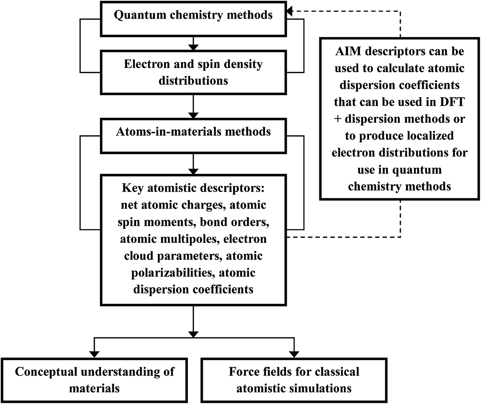 | ||
| Fig. 1 The triple role of AIM methods. AIM methods provide atomistic descriptors that can be used (i) to understand the chemical properties of materials, (ii) to parameterize force fields used in classical atomistic simulations, and (iii) to provide dispersion interactions in some DFT + dispersion methods or to produce localized electron distributions for use in QC methods. | ||
As illustrated in Fig. 2, we envision six pillars of great performance for an AIM method: (a) high chemical accuracy, (b) high force field accuracy, (c) applicability to a broad range of material types, (d) predictably rapid, robust, and unique convergence, (e) computational convenience, and (f) applicability to a broad range of atomistic descriptors. For an AIM method to have high chemical accuracy, it should accurately describe the direction and magnitude of electron and spin transfer among atoms in materials, and the assigned NACs and ASMs should be chemically consistent. For an AIM method to have high force-field accuracy, it should yield force-field parameters that accurately reproduce the electrostatic potential surrounding a material, preferably with good conformational transferability. An AIM method should preferably work well for a broad range of material types including small and large molecules, ions, organometallic complexes, porous and dense solids, solid surfaces, nanostructures, both magnetic and non-magnetic materials, both heavy and light chemical elements, both organic and inorganic materials, both conducting and insulating materials, etc. In order to be used as a default atomic population analysis method (APAM) in QC programs, an AIM method should always converge to a unique solution at a predictably rapid rate. The AIM method should be computationally convenient. Finally, an AIM method should preferably work well for computing a broad range of atomistic descriptors including NACs, atomic multipoles, ASMs, bond orders, atomic polarizabilities, atomic dispersion coefficients, electron cloud parameters, etc.
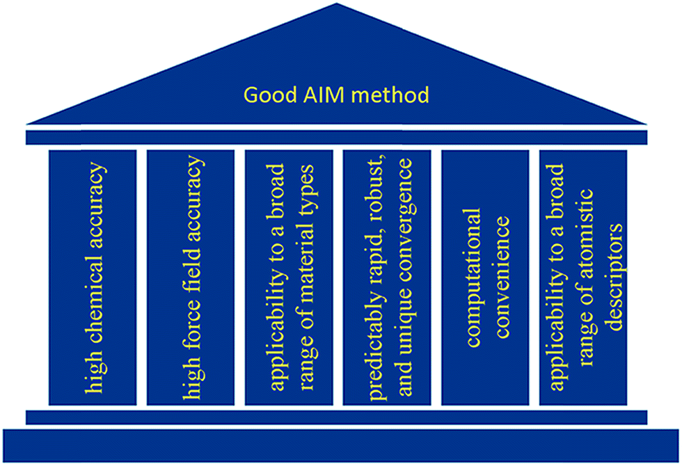 | ||
| Fig. 2 Six pillars of great performance for an AIM method. | ||
To be well-posed, an APAM must be a functional of the electron and spin magnetization density distributions with no explicit dependence on the basis set type or on specific density matrix components or density matrix eigenstates. APAMs lacking a mathematical limit as the basis set is improved towards completeness (e.g., Mulliken13 and Löwdin14) have no physical meaning, because nature corresponds to the complete basis set limit.15 APAMs depending on specific density matrix components or density matrix eigenstates yield inconsistent results for different quantum chemistry methods because near the complete basis set limit the mapping between density matrix and electron density distribution becomes many-to-one.16 Different quantum chemistry methods yielding equivalent electron density distributions and equivalent energies can have vastly different density matrix components and density matrix eigenstates.16
In previous articles of this series, we introduced the DDEC6 AIM method.17,18 In the first article, we described the DDEC6 charge partitioning theory and methodology and showed the assigned NACs and ASMs are chemically consistent.17 We designed the DDEC6 charge partitioning algorithm to meet nine performance goals.17 The DDEC6 method uses the same spin partitioning algorithm as used for earlier DDEC methods.19 In the second article, we tested DDEC6 performance across a broad range of material types and made important comparisons to experimental data.18 In these two prior articles, we demonstrated the DDEC6 method has the first four pillars of high performance: (a) high chemical accuracy, (b) high force field accuracy, (c) applicability to a broad range of material types, and (d) predictably rapid, robust, and unique convergence.17,18
The purpose of the present article is to show how various components of the DDEC6 method can be combined into a fully functional program to achieve pillar (e) computational convenience. Some important aspects of computational convenience include: (1) low computational time, (2) reasonable memory requirements, (3) sufficiently high numerical precision, (4) easy to compute in parallel, (5) easy to prepare the required inputs with minimal manual labor, and (6) easy to read and interpret program outputs.
The sixth pillar of high performance – (f) applicability to a broad range of atomistic descriptors – is partially addressed in the present and previous articles and will be further addressed in future articles. Two previous articles addressed the chemical and force field accuracy of the DDEC6 NACs, atomic dipoles, ASMs, and electron cloud parameters.17,18 A recent article described the theory, methodology, chemical accuracy, and broad applicability of the DDEC6 bond orders.16 The present article focuses on parallel computations of these descriptors, with an emphasis on quantifying computational times, parallelization efficiencies, and memory requirements. Future articles will describe how the DDEC6 method can be extended to compute atomic polarizabilities and dispersion coefficients.
We anticipate this article will be of interest to both users and programmers. Computational materials scientists will benefit from an enhanced understanding of how the DDEC6 method works, its computational performance, and the calculation steps involved. These computational materials scientists are potential users of the DDEC6 method. Second, software developers will benefit from understanding what capabilities the DDEC6 method could bring by being interfaced with their QC packages. The flow diagrams will help both users and programmers understand the calculation sequence.
2. Flow diagrams
2.1 System definition
The system notation we use here is the same as previously published. For completeness, we restate the basic terminology. “Following Manz and Sholl,29 we begin by defining a material as a set of atoms {A} located at positions {![[R with combining right harpoon above (vector)]](https://www.rsc.org/images/entities/i_char_0052_20d1.gif) A}, in a reference unit cell, U. For a nonperiodic system (e.g., a molecule), U is any parallelepiped enclosing the entire electron distribution. The reference unit cell has
A}, in a reference unit cell, U. For a nonperiodic system (e.g., a molecule), U is any parallelepiped enclosing the entire electron distribution. The reference unit cell has ![[small script l]](https://www.rsc.org/images/entities/i_char_e146.gif) 1 = 2 = 3 = 0, and summation over A means summation over all atoms in this unit cell. For a periodic direction, i ranges over all integers with the associated lattice vector
1 = 2 = 3 = 0, and summation over A means summation over all atoms in this unit cell. For a periodic direction, i ranges over all integers with the associated lattice vector ![[v with combining right harpoon above (vector)]](https://www.rsc.org/images/entities/i_char_0076_20d1.gif) i. For a nonperiodic direction, i = 0 and i is the corresponding edge of U. Using this notation, the vector and distance relative to atom A are given by
i. For a nonperiodic direction, i = 0 and i is the corresponding edge of U. Using this notation, the vector and distance relative to atom A are given by
![[r with combining right harpoon above (vector)]](https://www.rsc.org/images/entities/i_char_0072_20d1.gif) A = − 11 − 22 − 33 − A A = − 11 − 22 − 33 − A
| (1) |
A‖.”28 The spherical averages of a scalar function f(A) and vector function ![[g with combining right harpoon above (vector)]](https://www.rsc.org/images/entities/i_char_0067_20d1.gif) (A) about an atom center are defined by
(A) about an atom center are defined by
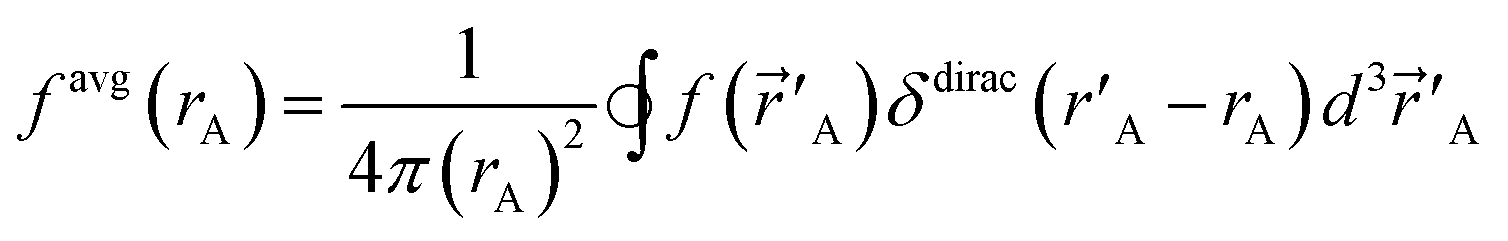 | (2) |
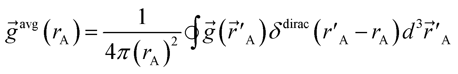 | (3) |
“In this article, we are only interested in studying time-independent states of chemical systems. For such systems, a time-independent electron distribution
ρ() = 〈Ψel|![[small rho, Greek, circumflex]](https://www.rsc.org/images/entities/i_char_e0b7.gif) ()|Ψel〉 ()|Ψel〉
| (4) |
() is the electron density operator”.17
To include enough distinct letters for mathematical symbols, we used characters from the Roman, Greek, and Cyrillic alphabets.
2.2 Master flow diagram
The DDEC6 method was implemented in the CHARGEMOL program using Fortran, a compiled language. The advantage of compiled languages is that they are usually faster than interpreted languages. We used two programming books that explain Fortran commands.20,21 Our program was written using the Fortran 2008 standard with a small number of compiler extensions. Our CHARGEMOL program can be downloaded from http://www.ddec.sourceforge.net.As shown in Fig. 3, the CHARGEMOL program is divided into modules arranged to compute the NACs, ASMs, bond orders, and other properties. The xyz output files containing the NACs, ASMs, r-cubed moments, etc. are readable by the Jmol22,23 visualization program. In addition to the xyz output files, the program also prints a logfile summarizing the calculation sequence including walltime spent for each part of the calculation. The way each block works is described below.
 | ||
| Fig. 3 Flow diagram of the DDEC6 method as implemented in the CHARGEMOL program. The dotted line indicates the path that would be followed if using atom-centered integration grids. | ||
(1) The program checks to make sure the volume per grid point is less than maxpixelvolume.
(2) The program integrates a test function over the integration grid and makes sure the numerically computed value is within a chosen tolerance of the known analytic value.
(3) The program integrates the valence electron density grid to numerically compute the number of valence electrons and adds to this the analytic number of core electrons and the valence occupancy corrections. The program checks to make sure this numerically computed total number of electrons matches the sum of atomic numbers minus the unit cell net charge to within a chosen tolerance.
If these tests are passed, the program proceeds. If not, the program terminates with a message describing the problem with the input files.
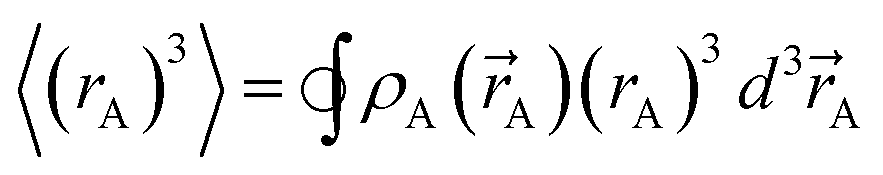
)}, {ρavgA(rA)}, and the NACs {qA}. {ρA(A)} can be regenerated whenever needed from the stored values of {wA(rA)}, {W()}, and {ρ()}. While different charge partitioning algorithms could be employed (e.g., Hirshfeld, ISA, DDEC3, DDEC6), we strongly recommend the DDEC6 algorithm because of its high accuracy, broad applicability, computational efficiency, and convergence robustness.17,18 to ln(ρavgA(rA)) over the range rmin_cloud_penetration ≤ rA ≤ cutoff_radius. For each atom, the electron cloud parameters (
 and
and  ) are printed along with the squared correlation coefficient.
 | (5) |
2.3 Lagrangian series formulation of DDEC6 charge partitioning
Charge partitioning refers to the process of assigning atomic electron distributions {ρA(A)} to the atoms in a material. In all Density Derived Electrostatic and Chemical (DDEC) methods, ρA(A) is simultaneously optimized to resemble its spherical average, ρavgA(rA), and a charge-compensated isolated reference ion of the same element having a similar (but not necessarily equal) charge to the atom in material.17,18,28,29,35 Because the electrostatic potential V() outside a spherical charge distribution is the same as an equivalent point charge, optimizing ρA(A) to resemble ρavgA(rA) makes the DDEC NACs ideally suited for constructing atom-centered point charge models used in force fields for classical atomistic simulations.17,18,28,29 By also optimizing ρA(A) to resemble a charge-compensated isolated reference ion of the same element in a similar charge state, the assigned {ρA(A)} are optimized to resemble real atoms and maximize transferability between similar chemical systems.17,18,28,29 Charge-compensated reference ions are used to account for electrostatic screening by other atoms in the material.17,18,28,29 Conditioning the reference ions to match the material of interest allows the same ratio of spherical averaging to reference ion weighting to be used for all materials.17,28
Table 1 lists the key features of DDEC6 charge partitioning. Each feature was discussed in detail in our prior publication.17 These features are the result of several years of development. Charge-compensated reference ions and spherical averaging were already used in the DDEC/c1 and c2 methods published in 2010.29 Reference ion smoothing, reference ion conditioning, one of the exponential tail constraints, some of the reshaping, and the NvalA ≥ 0 constraint were introduced in the DDEC3 method published in 2012.28 Radial cutoffs and effective all-electron partitioning have been part of the DDEC methods from the beginning.29 The earliest form of stockholder partitioning dates back several decades before the DDEC methods.36 Early forms of stockholder partitioning used reference neutral atoms or uncompensated charged reference ions.36,37 The iterated stockholder atoms (ISA) method used pure spherical averaging without any reference ions to compute the atomic weighting factors.38 A key improvement of the DDEC6 method is that it uses a fixed reference ion charge with a total of seven charge partitioning steps to ensure convergence to a unique solution.17 To more accurately quantify electron transfer, this fixed reference ion charge is optimized to resemble the number of electrons in the volume dominated by each atom.17 The DDEC6 method uses both upper and lower bound constraints on the rate of exponentially decaying buried atom tails to help prevent buried atoms from becoming too diffuse28 or too contracted.17 The DDEC6 method also uses a weighted spherical average, ρwavgA(rA), rather than a simple spherical average to improve the accuracy by which NACs reproduce the electrostatic potential surrounding the material.17
| Feature | Purpose |
|---|---|
| NACs are functional of {ρ()} |
No explicit basis set dependence; consistent results for different SZ values of a spin multiplet |
| Stockholder type partitioning | Atomic densities sum to ρ() at each position |
| Reference ion densities included in atomic weighting factors | Assigned {ρA(A)} resemble real atomic ions |
| Charge compensated reference ions | Accounts for charge compensation and dielectric screening in extended materials |
| Reference ion conditioning | Matches reference ions to the material of interest to improve accuracy; allows a constant proportion of spherical averaging to be used for all materials |
| Fixed reference ion charge | Allows convergence to a unique solution |
| Cutoff radius | Linear scaling computational cost |
| The fixed reference ion charge is optimized to resemble the number of electrons in the volume dominated by each atom | More accurately quantifies electron transfer |
| Upper and lower bound constraints on the rate of exponentially decaying buried atom tails | Exponentially decaying atom tails help to ensure chemically meaningful results; the upper and lower bound constraints help prevent buried atoms from becoming too diffuse or too contracted |
| Adds missing core density (if any) | Effective all-electron partitioning even if the electron distribution was generated using effective core potentials |
| Uses weighted spherical average in atomic weighting factors | Minimizes atomic multipoles to more accurately reproduce V() with NACs |
| Seven charge partitioning steps | Ensures predictably fast and robust convergence |
| Uses smoothed reference ions | Improves optimization landscape curvature by ensuring the reference ions follow expected behavior |
| Constrains NvalA ≥ 0 | Core electrons are assigned to the correct atom |
| Atomic weighting factor reshaping is used when applying the upper and lower bound constraints on the rate of exponentially decaying buried atom tails | Reshaping improves the convergence accuracy by preserving the integral of the atomic weighting factors when applying constraints to prevent atoms from becoming too diffuse or too contracted |
The DDEC6 NACs are functionals of the electron distribution with no explicit dependence on the basis set representation or spin magnetization density. The rational for this is that the NACs should be a compact representation of charge transfer between atoms in materials and also approximately reproduce the electrostatic potential V() surrounding the material. Since charge transfer between atoms in a material cannot occur without a change in ρ() and V() depends only on ρ(), it makes sense for the NACs to be constructed as functionals of ρ().17
Here, we show for the first time that DDEC6 charge partitioning corresponds to solving a series of 14 Lagrangians in order. The DDEC6 method performs vastly better than any of the single Lagrangian charge partitioning methods developed to date.17,18 There are several reasons why such a Lagrangian series performs better than a single Lagrangian for defining the charge partitions. First, to make a Lagrangian convex, it is preferable (maybe even necessary) to keep the reference ion charges fixed. We previously showed the iterative Hirshfeld (IH) and earlier DDEC methods that iteratively update the reference ion charges to self-consistency are non-convex and converge non-uniquely in some materials.17 We have not been able to prove convexness for a single iteratively solved Lagrangian that combines reference ion updating with weighted spherical averaging with reshaping. The need to update the reference ion charges to approximately match the AIM charges thus needs a Lagrangian series. We prove the DDEC6 optimization landscape is convex by showing each Lagrangian in this series is convex.
Second, separating charge partitioning from reshaping Lagrangians requires only one charge cycle per charge partitioning Lagrangian (except when the NA − NcoreA ≥ 0 constraint is binding), while a Lagrangian that performs both charge partitioning and reshaping must be solved through an iterative algorithm that requires several charge cycles over all grid points to reach self-consistency. Consequently, a charge partitioning Lagrangian series has faster, more computationally efficient, predictable, and robust convergence than a single charge partitioning Lagrangian incorporating reshaping that is self-consistently iterated to convergence.
However, having too many Lagrangians in the charge partitioning Lagrangian series is detrimental. The reason has to do with spontaneous symmetry breaking. Consider a system containing two symmetry equivalent atoms. A small error ε in the input density grid may cause the minimum of a single Lagrangian  in this series to be symmetry broken by some amount
  where
where  describes the ratio of the output to the input symmetry breaking. The input to the second Lagrangian in the series will thus be symmetry broken by an amount
  and its minimum will be symmetry broken by an amount
 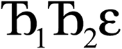 . After
  Lagrangians in the series, the spontaneous symmetry breaking (SSB) equals
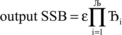 | (6) |
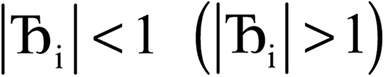 , the magnitude of the output SSB will be smaller (larger) than the input SSB ε. Even if
  , the output SSB can be contained by keeping
  and ε small. For
 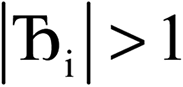 and
and  , the output SSB cannot be contained and runaway charges will result.
Therefore, optimal performance will be obtained by using a charge partitioning Lagrangian series containing more than one but not too many Lagrangians. What is an appropriate number of Lagrangians in this series? Fourteen. These are defined as follows:
 | (7) |
 | (8) |
 | (9) |
 | (10) |
| NvalA = NA − NcoreA ≥ 0 | (11) |
Table 2 summarizes the organization of these 14 Lagrangians into seven charge partitioning steps. Section S1 of ESI† contains the detailed mathematical forms of these 14 Lagrangians. The computational algorithm for these seven DDEC6 charge partitioning steps was described in detail in our previous article.17 A flow diagram for DDEC6 charge partitioning was presented in Fig. S2 of the ESI of our previous article.17 Fig. S1 and S3 of that article presented flow diagrams for reshaping the conditioned reference ion density and to prevent wA(rA) from becoming too diffuse, respectively.17 As noted in our earlier publication, the Hirshfeld NACs, atomic dipoles and quadrupoles and the CM5 NACs were readily computed and printed during the first charge partitioning step.17
| Charge partitioning step | Stockholder Lagrangian | Enforce NA − NcoreA ≥ 0? | Reshaping Lagrangians |
|---|---|---|---|
| 1 |  |
N | None |
| 2 |  |
N | None |
| 3 |  |
N |  |
| 4 |  |
N |  |
| 5 |  |
Y |  |
| 6 |  |
Y |  |
| 7 |  |
Y | None |
We now briefly summarize how these seven DDEC6 charge partitioning steps were efficiently parallelized. Loops over atoms and grid points were parallelized over the grid point index. As demonstrated in Section 4.2 below, this provided efficient parallelization even for systems containing only one atom in the unit cell. Two pure subroutines were created to perform reshaping. A pure subroutine is one that can be readily parallelized over, because it has no side effects on data outside the procedure. The first of these subroutines performed reshaping of the conditioned reference ion densities. The second of these subroutines performed reshaping to prevent wA(rA) from becoming too diffuse or too contracted. These subroutines were parallelized over atoms, such that each processor called the reshaping subroutine to act on a different atom. For convenience, a Fortran module containing these reshaping subroutines is provided in the ESI.†
2.4 Spin partitioning details
In contrast to DDEC6 charge partitioning that requires a Lagrangian series, DDEC spin partitioning requires minimizing only a single Lagrangian. The DDEC spin partitioning Lagrangian was introduced by Manz and Sholl19 and is summarized in Section S2.1 of ESI.† Fig. S1 of ESI† shows a flow diagram for spin partitioning. Why does spin partitioning use a single iterative Lagrangian while charge partitioning uses a Lagrangian series? The most fundamental difference is that the reference ion state must be updated during the early stages of charge partitioning, while the proportional spin partition (which acts as a reference state for spin partitioning) does not require any updates. Convexness is guaranteed only if the reference ion updating in DDEC6 charge partitioning is performed in a fixed finite sequence (i.e., Lagrangian series) rather than iterated to self-consistency. Also, convexness is guaranteed only if the weighted spherical averaging in DDEC6 charge partitioning is performed in a fixed finite sequence (i.e., Lagrangian series) rather than iterated to self-consistency. Simple spherical averaging can be incorporated into a convex Lagrangian iterated to self-consistency. DDEC spin partitioning incorporates a simple spherical averaging of![[m with combining right harpoon above (vector)]](https://www.rsc.org/images/entities/i_char_006d_20d1.gif) A(A).
A(A).
The major features of DDEC spin partitioning are summarized in Table 3.19 First, the assigned {A(A)} sum to () at each position . This also ensures the sum of ASMs will always yield back the total spin magnetic moment of the unit cell. Second, both proportional spin partitioning and spherical averaging are included in the spin partitioning optimization functional to ensure chemically reasonable results and to accurately reproduce the magnetic field due to spin, ![[B with combining right harpoon above (vector)]](https://www.rsc.org/images/entities/i_char_0042_20d1.gif) spin(), around the material.19 Constraining the optimization functional so the atomic spin magnetization density is less than or equal to the atomic electron density ensures the resulting ASMs will be chemically meaningful.19 Spin magnetization density is represented as a vector to make the approach applicable to both collinear and non-collinear magnetism.19 In the case of collinear magnetism, efficiency is maximized by only computing and storing the non-zero component.19 Similar to the NACs calculation, ASMs are computed using a cutoff radius to ensure linear scaling computational cost with increasing system size.19
spin(), around the material.19 Constraining the optimization functional so the atomic spin magnetization density is less than or equal to the atomic electron density ensures the resulting ASMs will be chemically meaningful.19 Spin magnetization density is represented as a vector to make the approach applicable to both collinear and non-collinear magnetism.19 In the case of collinear magnetism, efficiency is maximized by only computing and storing the non-zero component.19 Similar to the NACs calculation, ASMs are computed using a cutoff radius to ensure linear scaling computational cost with increasing system size.19
| Feature | Purpose |
|---|---|
Constraint ensures 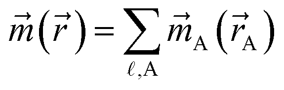 |
Spin magnetization divided exactly amongst atoms |
| Proportional spin partitioning included in optimization functional | Helps to ensure chemically reasonable results |
| Spherical averaging included in optimization functional | ASMs more accurately reproduce spin() around material |
| Constraint ensures mA(A) ≤ ρA(A) |
Ensures chemical feasibility |
| Spin magnetization density represented as a vector | Works for collinear and non-collinear magnetism |
| Cutoff radius | Linear scaling computational cost |
| Convex optimization functional with exponentially fast convergence | Predictably unique and rapid convergence |
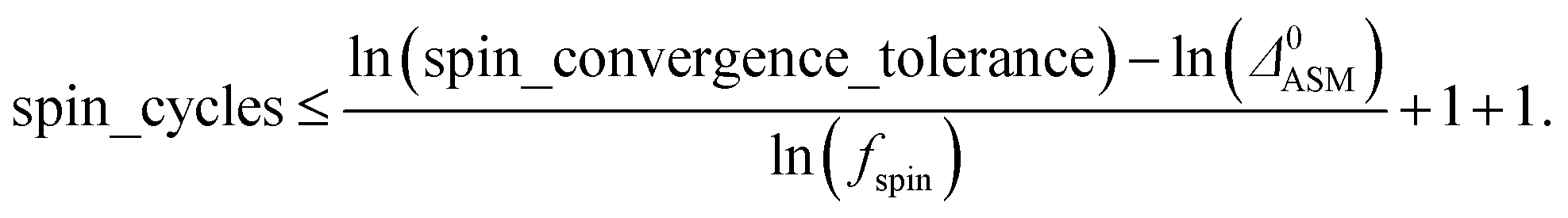
A predictably fast and unique convergence is achieved by using a provably convex19 optimization functional with exponentially fast17 convergence. As explained in Section S3.2.4 of our previous article,17 the max_ASM_change for spin cycle j + 1 is approximately
 | (12) |
| max_ASM_change|j+1 ≈ fspinmax_ASM_change|j | (13) |
 | (14) |
 | (15) |
2.5 Bond order analysis
A new method to compute bond orders was developed by Manz16 and is implemented in the DDEC6 method. Key advantages of this method are summarized in Table 4. First, the method uses appropriate cutoffs to achieve an efficient linearly scaling computational cost.16 Second, exchange interactions are formulated in vector form to achieve a unified description of no magnetism, collinear magnetism, and non-collinear magnetism.16 To save memory and computational time, only the non-zero exchange components are computed and stored.16 Theoretical lower (1×) and upper (2×) bounds on the bond-order-to-contact-exchange ratio improve the method's accuracy.16 Bond orders are computed as functionals of {(ρ(),())} to ensure approximately consistent results across various exchange–correlation theories, basis sets, and SZ values of a spin multiplet.16
| Feature | Purpose |
|---|---|
| Computes atom–atom overlaps to determine which bond orders are negligible and uses cutoff radii | Linearly scaling computational cost |
| Exchange interactions formulated in vector form with allocation of exact number of exchange components | Applies to systems with no magnetism, collinear magnetism, and non-collinear magnetism |
| Lower and upper bounds on the bond order | Improves accuracy |
| Bond orders are computed as functionals of {(ρ(),())} |
Ensures consistent results across various exchange–correlation theories and basis sets |
| Based on DDEC6 ρavgA(rA) and avgA(rA) |
Satisfies confluence of atomic exchange propensities |
There are several specific features of DDEC6 partitioning that make it exceptionally well-suited for computing bond orders. First, the DDEC {A(A)} are simultaneously optimized to resemble proportional spin partitioning and {avgA(rA)}; this is crucial to satisfy the confluence of atomic exchange propensities.16 Second, the DDEC6 charge partitions are simultaneously optimized such that: (a) ρA(A) resembles ρavgA(rA), (b) NA resembles the number of electrons in the region of space dominated by atom A, (c) wA(rA) and ρA(A) resemble a reference ion of the same element in a similar (but not necessarily identical) charge state, and (d) the buried tails of atoms decay exponentially with increasing rA at a rate that is neither too fast nor too slow. Property (a) is also needed to satisfy the confluence of atomic exchange propensities.16 Properties (b), (c), and (d) help to ensure chemically correct atoms-in-materials partitioning.
The first step in bond order analysis is to set the number of exchange components. Spin unpolarized calculations have only one exchange component: the electron density ρ(). Collinear magnetism calculations have two exchange components: the electron density and the spin density. Non-collinear magnetism calculations have four exchange components: the electron density and x, y, z components of the spin magnetization density vector, (). The arrays and computational routines in bond order analysis are designed such that exactly the corresponding number of exchange components are allocated in memory and computed.
The second step is to prepare the density grids for bond order analysis. Bond order computation requires including the exchange of all electrons (i.e., both core and valence electrons) to accurately model the exchange hole. During the charge and spin partitioning, we used a valence-core separation scheme that includes occupancy corrections to yield accurate integrations.17,18,28 Since electron exchange is non-linear in ρ(), it is not straightforward to perform a valence-core separation for the exchange hole. Therefore, it is necessary to modify the total electron density grid to directly include the occupancy correction for each atom so that direct integration of the atom-partitioned total electron density grid yields the correct DDEC6 atomic populations without requiring a core-valence separation. Since the occupancy correction corrects for the integration error in the valence electron cusp near each atomic nucleus, we restricted the total electron density grid correction to those pixels near each atomic nucleus (i.e., a 5 × 5 × 5 block of grid points around each nucleus). This process does not change the DDEC6 NACs.
With some differences, this numerical correction of the total electron density grid is analogous to the core electron grid correction described in the ESI of our previous publication.17 Table 5 summarizes the differences between the core electron grid correction and the total electron density grid correction. A key difference is that {wcoreA(rA)} is updated during core electron grid correction, while {wDDEC6A(rA)} is not altered in any way during the total electron density grid correction. Section S4 of ESI† contains a detailed description and flow diagram (Fig. S2†) of the total electron density grid correction. The implementation we used performed core electron grid correction during the core electron partitioning and total electron density grid correction at the beginning of bond order analysis. The corrected total electron density, ρ(), and corrected spherical average densities, {ρavgA(rA)},are then used throughout the bond order analysis to achieve results.
| Aspect | Core electron grid correction | Total electron grid correction |
|---|---|---|
| Electron density | Core | Total (core + valence) |
| When correction formed | During core partitioning | At start of bond order analysis |
| Target atomic populations | NcoreA | NDDEC6A |
| Grid points corrected | All | 5 × 5 × 5 block around each nucleus |
| Atomic weighting factors | wcoreA(rA) | wDDEC6A(rA) |
Fig. 4 shows a flow diagram for bond order analysis. As stated above, the first step sets the number of exchange components, and the second step prepares the density grids. The third step computes the local atomic exchange vectors. The fourth step identifies all translation symmetry unique atom pairs that could have a bond order equal to or greater than the bond order print threshold (e.g., 0.001). These are listed in the bond pair matrix. The fifth step computes various integrated terms for each atom pair in the bond pair matrix: contact exchanges, overlap populations, etc. The sixth step uses these integrated terms to compute the bond orders and SBOs. The seventh step prints these to output files.
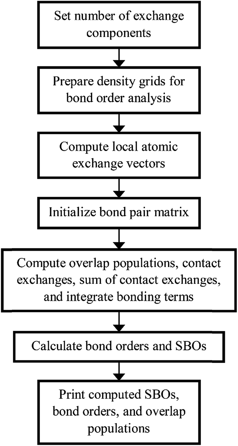 | ||
| Fig. 4 Flow diagram of DDEC6 bond order analysis. | ||
We parallelized the second, third, and fifth steps over grid points. Alternatively, one could parallelize these steps over atoms (for quantities involving individual atoms) or atom pairs (for quantities involving atom pairs).
Additional bond order analysis details are summarized in Section S3 of ESI.† Eqn (S80)† quantifies the spin polarization of each bond by computing a chemical descriptor that varies from 0 (completely paired electrons) to 1 (all electrons of same spin) with intermediate values indicating a partially spin-polarized bond. Equations for computing bond order (eqn (S81)†), SBO (eqn (S87)†), contact exchange (eqn (S75)†), SCE (eqn (S79)†), and overlap population (eqn (S76)†) are given. Theory behind these equations was presented in an earlier article.16
3. Parallelization strategy and memory management
3.1 Overall strategy
Today's high performance computing clusters are usually comprised of several compute nodes in which each node has several processors sharing a random access memory (RAM). Processors on a single compute node are cache coherent, while processors from different compute nodes are not cache coherent. Two main schemes are available to parallelize a program: (a) using shared memory (for example, open multi-processing (OpenMP)) to parallelize across cache-coherent processors on a single compute node and (b) using distributed memory (for example, message passing interface (MPI)) to parallelize across non-cache-coherent processors (e.g., those from different compute nodes). The limitation of using just OpenMP as a parallelization scheme is that the program is restricted to parallelization over processors and memory available on a single shared-memory node.39,40 MPI has the advantage that it can make use of memory and processors from multiple compute nodes.The parallelization scheme chosen for CHARGEMOL was shared memory because it is easy to create a shared memory program if the serial program already exists. The only thing needed is to add OpenMP directives that will be processed by the compiler.39,40 Another advantage is that the user does not have to compile extra libraries to get the OpenMP parallelization. If the compiler does not support OpenMP, the program will be compiled in the serial mode and the parallel directives will be ignored. Examples of OpenMP directives are shown in Fig. 5. We used two programming guides that explain OpenMP directives.39,40
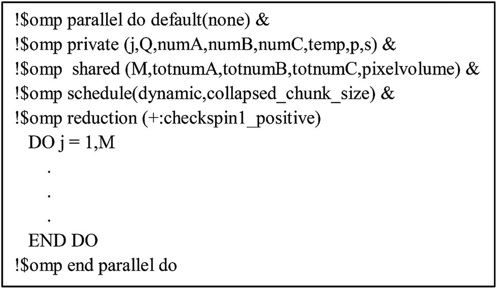 | ||
| Fig. 5 Example OpenMP directives that create threads and divide the work. The loop is parallelized over j. | ||
We used OpenMP because it is easier to program, but many of our suggestions for efficient parallelization would also apply to strategy (b) utilizing a MPI. The MPI parallelization strategy is often preferred by QC codes that perform calculations across multiple compute nodes. Lee et al.41 incorporated DDEC3 into ONETEP42 and used MPI to parallelize it across nodes to study large biomolecules and other materials containing thousands of atoms. The distributed memory strategy of Lee et al.41 could be used to parallelize the DDEC6 method across multiple compute nodes. It is also possible to combine MPI and OpenMP such that parallelization within a node is handled by OpenMP and parallelization across nodes is handled by MPI,43 but we have not yet implemented any of the DDEC methods using hybrid MPI-OpenMP parallelism.
In order to create an efficient shared memory parallel program, the elements listed in Fig. 6 had to be achieved: (a) set big matrices as shared variables, (b) order the loop indices, (c) parallelize over grid points, bond pairs (i.e., pairs of atoms having non-negligible bond order), or atoms depending on the best option for a particular case, (d) minimize the number of CRITICAL directives, and (e) minimize thread creation.
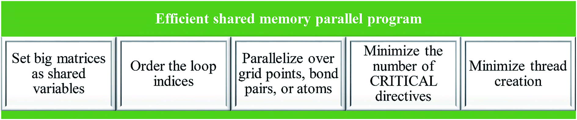 | ||
| Fig. 6 Elements for achieving an efficient shared memory parallelization of the DDEC6 method. | ||
The big matrix elements run over all grid points in the unit cell. That is, they have a form my_array(a, b, c) where the value of (a, b, c) determines a particular grid point in the unit cell. In Fortran, the first index is the fast changing index that references adjacent memory values. Thus, my_array(1, 200, 300) is stored adjacent to my_array(2, 200, 300).
Obviously, computational loops that run over the largest number of elements are the most important to parallelize. These include: (a) loops over grid points in the unit cell, (b) loops over atoms and spatial positions {A}, (c) loops over bond pairs and relevant spatial positions for each bond pair, and (d) for Gaussian basis set coefficients inputs there are loops that run over relevant spatial positions for each non-negligible pair of Gaussian basis functions. Loops of type (a) are parallelized over grid points. Loops of type (b) can be parallelized over either (bi) atoms or (bii) spatial positions for an atom. Here, we have used strategy (bii), while an earlier paper on MPI parallelization of the DDEC3 method used strategy (bi).41 Loops of type (c) can be parallelized either over (ci) relevant spatial positions for a bond pair or (cii) bond pairs. We tested both of these strategies and found they both work well. Results in this paper are for strategy (ci). For loops of type (d), we parallelized over blocks of non-negligible Gaussian basis function pairs, but this requires using ATOMIC directives when writing to the electron and spin density grids (as described in the ESI of one of our previous articles,17 pairs of Gaussian basis functions within a single block share the same exponent and center, while different blocks have different exponents or different centers).
3.2 Minimizing memory requirements
Each variable in a parallel region of a code must be declared as shared or private.39,40 Shared variables have a common value accessed by all the threads, while private variables have a different value for each thread. Private variables will not retain their value when the threads are destroyed. Temporary variables, index numbers, loop iteration indices, and other local variables were set as private. The big arrays in the program (i.e., the ones that run over grid points) take up the most memory. Big arrays are treated as shared variables. Whenever a big array was no longer needed, it was deallocated to free up some memory.The big arrays are listed in Fig. S3.† Each row stands for a big array and each column stands for a module in the program. Not all of the program's modules are listed, only the ones where big arrays are allocated or deallocated. The modules are listed in order with earlier modules listed to the left. Fig. S3† shows in which module each big array is allocated and deallocated. The continuous colored line represents when each big array exists. Green blocks are used by all of the systems. Yellow blocks are used only by systems with collinear magnetism. Red blocks are used only by systems with non-collinear magnetism. The height of a cell is proportional to the amount of memory the big array requires. For example, if the cell has a height of 3 small cells the big array requires triple the memory of a small cell, because that big array stores information for three vector components at each grid point.
Fig. 7 shows the number of values that must be stored for each grid point at the same time when the program is in certain modules. Earlier modules are listed towards the top and later modules towards the bottom. Some modules will be skipped depending on the calculation type: (i) only one of the read density grids or prepare density grids from basis set coefficients modules will be run depending on whether the density grids are read from files or computed from the basis set coefficients, respectively, and (ii) the spin moments iterator will be run only if the system is magnetic. The total memory required to complete the DDEC analysis is proportional to the length of the cells in Fig. 7. As mentioned above, big matrices that will not be used anymore were deallocated. If the system is non-magnetic, the largest memory requirement will be in the valence iterator or reading of input density grids. Non-magnetic systems use only green cells and the highest memory requires storing 6 values over the grid points (i.e., nlarge = 6). For magnetic materials, the computation of ASMs requires the largest memory. For systems with collinear magnetism, the required memory is proportional to the height of green and yellow cells, and there is a maximum storage requirement of 8 values over the grid points (i.e., nlarge = 8). For systems with non-collinear magnetism, the required memory is proportional to the height of green, yellow, and red cells, and there is a maximum storage requirement of 20 values over the grid points (i.e., nlarge = 20). Overall, DDEC6 analysis required the same amount of memory as DDEC3 analysis.
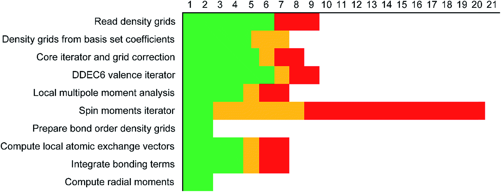 | ||
| Fig. 7 Illustration of the maximum amount of big arrays that exist at the same time per module. The green bars are for all systems. The yellow bars indicate the additional memory for systems with collinear magnetism. The memory required for non-collinear magnetism is the sum of the green, yellow, and red bars. | ||
Based on Fig. 7, the total RAM (in megabytes) required to run the program is estimated using the formulas
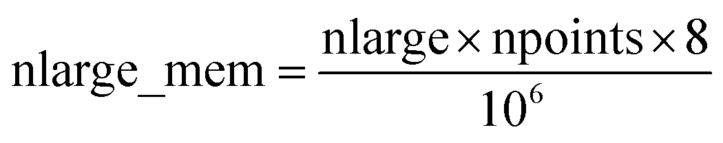 | (16) |
 | (17) |
Table 6 summarizes the minimum memory requirements for running a diverse set of materials on serial and 8 parallel processors. This test set spanned from one atom per unit cell (i.e., Ni metal fcc crystal) to 733 atoms per unit cell (i.e., B-DNA decamer). These systems spanned different kinds of magnetism: (a) non-magnetic (i.e., B-DNA decamer and ozone singlet), (b) collinear magnetism (i.e., Mn12-acetate single molecule magnet, Ni metal, and ozone triplet), and (c) non-collinear magnetism (i.e., Fe4O12N4C40H52 single molecule magnet). Different types of basis sets (i.e., planewave and Gaussian) are contained in this test set. As demonstrated by the results in Table 6, the total RAM requirements were nearly identical for serial and 8 parallel processors. This indicates an efficient memory management for which adding parallel processors does not significantly change the total memory requirements. The last column in Table 6 lists the total memory requirements predicted by eqn (17). This prediction contains a margin of safety such that the predicted total memory should be large enough to accommodate the calculation.
| System | Atoms in unit cell | Basis set type | Magnetism | Serial | 8 processors | Predicted (eqn (17)) |
|---|---|---|---|---|---|---|
| B-DNA decamer | 733 | Planewave | None | 4500 | 4500 | 4650 |
| Fe4O12N4C40H52 SMM | 112 | Planewave | Non-collinear | 2500 | 2500 | 2910 |
| Mn12-acetate SMM | 148 | Planewave | Collinear | 480 | 490 | 828 |
| Mn12-acetate SMM | 148 | Gaussian | Collinear | 2900 | 2900 | 3294 |
| Ni metal | 1 | Planewave | Collinear | 5 | 6 | 8 |
| Ozone singlet (CCSD) | 3 | Gaussian | None | 250 | 260 | 362 |
| Ozone triplet (CCSD) | 3 | Gaussian | Collinear | 340 | 340 | 449 |
3.3 Minimizing false sharing
Cache is an intermediary between the processors and main memory.40 Cache stores temporary information so the processor does not have to travel back and forth to the main memory. However, cache is small and sometimes it cannot store all the information the program needs. In order to maximize cache efficiency, the number of fetches to main memory the processor makes should be kept to a minimum. In modern computer architectures, there are usually multiple layers of cache.The precise size of a cache line depends on the implementation; 64 bytes is common, which means a cache line can store eight double precision (64 bit) real numbers. To maximize performance, a single thread of the parallel program should use all of these numbers before requiring the next fetch. Therefore, a single thread should consecutively run over adjacent values of the inner index, and threads should be parallelized over one of the outer indices. This means that a should be the inner (fast) loop and c should be the outer (slow) loop when assigning values to my_array(a, b, c) using a Fortran Do loop. The correct organization of the loops in the program is represented in Fig. 8. When using the correct loop order, each thread will update several consecutive array values before requiring a fetch from main memory (or outer cache) to inner cache of the next several array values. Since the different parallel threads are working on array elements corresponding to different cache lines, each thread will not slow down the performance of the other threads.
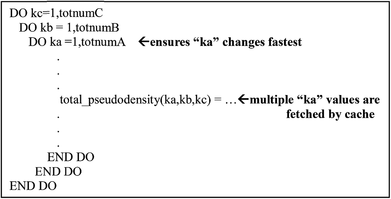 | ||
| Fig. 8 Example of the arrangement of loop and matrix indices to maximize cache efficiency. This structure was used throughout the program. | ||
Using an incorrect loop order can cause false sharing.40 In false sharing, parallel threads write to different matrix elements on the same cache line. Because the first processor invalidates the cache line upon writing, the second processor must wait for the cache line to reload before writing its value, and the third processor must wait for another reload before it writes. This makes each cache line load several times instead of once. This also means that the next array element required by the first processor may not yet be in inner cache, which would require a new fetch from main memory (or outer cache) to inner cache for each newly required array element. The result is a lot of wasted motions.
We tested the efficiency of parallelizing over the number of atoms on two different types of arrays. Let us define one array where the first index (corresponding to the radial shell) varies according to the distance from the atomic nucleus and a second index depends on the atom number: my_array_1(radial_shell, atom_number). Let us define another array that only depends on the atom number: my_array_2(atom_number). In the first case, loops were set so radial_shell was the fast index. We tested the efficiency of parallelizing loops in the DDEC6_valence_iterator module that iterate over the number of atoms. The system tested was an ice crystal with 6144 atoms. We used 16 processors. Because of false sharing where different processors try to update adjacent array values in the same cache line, a parallel loop containing variables of the type my_array_2 took almost three times longer when parallelized than in the serial mode. In contrast, the parallelization efficiency was 98% when the loop containing variables of the type my_array_1 was parallelized over atom_number. False sharing is minimized for this kind of loop because radial_shell is the fast index and different processors work on different values of the slow index (atom_number). This is why we parallelized over the number of atoms some loops that contained variables of the type my_array_1 but not my_array_2.
To test cache performance, we generated a code with the correct (“fast code”) and incorrect (“slow code”) order of loop indices when writing updated values to the big arrays. Computational tests for the Mn12-acetate single molecule magnet using the PBE/planewave densities are shown in Table 7. Three runs were performed and the average and standard deviation are reported. The slow code took longer to run than the fast code. On 8 and 16 processors, spin partitioning took almost twice as long using the slow code compared to the fast code, and overall DDEC6 analysis took ∼50% longer. Examining the code, spin partitioning exhibited the worst slowdown, because it has the highest fraction of loops over grid points that write updated values to the big arrays. It is amazing that the overall performance of the slow code was not worse. This clearly indicates the Xeon multi-processor unit we used is highly efficient. In particular, it has out-of-order execution that allows commands to be executed out of order to mitigate effects of waiting for data to be fetched from main memory to cache. While the processor is waiting for data to be fetched, it will execute another command for which the input data is available.
| Number of processors | ||||||
|---|---|---|---|---|---|---|
| Serial | 1 | 2 | 4 | 8 | 16 | |
| Setting up density grids | 1.070 ± 0.022 | 1.069 ± 0.005 | 1.105 ± 0.025 | 1.103 ± 0.008 | 1.095 ± 0.002 | 1.065 ± 0.013 |
| Core electron partitioning | 1.327 ± 0.106 | 1.215 ± 0.025 | 1.388 ± 0.012 | 1.536 ± 0.001 | 1.758 ± 0.028 | 1.801 ± 0.008 |
| Charge partitioning | 1.218 ± 0.052 | 1.181 ± 0.002 | 1.292 ± 0.007 | 1.306 ± 0.101 | 1.558 ± 0.090 | 1.552 ± 0.087 |
| Spin partitioning | 1.395 ± 0.032 | 1.361 ± 0.009 | 1.513 ± 0.014 | 1.658 ± 0.012 | 1.900 ± 0.014 | 1.988 ± 0.020 |
| Bond order analysis | 1.144 ± 0.042 | 1.101 ± 0.007 | 1.101 ± 0.007 | 1.157 ± 0.012 | 1.206 ± 0.009 | 1.177 ± 0.084 |
| Total time | 1.267 ± 0.056 | 1.211 ± 0.008 | 1.211 ± 0.008 | 1.392 ± 0.019 | 1.540 ± 0.020 | 1.519 ± 0.036 |
3.4 Reductions
Several OpenMP directives are designed to prevent racing conditions.39,40 A racing condition occurs if two processors try to write to the same memory location at the same time. The ATOMIC directive was set when the value of a variable had to be updated in main memory by different processors. The REDUCTION directive was used to parallelize sums, subtractions, finding a maximum or a minimum value, etc. The CRITICAL directive allows only one thread at a time to perform a set of code operations. ATOMIC, CRITICAL, and REDUCTION were tested to see which one was the least computationally expensive. REDUCTION was the least time consuming. These directives were kept to a minimum to avoid overhead cost. To avoid memory requirements increasing with the number of parallel processors, no REDUCTION was used over big arrays.Fig. 9 shows two different placements of the REDUCTION clause. We tested the parallelization efficiency on 16 processors. The system studied was an ice crystal with 6144 atoms in the unit cell. When REDUCTION was set like the top panel of Fig. 9, 403 seconds were needed to complete the parallel section. In this case, the REDUCTION clause is performed natoms times. Because an array containing a dimension of length natoms must be reduced over natoms times, the time to complete the loop scales poorly as the number of atoms increases. When REDUCTION was set as in the bottom panel of Fig. 9, only 79 seconds were needed to complete the parallel section. In this case, the REDUCTION clause is performed just once. Therefore, whenever possible, we set the REDUCTION clauses as in the bottom panel of Fig. 9.
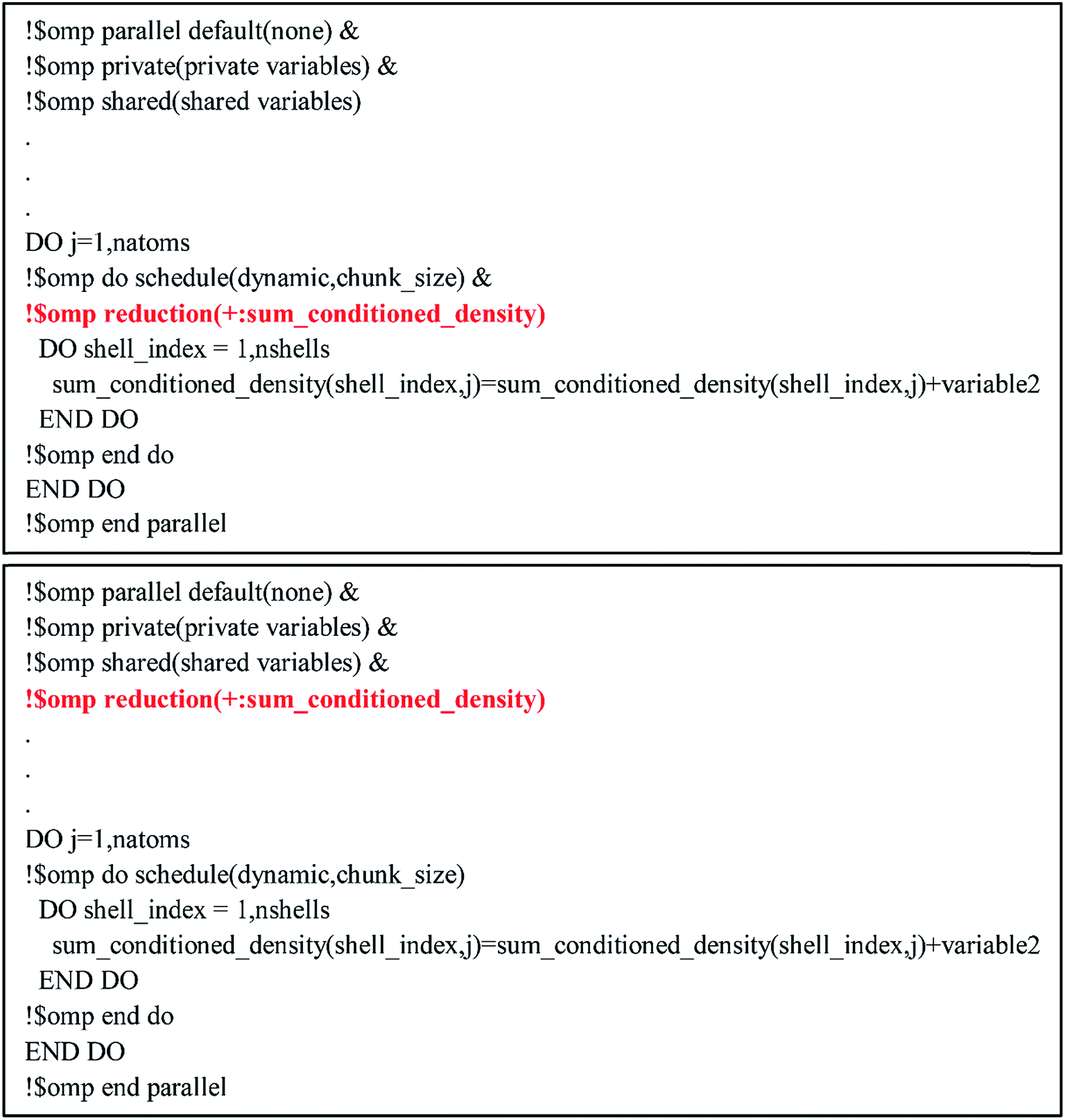 | ||
| Fig. 9 Example of parallelization codes using (top) inefficient placement of REDUCTION statement and (bottom) efficient placement of REDUCTION statement. The bottom configuration is preferred because the REDUCTION clause is executed just once, while the top code executes the REDUCTION clause natoms times. | ||
3.5 Scheduling and thread binding
The OpenMP clause SCHEDULE was specified to control the way the work was distributed among the threads.39,40 The keyword STATIC was used when the processors would perform the same number of operations in each loop iteration, ensuring balance of work among the processors. DYNAMIC was set when the number of operations per loop iteration could vary. In DYNAMIC scheduling, the next loop iteration is assigned to the first free processor. DYNAMIC scheduling achieves better load balancing but has higher overhead than STATIC scheduling.39,40A thread in OpenMP can be bound to a particular processor or it can be allowed to switch between processors. This is controlled through the environmental variable OMP_PROC_BIND. When this variable is set to TRUE, a thread does not switch between processors. If the variable is set to FALSE, a thread can switch between processors. We ran tests on the Mn12-acetate SMM system to test whether the value of OMP_PROC_BIND affects the calculation time. Table 8 shows the time per atom to perform the DDEC6 calculation. Setting OMP_PROC_BIND to TRUE or FALSE gave nearly identical times to complete the calculation. Since the difference was not significant and since not specifying a value for OMP_PROC_BIND gives similar results, we did not specify the OMP_PROC_BIND variable for any of the other calculations in this work.
| OMP_PROC_BIND | ||||
|---|---|---|---|---|
| 16 threads on 16 processors | 32 threads not specified | |||
| True | False | Not specified | ||
| Setting up density grids | 0.1381 ± 0.0003 | 0.1389 ± 0.0008 | 0.1459 ± 0.0065 | 0.1376 ± 0.0002 |
| Core electron partitioning | 0.1946 ± 0.0001 | 0.1943 ± 0.0000 | 0.1945 ± 0.0000 | 0.1873 ± 0.0002 |
| Charge partitioning | 0.1368 ± 0.0053 | 0.1388 ± 0.0101 | 0.1364 ± 0.0057 | 0.1359 ± 0.0040 |
| Spin partitioning | 0.1828 ± 0.0014 | 0.1816 ± 0.0004 | 0.1858 ± 0.0035 | 0.1905 ± 0.0010 |
| Bond order analysis | 0.1906 ± 0.0003 | 0.1908 ± 0.0010 | 0.2129 ± 0.0374 | 0.2505 ± 0.0028 |
| Total time | 0.8705 ± 0.0040 | 0.8719 ± 0.0096 | 0.9033 ± 0.0292 | 0.9345 ± 0.0059 |
As a further test of thread configurations, we also tested two threads per processor (i.e., 32 OpenMP threads on 16 processors). As shown in Table 8, most of the modules were completed in the same amount of time as using one thread per processor (i.e., 16 OpenMP threads on 16 processors), except for the bond order analysis where the time for two threads per processor increased the required times ∼20% compared to using one thread per processor. For this reason, we used one thread per processor for all of the other calculations in this work.
Because of the almost negligibly small standard deviations in the computational times, except where otherwise specified throughout the remainder of this article we performed only one run for each computational test rather than running replicates.
4. Results and discussion
4.1 Overview of systems studied
Table 9 summarizes systems studied in the computational timing and memory tests. These systems were chosen to represent a wide range of materials (column 1), number of atoms per unit cell (column 2), exchange–correlation (XC) theories (column 3), and basis sets (column 4). VASP24–27 and GAUSSIAN 09 (ref. 44) software packages were used to generate electron distributions for the planewave and Gaussian basis set calculations, respectively. These materials were selected to contain a wide range of different chemical elements. The fifth column in Table 9 lists references describing details of electron density calculations and geometry. Because required computational times and total memory requirements depend strongly on the total number of grid points, the last three columns in Table 9 list the total number of grid points, the unit cell volume, and the volume per grid point. For non-periodic materials, the unit cell volume was left blank. VASP calculations of molecules or clusters (e.g., water dimer, X@C60 endohedral complexes, Fe4O12N4C40H52 non-collinear single molecule magnet (SMM)) used a vacuum space between atoms in neighboring images. For all GAUSSIAN 09 calculations (e.g., Mn12-acetate SMM with LANL2DZ basis set and all ozone systems), “density = current output = wfx” was specified to prompt GAUSSIAN 09 to print the wfx file that is subsequently analyzed by the CHARGEMOL program.| System | Number atoms | XC theory | Basis set | Reference | Total number of grid points | Unit cell volume (bohr3) | Volume per grid point (bohr3) |
|---|---|---|---|---|---|---|---|
| a Several additional sets of grid points were also considered for this material as described in Sections 4.5 and 4.6.b Additional calculations performed for the same molecule with CASSCF/AUG-cc-pVTZ, CCSD/AUG-cc-pVTZ, PW91/6-311+G*, and SAC-CI/AUG-cc-pVTZ levels of theory with identical total number of grid points and volume per grid point.c Additional calculations performed for the same molecule with CCSD/AUG-cc-pVTZ and PW91/6-311+G* levels of theory with identical total number of grid points and volume per grid point.d Endohedral complexes with X = Am+1, Cs, Eu+1, Li, N, and Xe. | |||||||
| Ni metal | 1 | PBE | Planewave | This work | 32![[thin space (1/6-em)]](https://www.rsc.org/images/entities/char_2009.gif) 768 768 |
73.4 | 0.0022 |
| Ice crystals | 12 | PBE | Planewave | 16 | 345600 |
874.2 | 0.0025 |
| 96 | 2764800 |
6993.7 | 0.0025 | ||||
| 324 | 9331200a |
23603.9 |
0.0025a | ||||
| 768 | 22118400 |
55949.9 |
0.0025 | ||||
| 1500 | 43200000 |
109277.1 | 0.0025 | ||||
| 2592 | 74649600 |
188830.9 | 0.0025 | ||||
| 4116 | 118540800 |
299856.4 | 0.0025 | ||||
| 6144 | 176947200 |
447599.1 | 0.0025 | ||||
| 8748 | 251942400 |
637304.2 | 0.0025 | ||||
| B-DNA decamer | 733 | PBE | Planewave | 18 | 89579520 |
221407.5 | 0.0025 |
| Mn12-acetate SMM | 148 | PBE | Planewave | 18 | 7464960 |
20700.0 |
0.0028 |
| PBE | LANL2DZ | 46006272 |
0.0027 | ||||
| Fe4O12N4C40H52 non-collinear SMM | 112 | PW91 | Planewave | 19 | 16003008 |
46286.8 |
0.0029 |
| Ozone singletb | 3 | B3LYPa | 6-311+G*b | 28 and 29 | 5419008 |
0.0027 | |
| Ozone cationc | 3 | B3LYPb | 6-311+G*c | 28 and 29 | 5419008 |
0.0027 | |
| Ozone tripletb | 3 | B3LYPa | 6-311+G*b | 28 and 29 | 5419008 |
0.0027 | |
| X@C60d | 61 | PBE | Planewave | 17 | 21952000 |
53986.7 |
0.0025 |
| Water dimer | 6 | PBE | Planewave | This work | 34012224 |
39356.3 |
0.0012 |
All VASP calculations in Table 9 used a PREC = Accurate integration grid. The water dimer used a 750 eV planewave cutoff energy with k-points defined by eqn (22). All other VASP calculations in Table 9 used a 400 eV planewave cutoff energy with k-points defined by eqn (21). Of particular interest, the largest ice supercell calculation contained 8748 atoms, 857778 planewaves in the VASP calculation, and >250 million grid points. This shows the DDEC6 method can be efficiently applied to large-scale quantum chemistry calculations.
All computational timing tests reported in this paper were performed on the Stampede 1 cluster at the Texas Advanced Computing Center (TACC). Each cache coherent compute node contained two Xeon E5 (Sandy Bridge) units with hyperthreading disabled. Each E5 unit had eight processing cores. In this article, we use the term “processor” to denote an individual processing core. Thus, a job run on “8 processors” means a job run on 8 processing cores.
4.2 A single atom in the unit cell: Ni metal solid
The system geometry is Ni face-centered cubic (fcc) crystal structure optimized with PBE functional using a 400 eV planewave cutoff energy. As shown in Fig. 10, efficient parallel DDEC6 analysis was achieved even when the unit cell contained only one atom. This is remarkable, because it shows efficient parallel computation is achieved even for the smallest systems. Three trials were performed to compute error bars (standard deviations) for the DDEC6 computational times and parallelization efficiencies. Core electron partitioning was the most time-consuming part of the computation. Although the error bars were generally small, the spin partitioning calculation times when using the serial code fluctuated by a couple of seconds, while the spin partitioning calculation times fluctuated less than 0.1 seconds on 16 processors. Such small time fluctuations have the largest impact on parallelization efficiency when the system is small.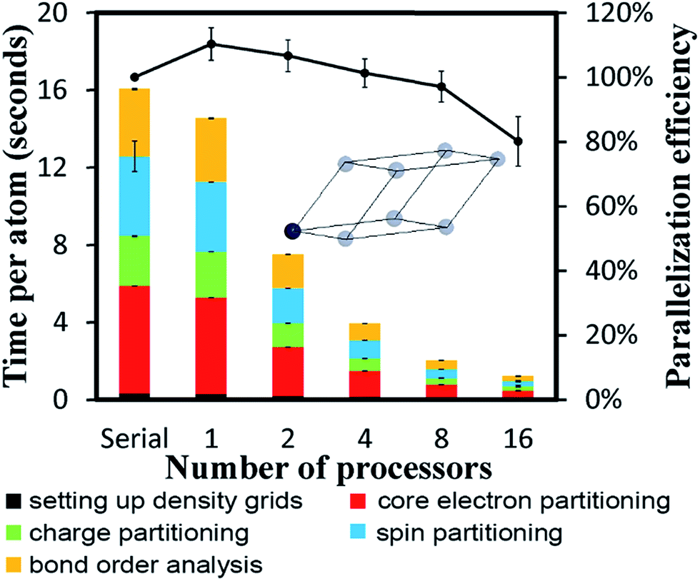 | ||
| Fig. 10 Parallelization timing and efficiency results for Ni bulk metal (1 atom per unit cell, PBE/planewave method). Three trials were performed to compute error bars for the computational times and parallelization efficiencies. | ||
Ni metal solid has a metallic bond. Ni atoms exchange electrons not only with the nearest neighbors, but also with the next nearest neighbors. The DDEC6 Ni–Ni bond orders for the Ni atom with one of its images were 0.281 for a nearest neighbor, 0.020 for a second nearest neighbor, 0.002 for a third nearest neighbor, and negligible for farther removed atoms. The DDEC6 SBO for the Ni atom in Ni metal was 3.54. Ni metal has ferromagnetic atomic spin distribution with a bulk magnetic moment of 0.6 per Ni atom.45 The DDEC6 Ni ASM was 0.645, which is in good agreement with this experimental value.
4.3 A large biomolecule: B-DNA decamer (CCATTAATGG)2
The B-DNA decamer (CCATTAATGG)2 contains 733 atoms per unit cell. As described in our earlier publication, the geometry of this system contains the experimental diffraction structure46 plus Na+ ions added to balance the charge.18 As shown in Fig. 11, the serial code required ∼9 seconds per atom to complete DDEC6 analysis. Bond order analysis was the most time consuming part of the calculation. The OpenMP code ran slightly faster on one processor than the serial (non-OpenMP) code. Parallelization efficiencies on 2, 4, 8, and 16 processors were >60%. This example shows efficient parallel DDEC6 computation for a large biomolecule.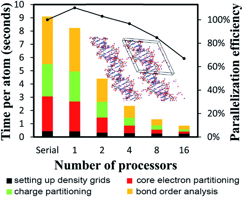 | ||
| Fig. 11 Parallelization timing and efficiency results for the B-DNA decamer (733 atoms per unit cell, PBE/planewave method). The lines mark the unit cell boundaries. | ||
Table 10 compares DDEC6 NACs to CHARMM27 and AMBER 4.1 forcefield NACs. We grouped the atoms by what they were bonded to. For example, C–C2H represents a C atom bonded to two C atoms and one H atom. The DDEC6 NACs per group have a small standard deviation (σ ≤ 0.10). With a few exceptions, DDEC6 NACs were similar to the CHARMM and AMBER NACs. The N–C2 and N–CH2 DDEC6 NACs are less negative than CHARMM and AMBER. The C–C2H and P DDEC6 NACs are between CHARMM and AMBER. The C–C2H2 DDEC6 NAC (−0.34) is slightly more negative than CHARMM (−0.18) and AMBER (−0.09).
| Group | DDEC6 NACs | DDEC6 SBOs | CHARMM27a | AMBER 4.1 | ||||||
|---|---|---|---|---|---|---|---|---|---|---|
| PBE/planewave | PBE/planewave | RESP HF/6-31G*b | ||||||||
| NAC | σ | Max | Min | SBO | σ | Max | Min | NAC | NAC | |
| a CHARMM27 NACs from ref. 47.b AMBER 4.1 RESP HF/6-31G* NACs from ref. 48. | ||||||||||
| C–C2H | −0.35 | 0.01 | −0.34 | −0.36 | 4.12 | 0.02 | 4.15 | 4.10 | −0.13 | −0.52 |
| C–C2H2 | −0.34 | 0.01 | −0.32 | −0.37 | 3.93 | 0.03 | 4.02 | 3.87 | −0.18 | −0.09 |
| C–C2HO | 0.14 | 0.05 | 0.20 | 0.07 | 3.84 | 0.02 | 3.88 | 3.78 | 0.15 | 0.12 |
| C–C2N | −0.07 | 0.02 | −0.05 | −0.09 | 4.11 | 0.03 | 4.15 | 4.05 | 0.14 | 0.14 |
| C–C3 | −0.06 | 0.01 | −0.04 | −0.06 | 4.04 | 0.03 | 4.08 | 4.01 | −0.15 | 0.00 |
| C–CH2O | 0.01 | 0.01 | 0.03 | −0.01 | 3.93 | 0.04 | 4.06 | 3.88 | −0.08 | −0.01 |
| C–CH3 | −0.39 | 0.00 | −0.38 | −0.39 | 4.03 | 0.03 | 4.09 | 4.00 | −0.11 | −0.23 |
| C–CHN | 0.04 | 0.05 | 0.10 | −0.01 | 4.01 | 0.06 | 4.09 | 3.92 | 0.11 | −0.12 |
| C–CHON | 0.27 | 0.01 | 0.29 | 0.24 | 3.87 | 0.02 | 3.92 | 3.83 | 0.16 | 0.03 |
| C–CN2 | 0.35 | 0.10 | 0.50 | 0.24 | 4.16 | 0.04 | 4.22 | 4.07 | 0.45 | 0.52 |
| C–CON | 0.49 | 0.01 | 0.51 | 0.47 | 4.18 | 0.04 | 4.25 | 4.13 | 0.52 | 0.51 |
| C–HN2 | 0.16 | 0.08 | 0.26 | 0.07 | 4.07 | 0.04 | 4.17 | 4.01 | 0.36 | 0.27 |
| C–N3 | 0.60 | 0.01 | 0.60 | 0.59 | 4.18 | 0.02 | 4.22 | 4.17 | 0.75 | 0.74 |
| C–ON2 | 0.59 | 0.01 | 0.62 | 0.57 | 4.25 | 0.02 | 4.28 | 4.21 | 0.52 | 0.68 |
| H–C | 0.09 | 0.05 | 0.34 | 0.03 | 1.00 | 0.03 | 1.11 | 0.93 | 0.10 | 0.13 |
| H–N | 0.31 | 0.02 | 0.35 | 0.27 | 0.96 | 0.04 | 1.01 | 0.89 | 0.34 | 0.41 |
| N–C2 | −0.42 | 0.07 | −0.30 | −0.55 | 3.30 | 0.03 | 3.36 | 3.24 | −0.70 | −0.69 |
| N–C2H | −0.44 | 0.01 | −0.43 | −0.45 | 3.58 | 0.05 | 3.65 | 3.51 | −0.40 | −0.68 |
| N–C3 | −0.13 | 0.03 | −0.10 | −0.17 | 3.66 | 0.04 | 3.73 | 3.57 | −0.14 | −0.01 |
| N–CH2 | −0.60 | 0.02 | −0.56 | −0.64 | 3.37 | 0.04 | 3.44 | 3.30 | −0.73 | −0.94 |
| O–C | −0.51 | 0.02 | −0.48 | −0.54 | 2.12 | 0.04 | 2.23 | 2.06 | −0.47 | −0.59 |
| O–C2 | −0.28 | 0.01 | −0.26 | −0.29 | 2.36 | 0.03 | 2.41 | 2.32 | −0.50 | −0.37 |
| O–CH | −0.49 | 0.04 | −0.45 | −0.53 | 2.30 | 0.10 | 2.41 | 2.18 | −0.66 | −0.59 |
| O–CP | −0.44 | 0.02 | −0.41 | −0.46 | 2.52 | 0.05 | 2.62 | 2.42 | −0.57 | −0.51 |
| O–P | −0.89 | 0.02 | −0.83 | −0.93 | 2.10 | 0.06 | 2.30 | 1.99 | −0.78 | −0.78 |
| P–O4 | 1.38 | 0.03 | 1.46 | 1.35 | 5.81 | 0.06 | 5.88 | 5.59 | 1.50 | 1.17 |
| Na | 0.90 | 0.03 | 0.92 | 0.77 | 0.32 | 0.02 | 0.40 | 0.29 | 1.00 | 1.00 |
Table 10 also lists the DDEC6 SBO for each atom type. The standard deviation was ≤0.10. SBOs for C atom types ranging from 3.84 to 4.25, which agrees with a chemically expected value of ∼4. The H atoms have DDEC6 SBOs of nearly 1, which is the chemically expected value. SBOs for N atoms were between 3 and 4. The O SBO is expected to be ∼2; however, we obtained O SBOs slightly higher than this. The SBOs for O can be slightly larger than 2 due to hydrogen bonding, lone pair (i.e., Lewis acid–base) interactions, or extra π-bonding interactions with adjacent atoms. DNA contains a phosphate group in which the hypercoordinate P atom has nearly six bonds (SBO = 5.81). Thus, the heuristic Lewis octet rule cannot describe DNA. The mostly ionic Na atom had SBO = 0.32 due to a small amount of electron exchange with the nearest O and P atoms.
Fig. 12 shows the individual bond orders. The alternating double and single bonds in aromatic rings is merely a drawing convention to indicate the degree of unsaturation of the ring, and it does not imply that these bond orders are actually alternating double and single bonds. Rather, all bond orders in these aromatic rings are intermediate between single and double bonds. Two P–O bonds in the PO4 group are shorter and of higher order than the other two. The DNA double helix structure was first introduced by Watson and Crick in 1953, being held together by hydrogen bonds.49 There are three hydrogen bonds connecting guanine to cytosine and two connecting adenine to thymine.50,51 These are displayed in Fig. 12 as dashed red lines and had bond orders of 0.05 to 0.12.
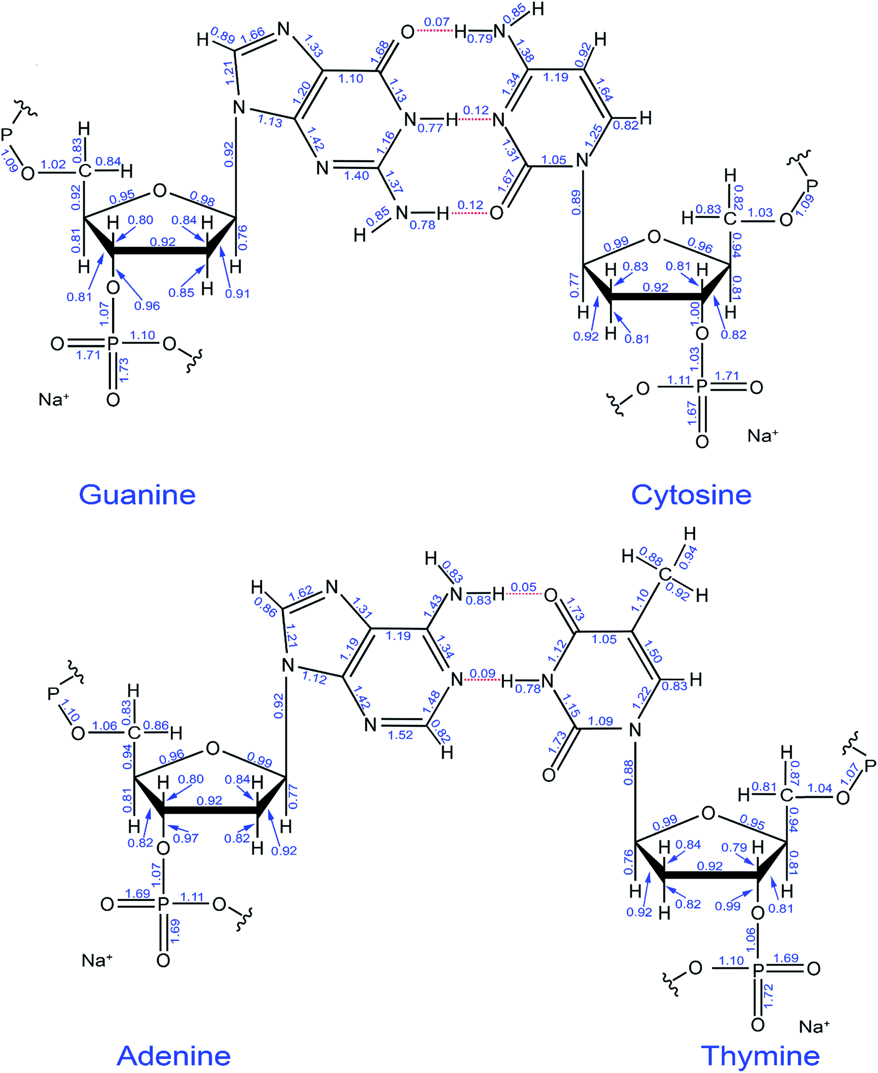 | ||
| Fig. 12 Computed DDEC6 bond orders in the guanine-cytosine and adenine-thymine base pairs. The hydrogen bonds are shown as dotted red lines. | ||
4.4 Single molecule magnets with collinear and non-collinear magnetism
We now discuss computational performance for two single molecule magnets that demonstrate versatility of our computational approach. Fig. 13 displays results for the Mn12-acetate single molecule magnet using both planewave (left panel) and Gaussian (middle panel) type basis sets. Mn12-acetate has been one of the most widely studied single molecule magnets.52–54 As shown in Fig. 13, computational times were much higher for the Gaussian basis set coefficients input than for the density grid input derived from the planewave calculation. The program must explicitly compute the electron and spin density grids from the Gaussian basis set coefficients input. Parallelization efficiencies on 2, 4, 8, and 16 parallel processors were >73% for the density grid input and >53% for the Gaussian basis set coefficients input. The slightly lower parallelization efficiency for the Gaussian basis set coefficients input is partially due to the presence of some ATOMIC memory write statements (in which only one parallel processor can write a result to memory at a time) in the module that computes the electron and spin density grids.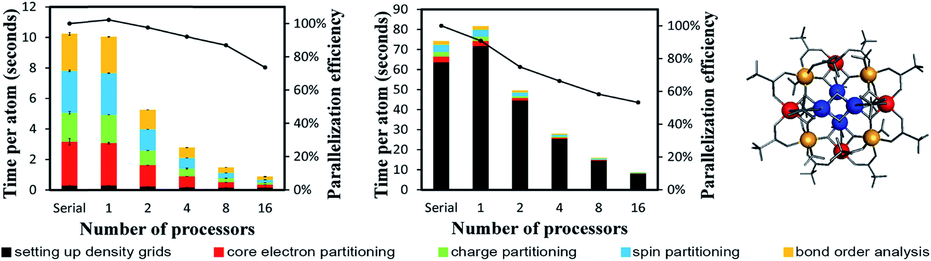 | ||
| Fig. 13 Parallelization timing and efficiency results for the Mn12-acetate single molecule magnet (148 atoms per unit cell) that exhibits collinear magnetism. Left: PBE/planewave results. Middle: PBE/LANL2DZ results. Right: Chemical structure with Mn atoms colored by type: Mn type 1 (blue), Mn type 2 (red), Mn type 3 (yellow). The PBE/LANL2DZ computed ASMs were −2.56 (Mn type 1), 3.63 (Mn type 2), 3.57 (Mn type 3), and ≤0.077 in magnitude on all other atoms.18 | ||
Fig. 14 illustrates the computed NACs and bond orders for the Mn12-acetate single molecule magnet (LANL2DZ basis set). The Mn atoms had NACs of 1.31–1.42 and were bonded to adjacent oxygen atoms via bond orders 0.28–0.56. The C–O bond orders in the acetate groups were 1.29–1.41. A water molecule coordinates to each Mn type 3 atom via an oxygen lone pair (i.e., Lewis acid–base interaction) having a bond order of 0.32. The Mn type 1 atoms form a Mn4O4 cuboidal core in which the Mn–O bond order along each edge of the cuboid is 0.45. The CH3 group in each acetate carries an almost neutral net charge, while the CO2 group in each acetate carries a net charge of ∼ −0.4 e. DDEC6 SBOs for each chemical element were 2.66–3.16 (Mn), 1.88–2.18 (O), 3.83–3.86 (C), and 0.81–0.98 (H). Mn SBOs were 3.16 (type 1), 2.74 (type 2), and 2.66 (type 3). Results for the planewave basis set were similar. Specifically, the root-mean-squared difference between the PBE/planewave and PBE/LANL2DZ calculated DDEC6 results were 0.035 (NACs), 0.067 (ASMs), and 0.110 (SBOs) for this material. The maximum absolute differences were 0.098 (NACs), 0.252 (ASMs), and 0.222 (SBOs). This basis set stability occurs because DDEC6 analysis formally depends on the electron and spin distributions irrespective of the basis set employed.17
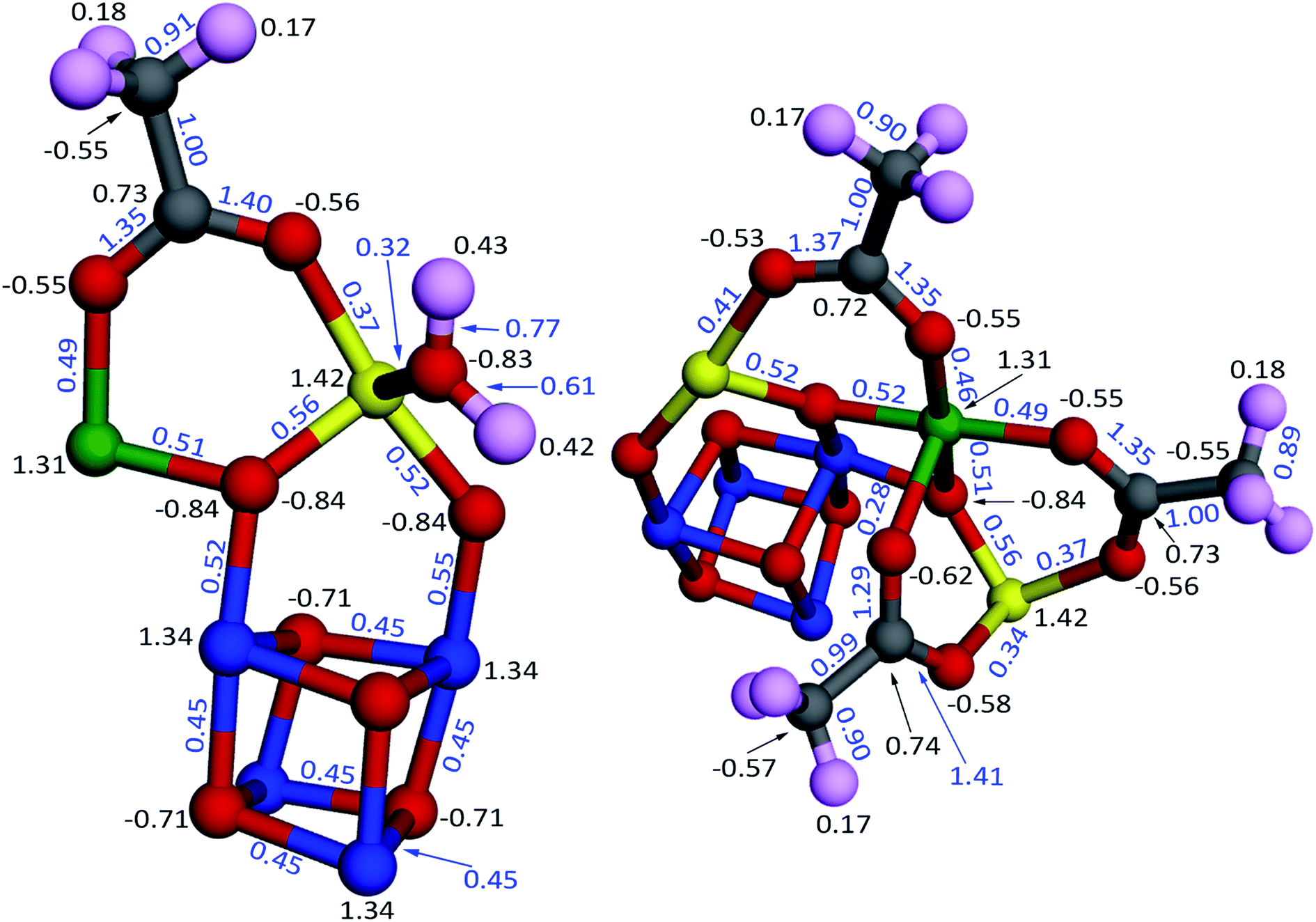 | ||
| Fig. 14 Computed bond orders (blue) and NACs (black) for the Mn12-acetate single molecule magnet using the PBE/LANL2DZ electron and spin densities. The atoms are colored by element: Mn type 1 (blue), Mn type 2 (green), Mn type 3 (yellow), O (red), C (grey), H (pink). All of the atoms (i.e., the full chemical structure) were included the DDEC6 calculation, but for display purposes only a portion of the atoms are shown here. The fragments shown here were chosen so that together they include all of the symmetry unique atoms and bonds. | ||
DDEC6 analysis of planewave non-collinear magnetism is also computationally efficient. As shown in Fig. 15, ∼12 seconds per atom on a single processor were required to complete DDEC6 analysis for the Fe4O12N4C40H52 non-collinear single molecule magnet. Parallelization efficiencies were >57% on 2, 4, 8, and 16 parallel processors. The computed NACs and bond orders are displayed in Fig. 16.
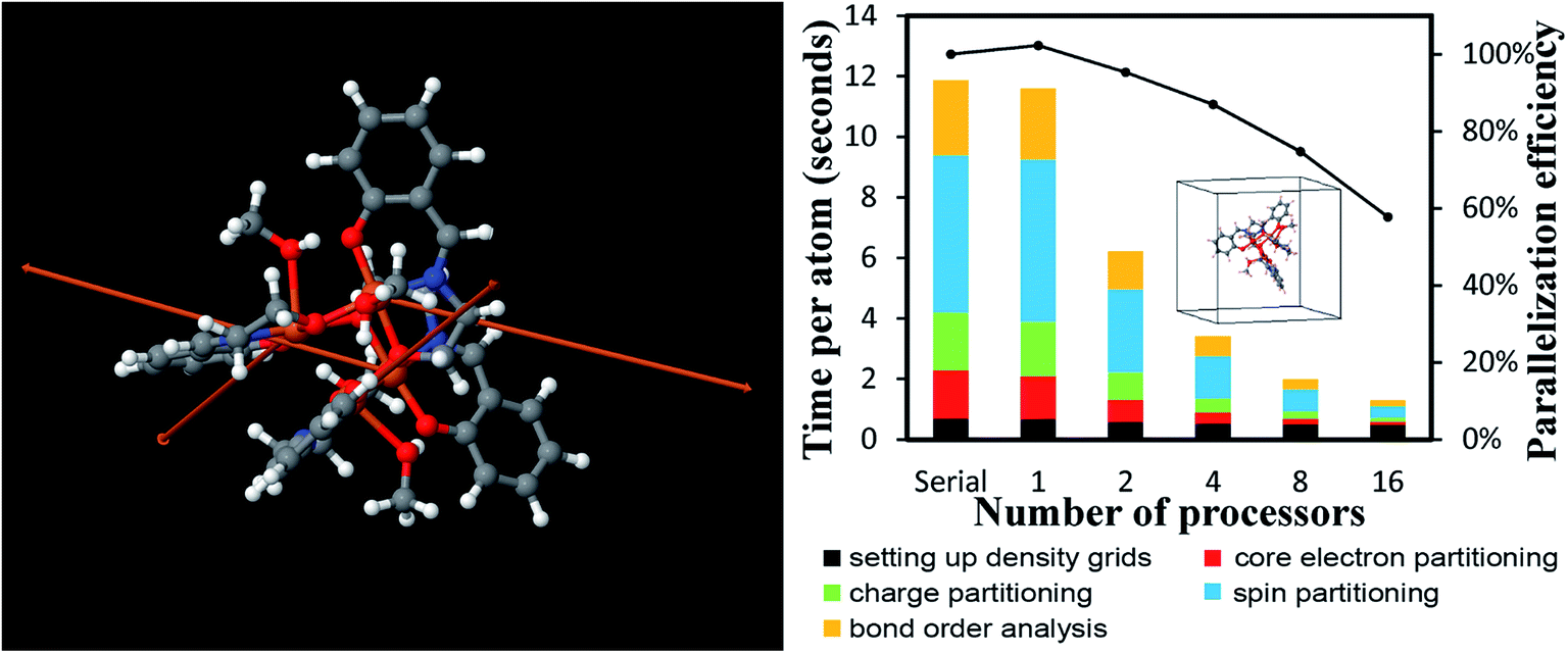 | ||
| Fig. 15 Parallelization timing and efficiency results for the Fe4O12N4C40H52 single molecule magnet (112 atoms per unit cell, PW91/planewave method) that exhibits non-collinear magnetism. Left: Chemical structure reproduced with permission of ref. 16 (© The Royal Society of Chemistry 2017). The atoms and spin magnetization vectors are colored by: Fe (orange), O (red), N (blue), C (gray), H (white). The Fe atoms exhibited DDEC6 ASM magnitudes of 2.33, and the ASM magnitudes were negligible on the other atoms.18 Right: Parallelization timing and efficiency results. | ||
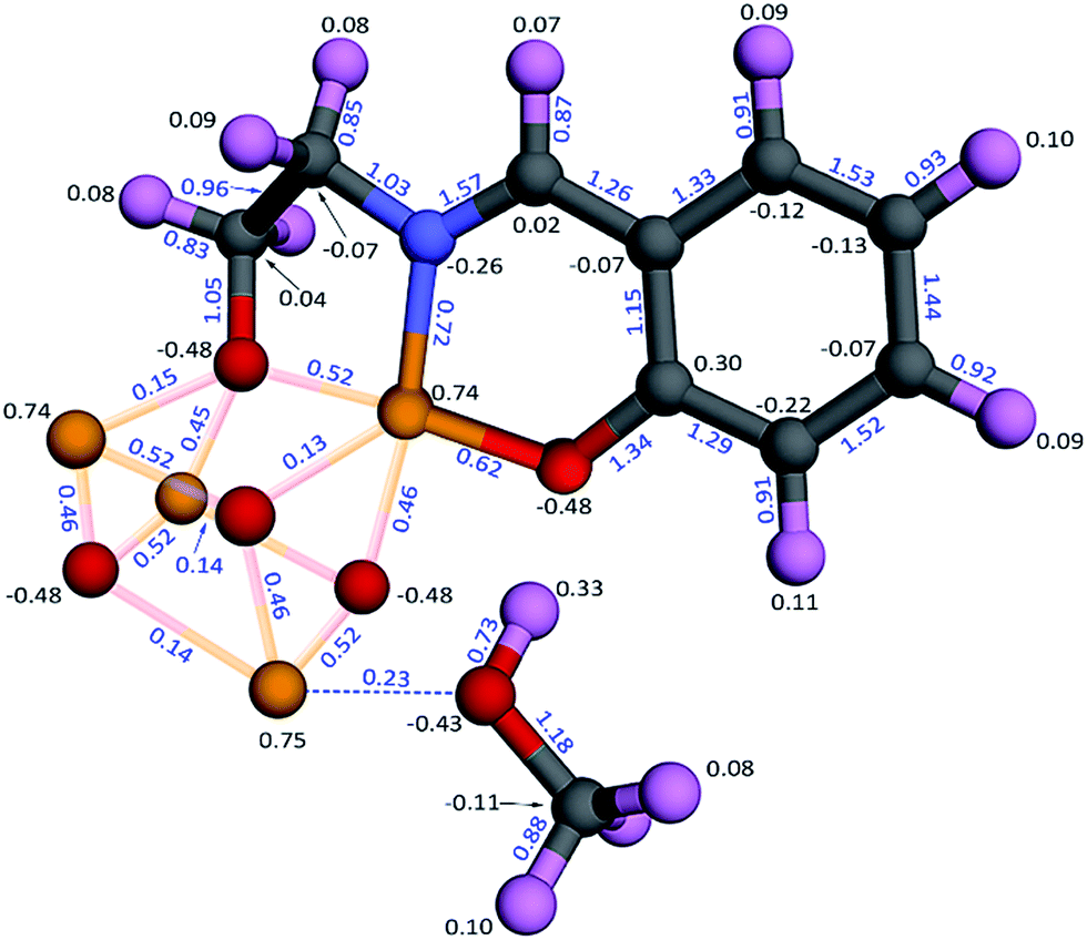 | ||
| Fig. 16 Computed bond orders (blue) and NACs (black) for the Fe4O12N4C40H52 single molecule magnet that exhibits non-collinear magnetism. The atoms are colored by element: Fe (yellow), O (red), C (grey), N (blue), H (pink). The distorted cuboidal Fe4O4 core is shown together with one adsorbed methanol molecule and one of the organic ligands. The dashed blue line illustrates interaction between the methanol lone pair and the adjacent Fe atom (i.e., Lewis acid–base interaction). The other three adsorbed methanol molecules and three organic ligands were included in the calculation but are not shown here for display purposes. | ||
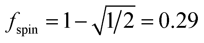
As described by eqn (12)–(14), the number of iterations (aka ‘spin cycles’) required to converge the DDEC ASMs to within a chosen spin_convergence_tolerance is extremely predicable. As an example, Fig. 17 plots the natural logarithm of the magnitude of the largest change in ASM component between successive iterations (aka ‘max_ASM_change’) for the Mn12-acetate (PBE/planewave and PBE/LANL2DZ) and Fe4O12N4C40H52 single molecule magnets. These were chosen as examples to illustrate the rate of ASM convergence is independent of the basis sets and the same for collinear and non-collinear magnetism. Each of these data sets was fitted to a straight line using linear regression. For each line the value of fspin can be calculated as exp(slope). The fspin values of 0.29, 0.27, and 0.29 obtained by fitting these three datasets is in nearly perfect agreement with the value theoretically predicted in eqn (12). Results for all of the magnetic systems we examined to date confirm that the rate of ASM convergence follows eqn (12)–(14) independently of the magnetic material and basis sets. In all cases, ASM convergence was computationally inexpensive and required few iterations.
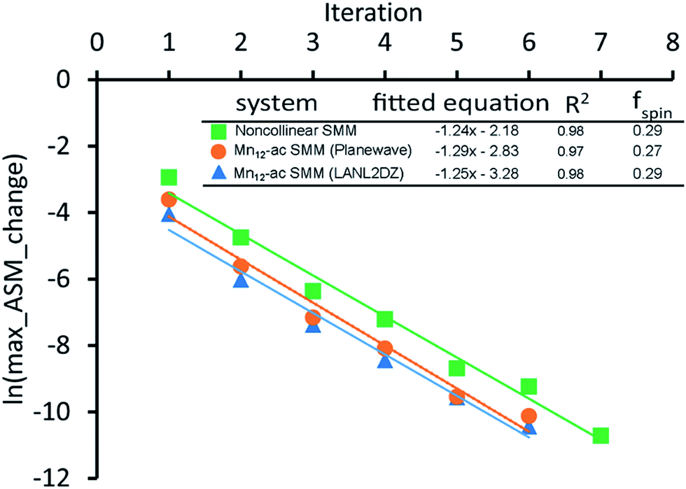 | ||
Fig. 17 The convergence rate of spin partitioning is highly predictable. A plot of the logarithm of the max_ASM_change versus iteration number is linear with a slope equal to 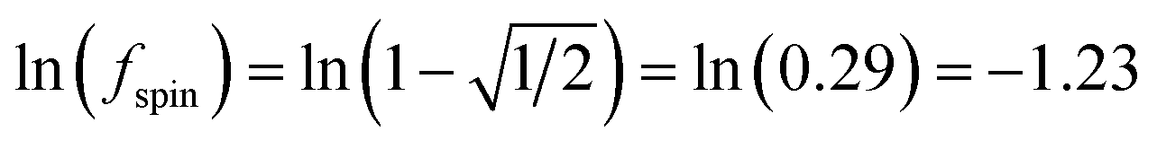 for both collinear and non-collinear magnetism. for both collinear and non-collinear magnetism. | ||
4.5 Linear scaling computational cost: ice supercells
In this example, we study how the computational time and required memory scale when increasing the unit cell size and number of parallel processors. We analyzed ice crystals with 12, 96, 324, 768, 1500, 2592, 4116, 6144, and 8748 atoms in the unit cell. As described in another paper, these structures were constructed as n × n × n times the primitive cell containing 4 water molecules (12 atoms), for n = 1 to 9.16 These unit cells were used as inputs for VASP calculations to compute the electron distributions.16 As shown in Fig. 18, the total memory required is almost independent of the number of processors and scales linearly with increasing system size. This indicates an efficient memory management. Fig. 18 also shows the serial and parallel computational times scaled linearly with increasing system size and decreased with increasing number of parallel processors. Table 11 shows how the data from Fig. 18 fits to lines of the form y = axb for the time and memory needed to complete the CHARGEMOL program. The fitted exponents b are 0.8723 to 1.0389, which indicates almost perfect linear scaling. For 8748 atoms, parallelization efficiencies were >71% on 2, 4, 8, and 16 processors.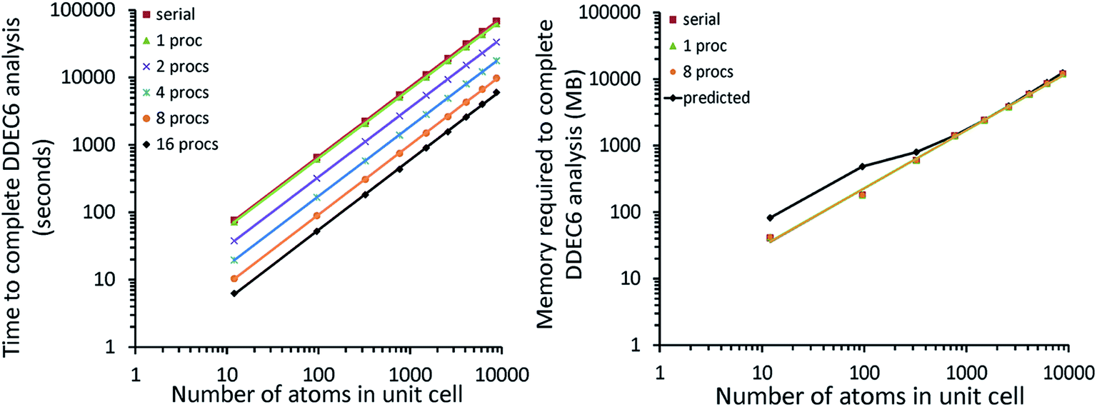 | ||
| Fig. 18 DDEC6 results for ice crystal using 12, 96, 324, 768, 1500, 2592, 4116, 6144, and 8748 atoms per unit cell (PBE/planewave method). These results show both the computational time and memory required scale linearly with increasing system size. Left: The computational time scales linearly with the number of atoms and decreases with increasing number of processors. Right: Total RAM required is almost independent of the number of processors. The predicted memory required is from eqn (17). | ||
| Processors | Time | Memorya | Parallelization efficiency | ||||
|---|---|---|---|---|---|---|---|
| a | b | R2 | a | b | R2 | ||
| a The memory tests were performed on the Comet cluster at the San Diego Supercomputing Center (SDSC) with the serial code and parallel code using one and eight cores. | |||||||
| Serial | 5.8719 | 1.0313 | 1.0000 | 4.0197 | 0.8750 | 0.9976 | 100.0% |
| 1 | 5.5777 | 1.0268 | 1.0000 | 4.1063 | 0.8723 | 0.9973 | 109.3% |
| 2 | 2.9132 | 1.0294 | 1.0000 | N.A. | N.A. | N.A. | 102.5% |
| 4 | 1.4975 | 1.0319 | 1.0000 | N.A. | N.A. | N.A. | 96.5% |
| 8 | 0.7803 | 1.0363 | 0.9999 | 4.1063 | 0.8723 | 0.9973 | 87.6% |
| 16 | 0.4578 | 1.0389 | 1.0000 | N.A. | N.A. | N.A. | 71.2% |
The DDEC6 O NACs ranged from −0.84 to −0.87. The DDEC6 bond orders for H and O in the same molecule were 0.79–0.80, while the bond order between O and the nearest H from another molecule (i.e., hydrogen bond) was 0.08–0.09.
We tested the DDEC6 time and memory requirements to analyze VASP electron density distributions with 12700800 (196 × 216 × 300), 35123200 (280 × 280 × 448), and 8128120 (360 × 384 × 588) grid points in the unit cell containing 324 atoms. Fig. 19 shows that time and memory scale linearly with respect to the number of grid points. Changing the number of k-points or planewave cutoff energy in VASP without changing the number of grid points does not change the DDEC6 analysis time and memory requirements. As shown in Fig. 19, using a planewave cutoff energy of 400 or 750 eV gives the same DDEC6 analysis time and memory requirements. We also tested the time required to complete DDEC6 analysis for 12700800 grid points with the number of k-points defined by eqn (21) and (22). Changing the number of k-points did not change the DDEC6 analysis time.
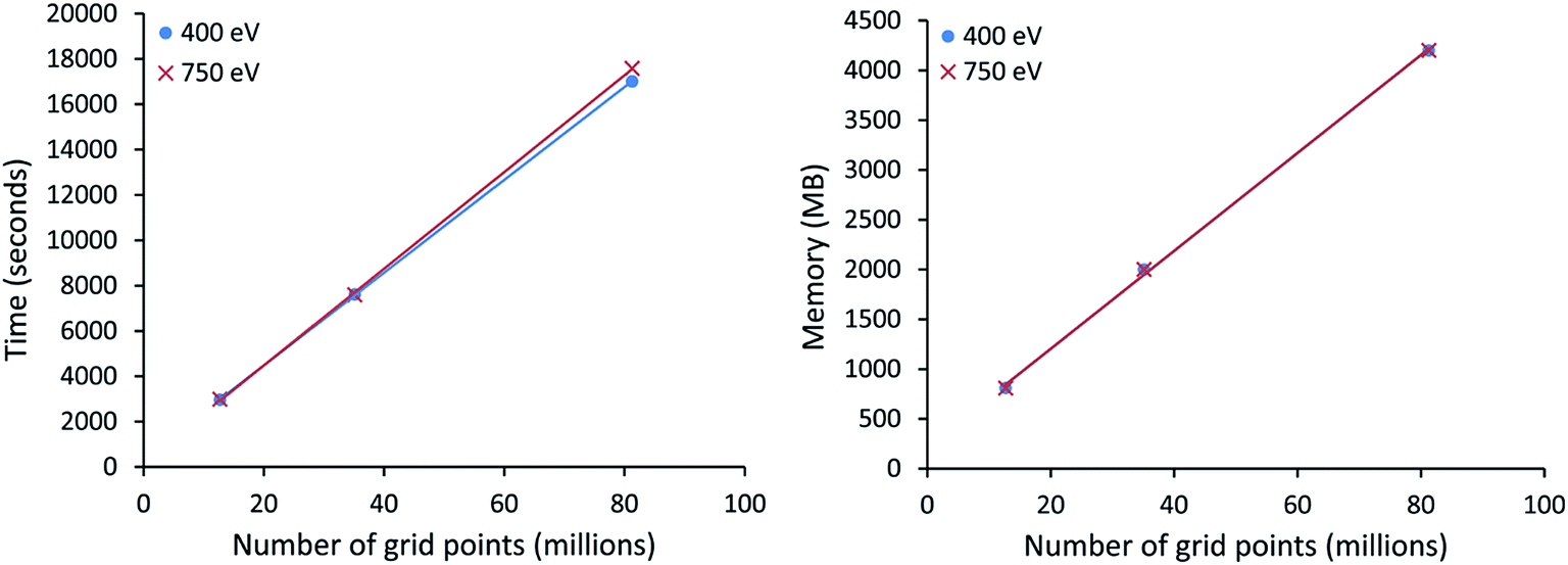 | ||
| Fig. 19 Time and memory required to complete DDEC6 analysis for a 324 atom ice unit cell with 12700800, 35123200, and 81285120 grid points. These calculations were run in serial mode on a single processor. Both the computational time and memory required scaled linearly with increasing number of grid points and were independent of the planewave cutoff energy. | ||
4.6 Numerical precision: effects of grid spacing, k-point mesh, and planewave cutoff energy
For periodic materials, calculations using a planewave basis set have several advantages.26,55 First, the basis set functions are orthonormal, which greatly simplifies matrix element calculations. Second, the planewave coefficients are related to a Fourier transform.26,55 Fast Fourier transform algorithms allow functions to be quickly transformed between real space and reciprocal space. Because the standard fast Fourier transform algorithm requires uniformly spaced sampling points, uniformly spaced integration grids are the natural choice for planewave QC calculations. Integrations and other mathematical manipulations can thus be performed in whichever space (real or reciprocal) is most convenient.26 Third, the wavefunction for a periodic material can be described in terms of Bloch waves, where each one-particle Bloch wave has the form in eqn (18).55
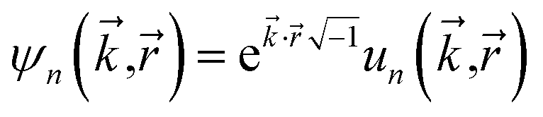 | (18) |
Because the cell periodic functions {un(![[k with combining right harpoon above (vector)]](https://www.rsc.org/images/entities/i_char_006b_20d1.gif) ,)} have the same periodicity as the unit cell, they can be expanded in terms of a basis set of planewaves commensurate with the unit cell.55 Fourth, a planewave basis set systematically approaches completeness as the cutoff energy is raised.26 All commensurate planewaves with kinetic energy below this cutoff energy are included in the basis set.26 (Basis sets comprised of psinc functions combine the advantages of planewaves and localized basis functions,42,56,57 but psinc basis functions were not used here.)
,)} have the same periodicity as the unit cell, they can be expanded in terms of a basis set of planewaves commensurate with the unit cell.55 Fourth, a planewave basis set systematically approaches completeness as the cutoff energy is raised.26 All commensurate planewaves with kinetic energy below this cutoff energy are included in the basis set.26 (Basis sets comprised of psinc functions combine the advantages of planewaves and localized basis functions,42,56,57 but psinc basis functions were not used here.)
The k-points {} sample the primitive cell in reciprocal space (aka ‘the first Brillouin zone’).55 More k-points corresponds to a finer integration mesh in reciprocal space. A sufficiently large number of k-points is needed to achieve accurate integrations.58 Because the volumes of the real-space and reciprocal-space unit cells are inversely proportional,55 a constant volume per integration point in reciprocal space is defined by keeping the total number of k-points
 | (19) |
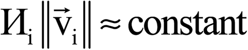 | (20) |
 is the number of k-points along the ith lattice vector. For a ‘fine’ k-point mesh spacing, we set the constant on the right-side of eqn (20) to ≥16 Å:
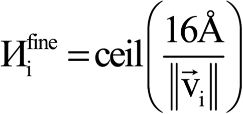 | (21) |
 | (22) |
 ), and the Gamma point (i.e., = 0) was used for single k-point (i.e.,
  ) grids.
The projector augmented wave (PAW) method is an all-electron frozen core method that combines high computational efficiency with high accuracy.59,60 The VASP PAW potentials use a high-level relativistic calculation for the frozen-core electrons and a scalar-relativistic approximation for the valence electrons.26 The PAW method applies a projection to the all-electron density to produce a pseudized valence density that varies more slowly near the atomic nucleus than the true valence density.59,60 This pseudized valence density can thus be accurately computed using a planewave basis with a moderate energy cutoff.59,60 Once the accurate pseudized valence density is computed, the inverse projectors can be applied to recover the true valence density.59,60 The planewave cutoff energy required to achieve well-converged results depends on the ‘hardness’ of the PAW potentials used. A ‘harder’ PAW potential has a smaller effective core radius, which makes it more accurately transferable between materials but at the expense of requiring a higher energy cutoff to achieve well-converged results.60
The VASP POTCAR file (which contains the PAW potential) lists the ‘ENMAX’ value; this is the planewave cutoff energy beyond which results are considered well-converged. A reasonable choice is to set the planewave cutoff energy (ENCUT) to the greater of 400 eV and the POTCAR-listed ENMAX value:
| ENCUT = max(400 eV, ENMAX) | (23) |
The number of real-space grid points required to accurately sample the electron and spin density distributions is directly given by the Sampling Theorem. According to the Sampling Theorem that was developed by several pioneers of signal transmission, a continuous signal can be transmitted and recovered without aliasing (also called wrap-around or folding) errors if it is sampled at least as frequently as twice the highest frequency component of the signal.61–63 This minimum sampling rate is called the Nyquist rate.61,62,64 Thus, the orbitals will be accurately represented on a real-space grid without aliasing errors if the real-space grid contains twice as many grid points along each lattice direction as basis set planewave components along the corresponding lattice direction. Because the electron and spin density distributions are generated from summed second-order orbital products, their maximum frequency component is twice that of the orbitals. Therefore, the minimum sampling rate along each lattice direction for electron and spin density distributions is twice that of the orbitals.
The PREC tag in VASP defines the number of real-space grid points.65 PREC = Accurate chooses real-space grids of sufficient resolution to avoid aliasing errors when representing the orbitals and electron and spin distributions.65 As required by the Sampling Theorem, PREC = Accurate uses a grid-for-orbitals with at least twice as many grid points as basis set planewave components along each lattice direction.65 PREC = Accurate also uses a grid-for-densities (for electron and spin magnetization densities and potentials) that contains twice as many grid points along each lattice direction as the grid-for-orbitals.65 A PREC = Accurate or finer resolution real-space grid is thus highly recommended. For a planewave cutoff energy of 400 eV, a PREC = Accurate grid corresponds to an electron density grid spacing of ∼0.14 bohr and a volume per grid point of ∼0.0027 bohr3.
We studied numerical precision of DDEC6 analysis when changing the number of k-points, the cutoff energy, and the grid spacing in VASP. We performed tests for the 324 atom ice unit cell, whose unit cell is 3 × 3 × 3 times the primitive cell. The primitive cell has eight H atoms and four O atoms. Each atom of the primitive cell was defined as an atom type, resulting in 12 atom types. The parameter sets used to test the DDEC6 analysis precision are defined in Table 12. Fine and very fine k-point meshes were used. We also varied the number of electron density grid points (196 × 216 × 300, 320 × 320 × 500, and 360 × 384 × 588) and planewave energy cutoff (400 and 750 eV). (The grid for orbitals contained half as many points along each lattice direction). For sets one to four, the number of grid points along at least one of the lattice vectors was not evenly divisible by 3. Because the unit cell is 3 × 3 × 3 times the primitive cell, this caused some atoms of the same type to have different positions relative to their nearest grid point. This situation was chosen to maximize the MAD defined below. The grid for sets 5 and 6 had number of grid points along each lattice vector evenly divisible by 3, which resulted in all atoms of the same type having identical positions relative to their nearest grid point. This situation was chosen to minimize the MAD defined below.
| Descriptor | Set 1 | Set 2 | Set 3 | Set 4 | Set 5 | Set 6 |
|---|---|---|---|---|---|---|
| Computational settings | ||||||
| Cutoff energy (eV) | 750 | 400 | 750 | 750 | 400 | 750 |
| Volume per grid point (bohr3) | 0.001858 | 0.001858 | 0.001858 | 0.000461 | 0.000290 | 0.000290 |
| k-points |  |
 |
 |
 |
 |
 |
|
||||||
| Mean absolute deviation (MAD) | ||||||
| NAC | 0.000394 | 0.000377 | 0.000394 | 0.000299 | 0.000020 | 0.000019 |
| Atomic dipole magnitude | 0.000191 | 0.000181 | 0.000191 | 0.000144 | 0.000010 | 0.000011 |
| Max quadrupole eigenvalue | 0.000120 | 0.000122 | 0.000120 | 0.000071 | 0.000003 | 0.000003 |
| SBO | 0.000516 | 0.000455 | 0.000516 | 0.000431 | 0.000027 | 0.000025 |
| Density tail exponent | 0.000236 | 0.000242 | 0.000236 | 0.000212 | 0.000005 | 0.000005 |
| r-cubed moment | 0.004803 | 0.004343 | 0.004806 | 0.003095 | 0.000128 | 0.000120 |
|
||||||
| Mean absolute deviation of mean (MADM) | ||||||
| NAC | 0.000348 | 0.001670 | 0.000348 | 0.000071 | 0.001912 | 0 |
| Atomic dipole magnitude | 0.000114 | 0.000486 | 0.000114 | 0.000065 | 0.000527 | 0 |
| Max quadrupole eigenvalue | 0.000083 | 0.000286 | 0.000083 | 0.000049 | 0.000286 | 0 |
| SBO | 0.000502 | 0.001851 | 0.000502 | 0.000133 | 0.001897 | 0 |
| Density tail exponent | 0.000359 | 0.000783 | 0.000358 | 0.000173 | 0.000351 | 0 |
| r-cubed moment | 0.003289 | 0.005633 | 0.003284 | 0.002817 | 0.007167 | 0 |
For each atom in the material, we computed the following DDEC6 atomistic descriptors: (a) NAC, (b) atomic dipole magnitude, (c) largest eigenvalue of the atomic traceless quadrupole matrix, (d) SBO, (e) density tail exponent, and (f) r-cubed moment. For each set in Table 12, we computed the mean absolute deviation (MAD) for each atomistic descriptor ( ) using eqn (24).
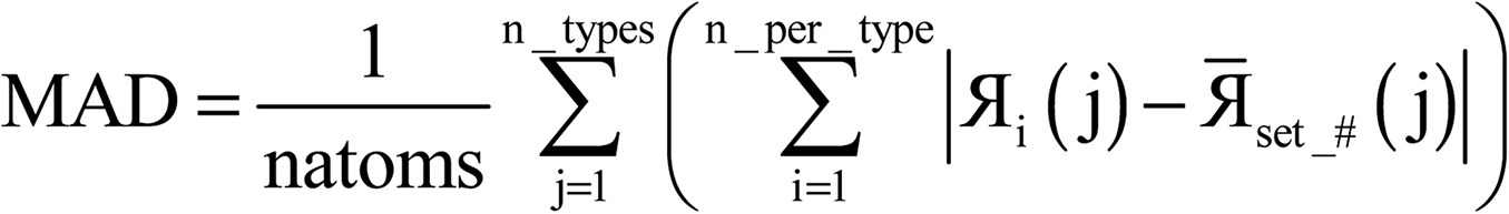 | (24) |
 stands for the atomistic descriptor value for the ith atom of a particular atom type j.
  is the average value of the atomistic descriptor across the same atom type j for a single QC calculation (i.e., set_1, set_2, set_3, set_4, set_5, or set_6). The high_precision DDEC6 results (i.e., set_6) were used as reference to measure the mean absolute deviation of mean (MADM) of the DDEC6 atomistic descriptors. The MADM was computed for each atomistic descriptor as in eqn (25).
 | (25) |
The MAD quantifies how much uncertainty there is in the computed value of a descriptor due to non-systematic errors. The MADM quantifies how much uncertainty there is in the computed value of a descriptor due to systematic errors. The sum of the MAD and MADM quantifies how much total uncertainty (non-systematic + systematic error) there is in computing the descriptor's value.
The average absolute value of each of the six descriptors was 0.571 for NAC, 0.039 for atomic dipole magnitude, 0.037 for max quadrupole eigenvalue, 1.28 for SBO, 1.77 for density tail exponent, and 10.67 for r-cubed moment. The MAD was 3.2–4.5 (NAC), 2.3–3.6 (atomic dipole magnitude), 2.5–4.1 (max quadrupole eigenvalue), 3.4–4.7 (SBO), 3.6–5.5 (density tail exponent), and 3.3–4.9 (r-cubed moment) orders of magnitude smaller than these values. Thus, the MAD was relatively small in all cases. As shown in Table 12, the MAD was smallest for sets 5 and 6, which used the smallest volume per grid point. The intermediate grid spacing (set 4) had intermediate MAD values. The k-points and planewave cutoff energy had negligible effect on the MAD values. This shows the MAD values were most strongly influenced by the integration grid spacing.
As shown in Table 12, the MADM was also small in all cases. The planewave cutoff energy had the largest effect on the MADM. The higher cutoff energy (750 eV) had substantially smaller MADM than the lower cutoff energy (400 eV). The k-points had negligible effect on the MADM. At high cutoff energy, decreasing the volume per grid point decreased the MADM.
From the tests performed, we conclude that VASP calculations using a PREC = Accurate integration grid, a planewave cutoff energy of 400 eV, and k-points defined by  will produce an accurate electron density distribution suitable for DDEC6 analysis. If a ‘hard’ PAW potential is used, the energy cutoff should be increased to at least ENMAX. Finer integration grid spacing, higher planewave cutoff energy, and more k-points can be used if extremely high precision is desired.
4.7 Different levels of theory applied to the ozone molecule
The DDEC6 method works with any QC method capable of providing accurate electron and spin density distributions.18 To be accurate, the QC method should include electron exchange–correlation effects.66 Examples of appropriate QC methods include: DFT methods, DFT + U,67 DFT + dispersion corrections,68 coupled cluster methods (e.g., CCSD and SAC-CI), configuration interaction methods (e.g., CISD, CAS-SCF, etc.).As an example, illustrating diverse exchange–correlation theories, Fig. 20 shows computational timings for ozone singlet, cation doublet, and triplet states computed using B3LYP,69,70 PW91,71 CCSD,72 CAS-SCF,73 and SAC-CI74,75 methods. SZ = 1 (B3LYP, PW91, and CCSD) and SZ = 0 (CAS-SCF and SAC-CI) for the computed triplet state.28 Because the DDEC6 calculation had to compute the density grids from the Gaussian basis set coefficients, the computational times per atom were larger for the larger basis set (i.e., AUG-cc-pVTZ76) than for the smaller basis set (i.e., 6-311+G*). Computing the density grids from the Gaussian basis set coefficients was the most computationally demanding part of the calculation. Times for the serial calculations ranged from ∼11 to ∼94 seconds per atom. Parallelization efficiencies for 16 processors were ≥∼50%.
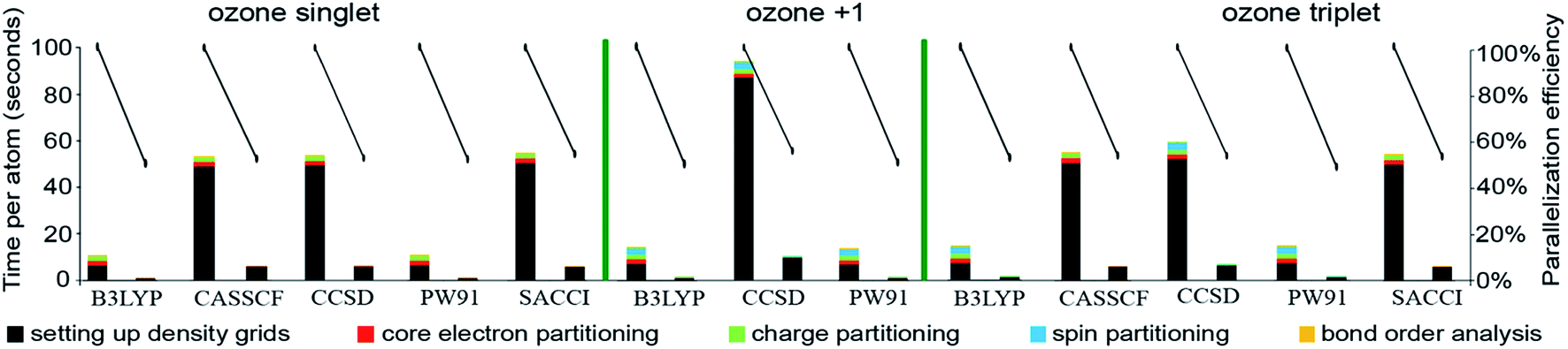 | ||
| Fig. 20 Parallelization timing and efficiency results for ozone singlet, +1 doublet, and triplet at different levels of theory: B3LYP/6-311+G*, CASSCF/AUG-cc-pVTZ, CCSD/AUG-cc-pVTZ, PW91/6-311+G*, and SAC-CI/AUG-cc-pVTZ. Serial and 16 parallel processors calculations are compared. | ||
The cation spin doublet calculation at the CCSD/AUG-cc-pVTZ level of theory took the longest time for DDEC6 analysis. To verify this was statistically significant, we performed three serial runs each for the cation doublet and neutral triplet at CCSD/AUG-cc-pVTZ. The average and error bars (i.e., standard deviation) for each part of the calculation are shown in Fig. 20 but are too small to be visible. These results showed that indeed it took a statistically significantly longer time for setting up the density grids for the cation doublet than for the neutral triplet at CCSD/AUG-cc-pVTZ.
Fig. 21 plots the logarithm of the DDEC6 bond orders versus bond lengths. Interestingly, B3LYP gave an asymmetric geometry having different distances between the middle and two outer O atoms for the triplet state, while CCSD yielded an asymmetric geometry for the cation doublet state. The other geometries were symmetric. The data was fit to four straight lines: (a) singlet and triplet ![[O with combining low line]](https://www.rsc.org/images/entities/char_004f_0332.gif) ––O bond, (b) cation doublet ––O bond, (c) singlet and triplet –O– bond, and (d) cation doublet –O– bond. The squared correlation coefficients >0.93 confirm an approximate exponential decay in DDEC6 bond order with increasing bond length for a given bond. The DDEC6 bond orders depended primarily on the bond lengths and electronic state, without an explicit dependence on the exchange–correlation theory. The choice of exchange–correlation theory affects the computed DDEC6 bond orders only to the extent the electron and spin distributions are affected.
––O bond, (b) cation doublet ––O bond, (c) singlet and triplet –O– bond, and (d) cation doublet –O– bond. The squared correlation coefficients >0.93 confirm an approximate exponential decay in DDEC6 bond order with increasing bond length for a given bond. The DDEC6 bond orders depended primarily on the bond lengths and electronic state, without an explicit dependence on the exchange–correlation theory. The choice of exchange–correlation theory affects the computed DDEC6 bond orders only to the extent the electron and spin distributions are affected.
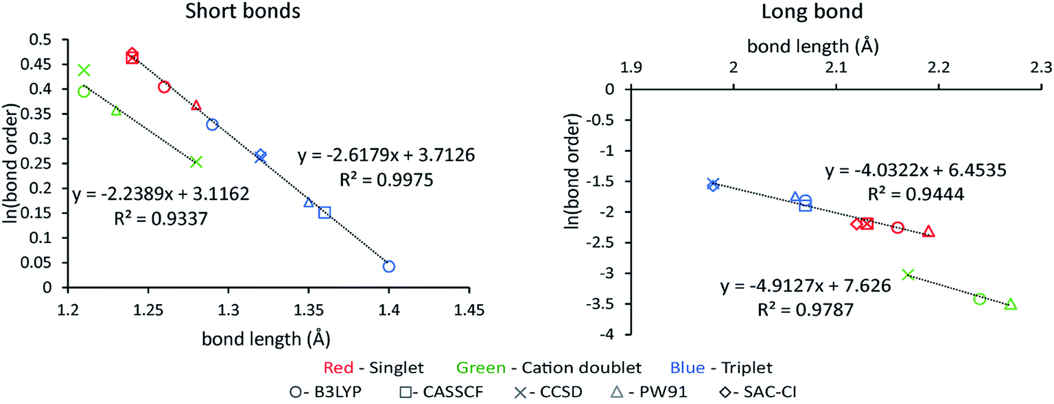 | ||
| Fig. 21 Logarithm of bond order versus bond length for ozone molecule. Colors of data points indicate singlet (red), cation doublet (green), or triplet (blue) spin states. Shapes of data points indicate the exchange–correlation theory. Left: Bonds between the middle and outer atoms. Right: Bond between the two outer atoms. | ||
Pauling suggested a Δ(bond length) to Δ(ln(bond order)) ratio of ∼0.3, but noted this value should depend on the kind of atom and type of bond.77 Our results agree with this. For the four fitted lines, we obtained ratios of (a) 1/2.6179 = 0.38, (b) 1/2.2389 = 0.45, (c) 1/4.0322 = 0.25, and (d) 1/4.9127 = 0.20.
Table 13 summarizes the NACs for the O atoms in ozone as a range across the levels of theory studied. The maximum variation in NAC was 0.107 for the two terminal atoms of the +1 doublet when using CCSD. As explained above, CCSD yielded an asymmetric geometry for the cation doublet; this caused the two terminal O atoms to be distinct with different NACs. The second largest variation was the central O atom in an ozone triplet where NACs go from 0.134 (CASSCF) to 0.236 (CCSD). Overall, these results show the DDEC6 method can be successfully applied to different exchange–correlation theories.
| Spin state | NACs | |
|---|---|---|
| –O– |
O––O |
|
| Singlet | −0.179–−0.195 | 0.357–0.389 |
| +1 doublet | 0.231–0.338 | 0.431–0.515 |
| Triplet | −0.118–−0.067 | 0.134–0.236 |
4.8 Diverse chemical elements in endohedral C60 complexes
A series of endohedral complexes was studied: [Am@C60]+1, Cs@C60, [Eu@C60]+1, Li@C60, N@C60, and Xe@C60. These contain light and heavy elements from main group, lanthanide, and actinide elements. Previously, we demonstrated chemical consistency between the computed DDEC6 NACs and ASMs for these endohedral complexes.17 Fig. 22 compares results for serial computation to 16 parallel processors. The parallelization efficiencies were >44%. For serial computation, the spin partitioning was usually the most time consuming part of the calculation. For parallel computation, setting up the density grids (which includes input file reading) was the most time consuming part of the calculation. This is because the input file reading was not parallelized. These results demonstrate efficient parallel performance of the DDEC6 method across a wide range of chemical elements.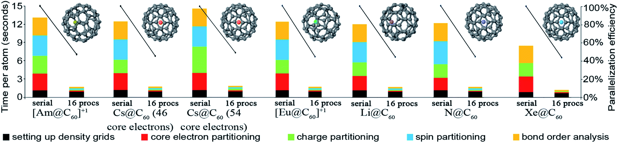 | ||
| Fig. 22 Parallelization timing and efficiency results for: [Am@C60]+1, Cs@C60 (46 frozen Cs core electrons), Cs@C60 (54 simulated frozen Cs core electrons), [Eu@C60]+1, Li@C60, N@C60, and Xe@C60. These calculations have 61 atoms per unit cell and were computed using PBE/planewave. | ||
To study the effect of constraint (11), the Cs@C60 was analyzed using both 46 and 54 simulated Cs frozen core electrons. When using 46 Cs frozen core electrons, the constraint (11) applied but was not binding, thus κCs = 0. When using 54 simulated Cs frozen core electrons, constraint (11) bound, thus κCs > 0. Because {κA} updating was required when using 54 simulated Cs frozen core electrons, the charge partitioning part of the computation was more expensive than for the 46 Cs frozen core electron calculation. In general, the time for core electron partitioning can be affected by the number of core electrons. The times required for all other parts of the calculation were not affected. This demonstrates changes in the number of frozen core electrons have only a small effect on the overall computational time and parallelization efficiency.
Table 14 shows the endohedral bond orders and NACs. Only Am+1, Cs, Eu+1, and Li form an ionic bond between the central atom and the carbon cage, while N and Xe show weak charge transfer. The largest X–C bond order was small (0.178 for Am+1). There was an overall trend of increasing SBO with increasing atomic number. This demonstrates that heavier atoms have a more diffuse electron cloud that overlaps more with the electron cloud of the C60 cage.
Every C atom in the C60 molecule is equivalent, being shared by two C6 rings and one C5 ring. There are two types of bonds: (a) a bond shared between a C6 and a C5 ring, and (b) a bond shared between two C6 rings. The C NAC in N@C60 was nearly zero (−0.007 to 0.003). The bond order type (a) in N@C60 was 1.12, while the bond order type (b) was 1.30. The SBO for each C atom in N@C60 was 3.93. This SBO is in line with the chemical expectation that each C atom shares four valence electrons.
4.9 The effects of large vacuum space in unit cell: water dimer
Some linearly scaling computational methods scale proportional to the number of atoms in the unit cell while others scale proportional to volume (or number of grid points) in the unit cell. To investigate this issue, we constructed a large periodic unit cell containing a water dimer surrounded by a large region of vacuum space. We used the equilibrium CCSD(T)/CBS water dimer geometry reported by Rezac et al.78 The water molecule has a nearly tetrahedral geometry, with hydrogens occupying two sites and lone pairs occupying the other two sites. A hydrogen bond keeps the dimer together connecting one hydrogen in one molecule to one oxygen lone pair in the other molecule.As shown in Fig. 23, the DDEC6 serial computation required ∼20 seconds per atom. The OpenMP code ran slightly faster on one processor than the serial (non-OpenMP) code. The parallelization efficiency dropped substantially when increasing the number of parallel processors. For 16 processors, the parallelization efficiency dropped to ∼11%. As shown in Fig. 23, this was because the time required for setting up density grids did not decrease significantly with increasing number of processors. This was because the input file reading was not parallelized. When the time required for setting up the density grids is omitted, parallelization efficiencies increase to ≥ ∼60%. Although one could potentially improve the parallelization efficiency of setting up the density grids by parallelizing the input file reading, we chose not to do so at this time to keep the code simpler. Parallel input file reading may pose challenges for code portability as well as exhibit different performance on different types of operating systems or machine architectures. Also, errors during input file reading caused by incorrect input files will be easier to analyze and fix if the input file reading is performed sequentially rather than in parallel.
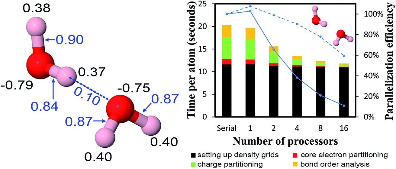 | ||
| Fig. 23 Left: NACs (black) and bond orders (blue) of water dimer. Right: Parallelization timing and efficiency results for water dimer (6 atoms per unit cell, PBE/planewave method). The solid blue line is the overall parallelization efficiency. The dashed blue line is the parallelization efficiency excluding setting up density grids. | ||
During core electron partitioning, charge partitioning, spin partitioning (for magnetic materials), and bond order analysis, the main loops run over atoms (or atom pairs in bond order analysis) and grid points within the cutoff radius of each atom. In this particular type of loop, the vacuum space far away from all atoms contributes to the memory required to store the big array, but not significantly to the computational time. Consequently, the time per atom required to perform core electron partitioning, charge partitioning, and bond order analysis was similar for the water dimer surrounded by a large vacuum space as for the other materials described above irrespective of whether they contained a vacuum region. This indicates that after setting up the density grids, the computational time scales proportional to the number of atoms (for a given grid spacing) rather than proportional to volume of the unit cell.
DDEC6 NACs and bond orders are also shown in Fig. 23. The H–O distances are 2.01 Å for the hydrogen bond and 0.96 Å for the covalent bond. The computed DDEC6 H–O bond orders are 0.84–0.90 for the covalent bond and 0.10 for the hydrogen bond. The computed NACs indicate that the H–O covalent bond in water is polar–covalent with electrons drawn from the hydrogen towards the oxygen. As discussed in our previous publication, the DDEC6 H2O NACs are in good agreement with common 3-site water models typically used in classical atomistic molecular dynamics and Monte Carlo simulations.18 (The similarity of DDEC NACs for bulk water to common three-site water models was first pointed out by Lee et al.35)
5. Conclusions
In this article, we studied efficient parallel computation of NACs, ASMs, and bond orders using the DDEC6 method. These calculations also included rapid computation of atomic dipoles and quadrupoles, electron cloud parameters, and r-cubed moments. r-Cubed moments are useful for computing atomic polarizabilities and dispersion coefficients.81,82 The DDEC6 method has the advantage of being the most accurate and broadly applicable APAM developed to date that partitions the material into overlapping atoms.17,18 We presented an efficient parallel implementation of the DDEC6 method using an OpenMP parallelized Fortran code. We described several components necessary to achieve an efficiently running code: (a) flow diagrams and modular design, (b) memory management, (c) computational cutoffs to achieve linear scaling, (d) efficient assignment of the computational work to parallel threads, (e) integration strategy, and (f) lookup tables to speed function evaluations.We summarized theory, flow diagrams, main features, and computational parameters for DDEC6 analysis. A key advantage is that the DDEC6 method has predictably rapid and robust convergence. DDEC6 charge partitioning requires seven charge partitioning steps, and this corresponds to solving a series of 14 Lagrangians in order. DDEC6 ASMs are computed using the DDEC spin partitioning algorithm of Manz and Sholl19 applied using the DDEC6 {ρA(A)}.17,18 These ASMs converge exponentially fast. The DDEC6 bond orders are computed using the recently developed comprehensive bond order equation.16 A key advantage of this method is that it can be applied to materials with no magnetism, collinear magnetism, or non-collinear magnetism. Another key advantage is that the method works efficiently for non-periodic materials and for materials with 1, 2, or 3 periodic directions.
We tested serial code and OpenMP parallelized code run on 1, 2, 4, 8, and 16 processors on a cache coherent node. We studied materials containing from one to 8748 atoms per unit cell. For each material, the memory required was nearly independent of the number of parallel threads. We developed an equation that can safely predict the required memory based on the system type (i.e., no magnetism, collinear magnetism, or non-collinear magnetism), the number of grid points in the unit cell, and the number of atoms in the unit cell. The required memory scales linearly with increasing system size. For serial mode, the computational time per atom ranged from ∼9 to 94 seconds. The parallelization efficiencies were typically >50%, indicating good performance. Even computations for the Ni metal containing a single atom per unit cell exhibited good parallelization efficiencies. Computations for a series of ice crystal unit cells containing 12, 96, 324, 768, 1500, 2592, 4116, 6144, and 8748 atoms showed the serial and parallel computational times scale linearly with increasing unit cell size, the parallelization efficiency is independent of the unit cell size, and the memory required scales linearly with the unit cell size. Both the required memory and computational time scaled linearly with increasing number of grid points.
There are several important components of memory management. First, the large arrays should be allocated as shared variables (not private variables) to avoid separate large array allocations for each parallel thread. Also, reductions should not be performed over the large arrays, because reductions require the temporary creation of a private copy of the array for each thread. Separate large array allocations for each parallel thread would cause the required memory to grow with addition of parallel threads, while using large shared arrays (not reduced over) causes the required memory to be approximately constant irrespective of the number of parallel threads. Second, the large arrays should be stored and accessed in cache friendly order to avoid false sharing. Specifically, a parallel thread should work on elements of the large array that do not invalidate the cache used by the other parallel threads, and a parallel thread should access the large array in cache line order. Third, the REDUCTION directives should be properly positioned to avoid performing the REDUCTION directive an unnecessary number of times. Fourth, the number of ATOMIC or CRITICAL directives should be minimized to avoid parallel threads waiting for each other. Fifth, the program should read the input information in chunks so that it does not overflow the read buffer size set by the operating system.
It is useful to make a few comments about the relationship between parallel threads and computing cores. Nearly all of the computations performed in this paper used a one-to-one ratio between parallel threads and computing cores. For comparison, we also performed computations in which there were two parallel threads per computing core (i.e., 32 threads on 16 cores). For two threads per core most parts of the computation ran about the same speed as one thread per core, but two threads per core ran slightly slower overall than one thread per core. We also performed parallelization tests with and without binding a particular thread to a particular computing core, but the differences in computational times were negligible.
One system exhibiting poor parallelization efficiencies (<50%) was the water–water dimer placed in a large unit cell. For this system, the parallelization efficiency was low owing to the substantial fraction of time required to read the input density grid files. For simplicity, we did not parallelize the input file reading. Thus, in cases where a small number of atoms are placed within a large unit cell containing a large proportion of vacuum space, the serial input file reading can become the rate-limiting part of the computation. The parallelization efficiency was >50% when recomputed excluding the time required to read and process the input files (i.e., set up the density grids). Since the time required to read and process the input files was 12 seconds per atom for this case, we do not believe this represents a serious limitation.
For calculations using density grids computed via planewave QC calculations, we investigated the effects of changing the number of k-points, the planewave cutoff energy, and the real-space grid spacing. The MAD and MADM were computed to quantify non-systematic and systematic errors, respectively, in the NAC, atomic dipole magnitude, max quadrupole eigenvalue, SBO, density tail exponent, and r-cubed moment. We propose appropriate choices for the number of k-points, the planewave cutoff energy, and the real-space grid spacing to simultaneously achieve low computational cost and high precision.
All of our results show the DDEC6 method is well-suited for use as a default APAM in QC programs. Specifically, we found the DDEC6 method can be written as a modular program, efficiently parallelized, and run with reasonable computational times and memory requirements. For systems with pre-computed electron and spin density grids, both the required computational time and memory scale linearly with increasing system size. This makes the DDEC6 method well-suited for studying both large and small systems. As demonstrated in our prior articles, the extremely broad applicability and high chemical accuracy of the DDEC6 method makes it the first AIM method suitable for use as a default APAM in QC programs.17,18 We hope these results will inspire QC program developers to interface the DDEC6 method with their QC programs.
When generating density grids from Gaussian basis set coefficients inputs, there are further opportunities for optimization. For this kind of calculation, the density grid generation (but not the input file reading) took up more computational time than the subsequent core electron partitioning, charge partitioning, spin partitioning, and bond order analysis. This suggests further opportunities for optimizing the integration grid strategy for Gaussian basis set coefficients inputs. Some strategies worth considering are atom-centered overlapping grids,31 atom-centered non-overlapping grids,32 and separable uniform grid averaging.79
Conflicts of interest
There are no conflicts of interest to declare.Acknowledgements
This project was funded in part by National Science Foundation (NSF) CAREER Award DMR-1555376. Supercomputing resources were provided by the Extreme Science and Engineering Discovery Environment (XSEDE).80 XSEDE is funded by NSF grant ACI-1053575. XSEDE project grant TG-CTS100027 provided allocations on the Trestles and Comet clusters at the SDSC and the Stampede 1 cluster at the TACC. The authors sincerely thank the technical support staff of XSEDE, TACC, and SDSC.References
- Q. Yang, D. Liu, C. Zhong and J.-R. Li, Chem. Rev., 2013, 113, 8261–8323 CrossRef CAS PubMed.
- I. Erucar, T. A. Manz and S. Keskin, Mol. Simul., 2014, 40, 557–570 CrossRef CAS.
- T. Murtola, A. Bunker, I. Vattulainen, M. Deserno and M. Karttunen, Phys. Chem. Chem. Phys., 2009, 11, 1869–1892 RSC.
- T. S. Gates, G. M. Odegard, S. J. V. Frankland and T. C. Clancy, Compos. Sci. Technol., 2005, 65, 2416–2434 CrossRef CAS.
- J. J. Spivey, K. S. Krishna, C. S. S. R. Kumar, K. M. Dooley, J. C. Flake, L. H. Haber, Y. Xu, M. J. Janik, S. B. Sinnott, Y. T. Cheng, T. Liang, D. S. Sholl, T. A. Manz, U. Diebold, G. S. Parkinson, D. A. Bruce and P. de Jongh, J. Phys. Chem. C, 2014, 118, 20043–20069 CAS.
- D. Nazarian, J. S. Camp and D. S. Sholl, Chem. Mater., 2016, 28, 785–793 CrossRef CAS.
- R. Salomon-Ferrer, D. A. Case and R. C. Walker, Wiley Interdiscip. Rev.: Comput. Mol. Sci., 2013, 3, 198–210 CrossRef CAS.
- S. Cardamone, T. J. Hughes and P. L. A. Popelier, Phys. Chem. Chem. Phys., 2014, 16, 10367–10387 RSC.
- D. J. Cole, J. Z. Vilseck, J. Tirado-Rives, M. C. Payne and W. L. Jorgensen, J. Chem. Theory Comput., 2016, 12, 2312–2323 CrossRef CAS PubMed.
- J. M. Wang, P. Cieplak, J. Li, T. J. Hou, R. Luo and Y. Duan, J. Phys. Chem. B, 2011, 115, 3091–3099 CrossRef CAS PubMed.
- J. M. Wang, P. Cieplak, J. Li, J. Wang, Q. Cai, M. J. Hsieh, H. X. Lei, R. Luo and Y. Duan, J. Phys. Chem. B, 2011, 115, 3100–3111 CrossRef CAS PubMed.
- P. Maxwell, N. di Pasquale, S. Cardamone and P. L. A. Popelier, Theor. Chem. Acc., 2016, 135, 195 CrossRef.
- R. S. Mulliken, J. Chem. Phys., 1955, 23, 1833–1840 CrossRef CAS.
- G. Bruhn, E. R. Davidson, I. Mayer and A. E. Clark, Int. J. Quantum Chem., 2006, 106, 2065–2072 CrossRef CAS.
- J. Cioslowski, J. Am. Chem. Soc., 1989, 111, 8333–8336 CrossRef CAS.
- T. A. Manz, RSC Adv., 2017, 7, 45552–45581 RSC.
- T. A. Manz and N. Gabaldon Limas, RSC Adv., 2016, 6, 47771–47801 RSC.
- N. Gabaldon Limas and T. A. Manz, RSC Adv., 2016, 6, 45727–45747 RSC.
- T. A. Manz and D. S. Sholl, J. Chem. Theory Comput., 2011, 7, 4146–4164 CrossRef CAS PubMed.
- M. Metcalf, J. Reid and M. Cohen, Modern Fortran Explained, Oxford University Press, Oxford, United Kingdom, 2011 Search PubMed.
- J. C. Adams, W. S. Brainerd, R. A. Hendrickson, J. T. Maine and B. T. Smith, The Fortran 2003 Handbook, Springer, New York, 2009 Search PubMed.
- R. M. Hanson, J. Appl. Crystallogr., 2010, 43, 1250–1260 CAS.
- Jmol: an open-source Java viewer for chemical structures in 3D, http://www.jmol.org, accessed: July 2015.
- G. Kresse and J. Hafner, Phys. Rev. B: Condens. Matter Mater. Phys., 1993, 47, 558–561 CrossRef CAS.
- G. Kresse and J. Hafner, Phys. Rev. B: Condens. Matter Mater. Phys., 1994, 49, 14251–14269 CrossRef CAS.
- J. Hafner, J. Comput. Chem., 2008, 29, 2044–2078 CrossRef CAS PubMed.
- G. Kresse and J. Furthmuller, Phys. Rev. B: Condens. Matter Mater. Phys., 1996, 54, 11169–11186 CrossRef CAS.
- T. A. Manz and D. S. Sholl, J. Chem. Theory Comput., 2012, 8, 2844–2867 CrossRef CAS PubMed.
- T. A. Manz and D. S. Sholl, J. Chem. Theory Comput., 2010, 6, 2455–2468 CrossRef CAS PubMed.
- T. A. Manz, J. Comput. Chem., 2013, 34, 418–421 CrossRef CAS PubMed.
- A. D. Becke, J. Chem. Phys., 1988, 88, 2547–2553 CrossRef CAS.
- G. te Velde and E. J. Baerends, J. Comput. Phys., 1992, 99, 84–98 CrossRef CAS.
- E. D. Stevens, J. Rys and P. Coppens, J. Am. Chem. Soc., 1978, 100, 2324–2328 CrossRef CAS.
- J. L. Staudenmann, P. Coppens and J. Muller, Solid State Commun., 1976, 19, 29–33 CrossRef CAS.
- L. P. Lee, D. J. Cole, C.-K. Skylaris, W. L. Jorgensen and M. C. Payne, J. Chem. Theory Comput., 2013, 9, 2981–2991 CrossRef CAS PubMed.
- F. L. Hirshfeld, Theor. Chim. Acta, 1977, 44, 129–138 CrossRef CAS.
- P. Bultinck, C. Van Alsenoy, P. W. Ayers and R. Carbo-Dorca, J. Chem. Phys., 2007, 126, 144111 CrossRef PubMed.
- T. C. Lillestolen and R. J. Wheatley, Chem. Commun., 2008, 5909–5911 RSC.
- M. Hermanns, Parallel Programming in Fortran 95 using OpenMP, Madrid, Spain, 2002, pp. 1–71, http://www.openmp.org/wp-content/uploads/F95_OpenMPv1_v2.pdf, accessed: May 2017 Search PubMed.
- B. Chapman, G. Jost and A. R. van der Pas, Using OpenMP, The MIT Press, Cambridge, Massachusetts, 2008 Search PubMed.
- L. P. Lee, N. G. Limas, D. J. Cole, M. C. Payne, C. K. Skylaris and T. A. Manz, J. Chem. Theory Comput., 2014, 10, 5377–5390 CrossRef CAS PubMed.
- C. K. Skylaris, P. D. Haynes, A. A. Mostofi and M. C. Payne, J. Chem. Phys., 2005, 122, 084119 CrossRef PubMed.
- K. A. Wilkinson, N. D. M. Hine and C. K. Skylaris, J. Chem. Theory Comput., 2014, 10, 4782–4794 CrossRef CAS PubMed.
- M. J. Frisch, G. W. Trucks, H. B. Schlegel, G. E. Scuseria, M. A. Robb, J. R. Cheeseman, G. Scalmani, V. Barone, B. Mennucci, G. A. Petersson, H. Nakatsuji, M. Caricato, X. Li, H. P. Hratchian, A. F. Izmaylov, J. Bloino, G. Zheng, J. L. Sonnenberg, M. Hada, M. Ehara, K. Toyota, R. Fukuda, J. Hasegawa, M. Ishida, T. Nakajima, Y. Honda, O. Kitao, H. Nakai, T. Vreven, J. A. J. Montgomery, J. E. Peralta, F. Ogliaro, M. Bearpark, J. J. Heyd, E. Brothers, K. N. Kudin, V. N. Staroverov, T. Keith, R. Kobayashi, J. Normand, K. Raghavachari, A. Rendell, J. C. Burant, S. S. Iyengar, J. Tomasi, M. Cossi, N. Rega, J. M. Millam, M. Klene, J. E. Knox, J. B. Cross, V. Bakken, C. Adamo, J. Jaramillo, R. Gomperts, R. E. Stratmann, O. Yazyev, A. J. Austin, R. Cammi, C. Pomelli, J. W. Ochterski, R. L. Martin, K. Morokuma, V. G. Zakrzewski, G. A. Voth, P. Salvador, J. J. Dannenberg, S. Dapprich, A. D. Daniels, O. Farkas, J. B. Foresman, J. V. Ortiz, J. Cioslowski and D. J. Fox, Gaussian 09, Gaussian, Inc., Wallingford, CT, 2010 Search PubMed.
- I. M. L. Billas, A. Chatelain and W. A. de Heer, Science, 1994, 265, 1682–1684 CAS.
- S. Arai, T. Chatake, T. Ohhara, K. Kurihara, I. Tanaka, N. Suzuki, Z. Fujimoto, H. Mizuno and N. Niimura, Nucleic Acids Res., 2005, 33, 3017–3024 CrossRef CAS PubMed.
- N. Foloppe and A. D. MacKerell, J. Comput. Chem., 2000, 21, 86–104 CrossRef CAS.
- W. D. Cornell, P. Cieplak, C. I. Bayly, I. R. Gould, K. M. Merz, D. M. Ferguson, D. C. Spellmeyer, T. Fox, J. W. Caldwell and P. A. Kollman, J. Am. Chem. Soc., 1995, 117, 5179–5197 CrossRef CAS.
- J. D. Watson and F. H. C. Crick, Nature, 1953, 171, 737–738 CrossRef CAS PubMed.
- J. Sponer, J. Leszczynski and P. Hobza, Biopolymers, 2001, 61, 3–31 CrossRef CAS PubMed.
- T. van der Wijst, C. F. Guerra, M. Swart and F. M. Bickelhaupt, Chem. Phys. Lett., 2006, 426, 415–421 CrossRef CAS.
- T. Lis, Acta Crystallogr., Sect. B: Struct. Crystallogr. Cryst. Chem., 1980, 36, 2042–2046 Search PubMed.
- M. N. Leuenberger and D. Loss, Nature, 2001, 410, 789–793 CrossRef CAS PubMed.
- K. M. Mertes, Y. Suzuki, M. P. Sarachik, Y. Myasoedov, H. Shtrikman, E. Zeldov, E. M. Rumberger, D. N. Hendrickson and G. Christou, Solid State Commun., 2003, 127, 131–139 CrossRef CAS.
- J. Callaway, Quantum Theory of the Solid State, Academic Press, San Diego, CA, 1991, pp. 1–120 Search PubMed.
- A. A. Mostofi, C. K. Skylaris, P. D. Haynes and M. C. Payne, Comput. Phys. Commun., 2002, 147, 788–802 CrossRef CAS.
- A. A. Mostofi, P. D. Haynes, C. K. Skylaris and M. C. Payne, J. Chem. Phys., 2003, 119, 8842–8848 CrossRef CAS.
- H. J. Monkhorst and J. D. Pack, Phys. Rev. B: Solid State, 1976, 13, 5188–5192 CrossRef.
- P. E. Blochl, Phys. Rev. B: Condens. Matter Mater. Phys., 1994, 50, 17953–17979 CrossRef.
- G. Kresse and D. Joubert, Phys. Rev. B: Condens. Matter Mater. Phys., 1999, 59, 1758–1775 CrossRef CAS.
- P. L. Butzer, M. M. Dodson, P. J. S. G. Ferreira, J. R. Higgins, O. Lange and P. Seidler, Signal Process., 2010, 90, 1436–1455 CrossRef.
- C. E. Shannon, Proc. IEEE, 1998, 86, 447–457 CrossRef.
- H. D. Luke, IEEE Commun. Mag., 1999, 37, 106–108 CrossRef.
- H. Nyquist, Proc. IEEE, 2002, 90, 280–305 CrossRef.
- G. Kresse, M. Marsman and J. Furthmüller, The VASP Guide, http://cms.mpi.univie.ac.at/vasp/vasp/vasp.html, accessed: May 2017 Search PubMed.
- W. Kohn and L. J. Sham, Phys. Rev., 1965, 140, 1133–1138 CrossRef.
- S. L. Dudarev, G. A. Botton, S. Y. Savrasov, C. J. Humphreys and A. P. Sutton, Phys. Rev. B: Condens. Matter Mater. Phys., 1998, 57, 1505–1509 CrossRef CAS.
- S. Grimme, A. Hansen, J. G. Brandenburg and C. Bannwarth, Chem. Rev., 2016, 116, 5105–5154 CrossRef CAS PubMed.
- A. D. Becke, J. Chem. Phys., 1993, 98, 5648–5652 CrossRef CAS.
- P. J. Stephens, F. J. Devlin, C. F. Chabalowski and M. J. Frisch, J. Phys. Chem., 1994, 98, 11623–11627 CrossRef CAS.
- J. P. Perdew, J. A. Chevary, S. H. Vosko, K. A. Jackson, M. R. Pederson, D. J. Singh and C. Fiolhais, Phys. Rev. B: Condens. Matter Mater. Phys., 1992, 46, 6671–6687 CrossRef CAS.
- G. E. Scuseria and H. F. Schaefer, J. Chem. Phys., 1989, 90, 3700–3703 CrossRef CAS.
- N. Yamamoto, T. Vreven, M. A. Robb, M. J. Frisch and H. B. Schlegel, Chem. Phys. Lett., 1996, 250, 373–378 CrossRef CAS.
- H. Nakatsuji and K. Hirao, J. Chem. Phys., 1978, 68, 2053–2065 CrossRef CAS.
- H. Nakatsuji, Chem. Phys. Lett., 1979, 67, 334–342 CrossRef CAS.
- R. A. Kendall, T. H. Dunning and R. J. Harrison, J. Chem. Phys., 1992, 96, 6796–6806 CrossRef CAS.
- L. Pauling, J. Am. Chem. Soc., 1947, 69, 542–553 CrossRef CAS.
- J. Rezac, K. E. Riley and P. Hobza, J. Chem. Theory Comput., 2011, 7, 2427–2438 CrossRef CAS PubMed.
- J. P. Ritchie and S. M. Bachrach, J. Comput. Chem., 1987, 8, 499–509 CrossRef CAS.
- J. Towns, T. Cockerill, M. Dahan, I. Foster, K. Gaither, A. Grimshaw, V. Hazlewood, S. Lathrop, D. Lifka, G. D. Peterson, R. Roskies, J. R. Scott and N. Wilkins-Diehr, Comput. Sci. Eng., 2014, 16, 62–74 CrossRef.
- A. Tkatchenko and M. Scheffler, Phys. Rev. Lett., 2009, 102, 073005 CrossRef PubMed.
- A. Tkatchenko, R. A. DiStasio, R. Car and M. Scheffler, Phys. Rev. Lett., 2012, 108, 236402 CrossRef PubMed.
Footnote |
| † Electronic supplementary information (ESI) available: ESI documentation includes a pdf file containing: the 14 charge partitioning Lagrangians (S1); spin partitioning Lagrangian and flow diagram (S2); equations for bond order analysis (S3); algorithm for total electron density grid correction (S4); table and description listing big arrays and in which modules they are allocated and deallocated (S5); table and description of computational parameters (S6); description of how to use the enclosed reshaping sub routines (S7); and description of how to use the enclosed spin functions (S8). Additionally ESI includes a zip format archive containing: the system geometries; Jmol readable xyz files containing DDEC6 NACs, atomic multipoles, electron cloud parameters, ASMs, SBOs, and r-cubed moments; DDEC6 bond orders and overlap populations; a Fortran module containing reshaping subroutines; and a Fortran module containing spin functions. See DOI: 10.1039/c7ra11829e |
| This journal is © The Royal Society of Chemistry 2018 |