 Open Access Article
Creative Commons Attribution 3.0 Unported Licence
Preparation of functionalized zirconium phosphate and its effect on the flame retardancy of silicone rubber†
Yajun Zhang,
Xingrong Zeng *,
Xuejun Lai* and
Hongqiang Li
College of Materials Science and Engineering, South China University of Technology, No 381, Wushan Road, Tianhe District, Guangzhou 510640, China. E-mail: psxrzeng@gmail.com; msxjlai@scut.edu.cn; Fax: +86-20-87114248; Tel: +86-20-87114248 Tel: +86-20-22236629
First published on 2nd January 2018
Abstract
How to effectively enhance the flame retardancy of silicone rubber is an important but challenging task. In this contribution, functionalized zirconium phosphate (F-ZrP) was prepared by the intercalation of 1,2,2,6,6-pentamethyl-4-(vinyldiethoxysiloxy) piperidine (PMVP) into α-zirconium phosphate (α-ZrP), and was employed to enhance the flame retardancy of addition-cured liquid silicone rubber (ALSR). Results showed that ALSR had no rating in the UL-94 test with the LOI value of 28.0%. F-ZrP could significantly improve the flame retardancy of ALSR. When only 4.0 phr F-ZrP was added, the limiting oxygen index (LOI) value reached 31.0% and the vertical burning test (UL-94) passed the V-0 rating. Moreover, compared to ALSR, the peak heat release rate (PHRR) and the total heat release (THR) of ALSR/F-ZrP decreased by 54.2% and 47.5%, respectively. The probable flame retardant mechanism of F-ZrP was mainly attributed to the synergism of the catalyzing carbonization and free-radical quenching effects. On the one hand, PMVP suppressed the thermal degradation of silicone chains in the condensed phase and quenched the active free-radicals in the gas phase by generating nitroxyl radicals. On the other hand, ZrP promoted silicone chain self-crosslinking and the formation of the graphitized carbons, resulting in the formation of the compact and thermostable ceramic layer, which was good barrier to protect the underlying matrix and inhibit the exchange of degradation products and oxygen.
1. Introduction
Silicone rubber (SR) is one of the most important high-performance polymers due to its hydrophobicity, chemical resistance, high temperature resistance and excellent electrical properties.1,2 However, the flammability of SR severely limits its further application in many fields that require flame retardancy, such as aerospace, nuclear power and electric transmission.3,4 Among the halogen-free flame retardants for SR, metal hydroxides are the most widely used because they are cheap and environmentally-friendly.5 Unfortunately, the flame retardancy efficiency of metal hydroxides is very low and a large usage amount (>50 wt%) is necessary to make SR achieve desirable flame retardancy. In this case, the mechanical properties of SR are inevitably seriously damaged. Therefore, it is imperative to develop a more efficient flame retardant to enhance the flame retardancy of SR.Layered nanomaterials have attracted much attention as a new generation of flame retardants, because they can endow polymers with excellent mechanical, thermal, barrier properties and flame retardancy by a small amount.6–8 For SR/layered nanocomposites, most studies were focused on the layered silicates (like montmorillonite) and layered double hydroxides.9–11 In fact, α-zirconium phosphate is also a typical layered nanomaterial which consists of zirconium atoms in a plane and phosphate groups bonded to a different Zr atom above and below the plane.12 α-Zirconium phosphate (α-ZrP) exhibits some advantages over montmorillonite, including higher purity and ease of intercalation and/or exfoliation.13,14 Moreover, benefiting from its elemental composition, α-ZrP also shows the characteristic of the solid acid catalyst,15,16 which can catalyze the dehydrogenation of polymers and promote the charring of polymers.17 These characteristics suggest that α-ZrP has the great potential in the application of the flame retardant SR. However, it is a great challenge to make zirconium phosphate dispersed uniformly in SR, because α-ZrP is commonly organically modified by an ammonium salt bearing long alkyl chains18 which has poor compatibility with SR, thus it is not conducive for the polysiloxane molecules to further intercalate into α-ZrP.
Hindered amine is a family member of piperidine derivatives and it has been used as a UV stabilizer for a long time. Recently, many studies show hindered amine possesses excellent flame retardancy, because it degrades thermally to generate efficient and regenerable free radical scavengers which interrupt and suppress the free radical combustion progress of polymers.19,20 Moreover, hindered amine has the structure of tertiary amine in the heterocyclic ring, suggesting it can act as a surfactant for α-ZrP. Thus, if α-ZrP is functionalized with hindered amine, there would be a strong possibility to greatly improve the flame retardancy of SR.
In this work, in order to enhance the compatibility between ZrP and SR, a novel hindered amine containing silane and carbon carbon double bond, 1,2,2,6,6-pentamethyl-4-(vinyldiethoxysiloxy)-piperidine (PMVP) was synthesized through the transesterification of vinyltriethoxysilane with 1,2,2,6,6-pentamethyl-4-piperidinol (PMPO). Then PMVP was employed to prepare the functionalized zirconium phosphate (F-ZrP) via the intercalation reaction. The structure and morphology of F-ZrP were characterized by Fourier transform infrared spectroscopy (FTIR), X-ray diffraction (XRD) and transmission electron microscopy (TEM). F-ZrP was used to flame-retard addition-cure liquid silicone rubber (ALSR). The flame-retardant properties of ALSR/F-ZrP nanocomposite were systematically studied by the limiting oxygen index (LOI), UL-94 and cone calorimetry measurements. This investigation would develop a new and efficient strategy to prepare the high-performance silicone rubber.
2. Experimental
2.1 Materials
α-ZrP was synthesized according to Sun et al.21 vinyltriethoxysilane (VTES) was provided by Qufu Chenguang Chemical Co., Ltd., China. 1,2,2,6,6-Pentamethyl-4-piperidinol (PMPO) was supplied by Energy Chemical Co., Ltd., China. Tetrabutyl titanate (TBT) was purchased from Tianjin Fuchen Chemical Reagent Factory, China. Vinyl-terminated poly(dimethylsiloxane) (VPDMS, viscosity was 20![[thin space (1/6-em)]](https://www.rsc.org/images/entities/char_2009.gif) 000 mPa s and vinyl content was 0.12 wt%), ploy(hydromethylsiloxane) (PHMS, viscosity was 160 mPa s and hydride content was 0.70 wt%), platinum(0)-1,3-divinyl-1,1,3,3-tetramethydisiloxane complex (Karstedt's catalyst, 3000 ppm) and 1-ethynylcyclohexanol were supplied by Guangzhou Tinci Silicon Technology Co., Ltd., China. Fumed silica (M-5) was purchased from Cabot Co., Ltd., USA.
000 mPa s and vinyl content was 0.12 wt%), ploy(hydromethylsiloxane) (PHMS, viscosity was 160 mPa s and hydride content was 0.70 wt%), platinum(0)-1,3-divinyl-1,1,3,3-tetramethydisiloxane complex (Karstedt's catalyst, 3000 ppm) and 1-ethynylcyclohexanol were supplied by Guangzhou Tinci Silicon Technology Co., Ltd., China. Fumed silica (M-5) was purchased from Cabot Co., Ltd., USA.
2.2 Preparation of functionalized zirconium phosphate
PMVP was prepared as illustrated in Fig. 1a. In a 500 mL four-neck flask, 19.0 g VTES (0.1 mol) was added to a solution composed of 0.2 g TBT and 200 mL toluene with stirring. The reaction system was heated to 70 °C, and 17.1 g PMPO (0.1 mol) was added dropwise with vigorous stirring. Afterwards, the reaction was kept at 70 °C for 2 h. Then, the reaction was maintained for another 2 h under the reduced pressure and the toluene was removed to obtain PMVP. The chemical structure of PMVP was determined by 1H NMR (300 MHz, CDCl3, δ): 1.1–1.3(C–CH3, 18H), 1.50–1.83(C–CH2, 4H), 2.24(N–CH3, 3H), 2.35(O–CH–, 1H), 3.83(O–CH2–, 4H), 5.87–6.15(–CH![[double bond, length as m-dash]](https://www.rsc.org/images/entities/char_e001.gif) CH2, 3H).
CH2, 3H).
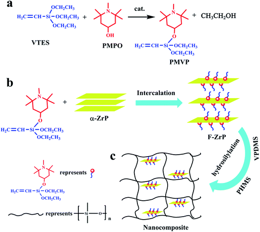 | ||
| Fig. 1 Schematic illustration for the preparation routes: (a) PMPV, (b) F-ZrP and (c) ALSR/F-ZrP nanocomposite. | ||
2.8 g α-ZrP (0.01 mol) was placed in a three-neck flask and dispersed by 280 mL toluene, then 6.3 g PMVP (0.02 mol) was added dropwise into the suspension followed by 10 min of ultrasonication. The mixture was stirred for another 7 h at 30 °C. Finally, the product was washed three times with toluene and ethanol respectively, filtered and dried in an oven at 65 °C for 12 h. The functionalized ZrP (F-ZrP) was obtained and the intercalation reaction is illustrated in Fig. 1b. The chemical formula of F-ZrP was determined by the EDS: Zr(HPO4)2(PMVP)0.79.
2.3 Preparation of the flame-retardant ALSR composites
F-ZrP was suspended in toluene through ultrasonication for 0.5 h. Then, 100 phr VPDMS was added into the suspension with vigorous stirring at 30 °C for 5 h. Afterwards, the toluene was removed from the VPDMS/F-ZrP mixture. Subsequently, 40 phr fume silica, 1.5 phr PHMS, 0.5 phr Karstedt's catalyst and 0.06 phr 1-ethynylcyclohexanol were mixed uniformly with the VPDMS/F-ZrP mixture by a kneader reactor (SH-5, RuGao ShengTeng Kneading Machinery Manufacturing Co., Ltd., China). Finally, the mixture was vulcanized at 120 °C for 10 min under 8 MPa by a press vulcanizer (XQLB-350 × 350, Shanghai Rubber Machinery Works No. 1 Co., Ltd., China) to obtain ALSR/F-ZrP nanocomposite. For comparision, ALSR samples with 4 phr α-ZrP and 4 phr PMVP were also obtained by the same method, denoted as ALSR/α-ZrP and ALSR/PMVP. The preparation of ALSR/F-ZrP nanocomposite is illustrated in Fig. 1c and the formulas of ALSR and its composites are presented in Table 1.| Sample | VPDMSa (phr) | α-ZrP (phr) | PMVP (phr) | F-ZrP (phr) |
|---|---|---|---|---|
| a The other ingredients of ALSR samples were fixed as: 40 phr (parts per 100 parts of VPDMS) of silica, 1.5 phr PHMS, 0.5 phr Karstedt's catalyst and 0.06 phr 1-ethynylcyclohexanol. | ||||
| ALSR | 100 | 0 | 0 | 0 |
| ALSR/α-ZrP | 100 | 4.0 | 0 | 0 |
| ALSR/PMVP | 100 | 0 | 4.0 | 0 |
| ALSR/F-ZrP-1 | 100 | 0 | 0 | 1 |
| ALSR/F-ZrP-2 | 100 | 0 | 0 | 2 |
| ALSR/F-ZrP-3 | 100 | 0 | 0 | 3 |
| ALSR/F-ZrP-4 | 100 | 0 | 0 | 4 |
2.4 Characterization
![[thin space (1/6-em)]](https://www.rsc.org/images/entities/char_2009.gif) sin
sin![[thin space (1/6-em)]](https://www.rsc.org/images/entities/char_2009.gif) θ = nλ, where d was the crystalline interplanar spacing, θ was the angle between the incident X-ray and the corresponding crystal surface, λ was the wavelength of X-ray and n was the diffraction series.
θ = nλ, where d was the crystalline interplanar spacing, θ was the angle between the incident X-ray and the corresponding crystal surface, λ was the wavelength of X-ray and n was the diffraction series.| Theat-resistance index = 0.49 × [T5% + 0.6 × (T30% − T5%)] | (1) |
3. Results and discussion
3.1 Characterization of F-ZrP
Fig. 2a shows the XRD patterns of α-ZrP and F-ZrP. As can be seen, the typical diffraction peaks at 2θ = 11.6, 19.8 and 25.0° correspond to the primary diffraction of (002), (110) and (112) planes of α-ZrP, respectively.23 The interlayer distance of (002) plane was 0.76 nm, which was estimated from Bragg's law.13 After α-ZrP was functionalized by PMVP, the diffraction peak of (002) plane was shifted to a low position (2θ = 5.3°), indicating an increase in the interlayer spacing to 1.66 nm.24 The increase of the interlayer spacing was beneficial to the intercalation of silicone chains into α-ZrP, and improved the dispersion of α-ZrP in SR.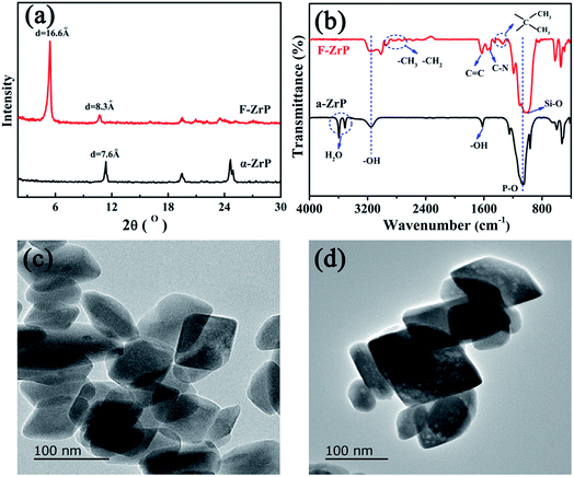 | ||
| Fig. 2 XRD patterns (a) and FTIR spectra (b) of α-ZrP and F-ZrP, and TEM images of α-ZrP (c) and F-ZrP (d). | ||
The FTIR spectra of α-ZrP and F-ZrP are presented in Fig. 2b. For α-ZrP, the absorption peaks at 3593 and 3510 cm−1 were attributed to the asymmetric stretching vibration of O–H in water molecules.25 The band around 3157 cm−1 was assigned to the stretching vibration of O–H in POH, while the deformation peak was located at 1618 cm−1.26 Compared with α-ZrP, there were some new absorbance peaks in the spectrum of F-ZrP. The absorption peaks at 2970 and 2925 cm−1 were assigned to –CH3 and –CH2, and the absorption peak at 1680 cm−1 was from C![[double bond, length as m-dash]](https://www.rsc.org/images/entities/char_e001.gif) C stretching vibration. The characteristic band of C–N appeared at 1530 and 1510 cm−1, while the deformation vibration of C–C in the methyl attached to the heterocyclic ring was observed at 1374 and 1342 cm−1.27 The strong absorption band around 1033 cm−1 became broader due to the overlap of P–O and Si–O.
C stretching vibration. The characteristic band of C–N appeared at 1530 and 1510 cm−1, while the deformation vibration of C–C in the methyl attached to the heterocyclic ring was observed at 1374 and 1342 cm−1.27 The strong absorption band around 1033 cm−1 became broader due to the overlap of P–O and Si–O.
In order to confirm whether the laminate structure of α-ZrP was destroyed after functionalized by PMVP, the morphology of α-ZrP and F-ZrP was observed by TEM. The results were shown in Fig. 2c and d. As can be seen, α-ZrP exhibited a typically smooth layered structure and packed tightly.28 After ZrP was functionalized by PMVP, the particle shape was not affected and was nearly identical to that of α-ZrP. Combining FTIR, XRD and TEM results, it revealed that PMVP was successfully intercalated into α-ZrP.
3.2 Morphology of the ALSR/F-ZrP nanocomposite
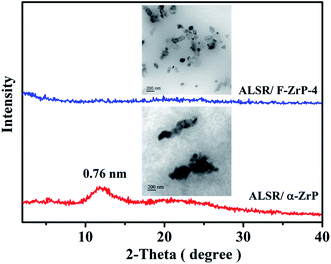
The homogeneous dispersion of nano flame retardants was the key factor affected its flame-retardant efficiency,29 thus it is necessary to study the dispersion of F-ZrP in ALSR. Fig. 3 shows the XRD patterns and TEM images of ALSR/α-ZrP and ALSR/F-ZrP-4. As seen from Fig. 3, for ALSR/α-ZrP composite, the main characteristic peak of α-ZrP remained at 11.6°, indicating that α-ZrP still existed with a structure of stack in ALSR. However, the characteristic peak of α-ZrP disappeared in the XRD pattern of ALSR/F-ZrP-4, revealing that F-ZrP nanosheets were well exfoliated in ALSR.The TEM images further confirmed the dispersion of α-ZrP and F-ZrP in ALSR. As can be seen, α-ZrP aggregated very seriously and dispersed poorly in ALSR due to the strong polarity. F-ZrP presented thin flakes and dispersed well in the matrix. PMVP had the silane structure and vinyl group, of which silane structure enhanced the compatibility between F-ZrP and silicone rubber, and vinyl group could link to silicone chains by the hydrosilylation reaction, which improved the interfacial interactions between F-ZrP and silicone rubber. Combining TEM and XRD results, it can be concluded that F-ZrP was exfoliated to thin flaked and dispersed well in ALSR.
3.3 Thermal stability of ALSR and its composites
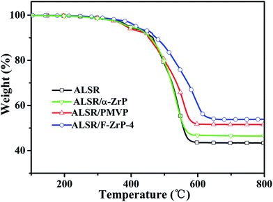
The TGA curves of ALSR, ALSR/PMVP, ALSR/α-ZrP and ALSR/F-ZrP-4 are presented in Fig. 4, and the corresponding characteristic data are summarized in Table 2. As can be seen, T5% and Theat-resistance index of ALSR/α-ZrP were almost the same to those of ALSR, but the residue at 800 °C increased from 43.3 wt% to 46.4 wt% due to the catalyzing carbonization effect of ZrP itself.15 Compared with ALSR, the T5% of ALSR/PMVP decreased from 394 °C to 386 °C due to the poor thermoxidation stability of PMVP. However, the Theat-resistance index of ALSR/PMVP increased from 231 °C to 233 °C and the residue at 800 °C increased from 43.3 wt% to 51.4 wt%. The reason might be that in the air, PMVP was oxidized easily to generate the efficient and regenerable free-radical scavengers – nitroxyl radicals,19 which could restrain the free-radical chemical reactions during the thermal degradation of ALSR. For ALSR/F-ZrP-4, the T5% increased by 21 °C compared with ALSR, due to the barrier effect of ZrP nanoplatelets, which delayed the oxidative degradation of silicone chains and PMVP. Moreover, Theat-resistance index and the residue at 800 °C also significantly increased. The results revealed that F-ZrP could greatly improve the thermal stability of ALSR, which was attributed to the synergism of PMVP and nano ZrP.| Sample | T5% (°C) | T30% (°C) | Theat-resistance index* (°C) | Residue at 800 °C (wt%) |
|---|---|---|---|---|
| ALSR | 394 | 522 | 231 | 43.3 |
| ALSR/α-ZrP | 392 | 521 | 230 | 46.4 |
| ALSR/PMVP | 386 | 536 | 233 | 51.4 |
| ALSR/F-ZrP-4 | 415 | 570 | 249 | 53.8 |
3.4 The flame retardancy and mechanical properties of ALSR and its composites
Table 3 shows the flame retardancy of ALSR and its composites. As can be seen, ALSR had no rating in the UL-94 test with the LOI value of 28.0%. When incorporating 4.0 phr of α-ZrP or PMVP, the LOI of the composites increased to 28.3% and 28.9% respectively, but they still classed no rating in the UL-94 test. However, F-ZrP could significantly improve the flame retardancy of ALSR. When the F-ZrP content was 2 phr, the LOI value of ALSR increased to 29.5% and it was self-extinguished in the UL-94 test. When the F-ZrP content was 4 phr, the nanocomposite reached the UL-94 V-0 rating and its LOI value increased to 31.0%.| Sample | LOI (%) | UL-94 | Self-extinguishing |
|---|---|---|---|
| a NR represents no rating. | |||
| ALSR | 28.0 ± 0.1 | NR | No |
| ALSR/α-ZrP | 28.3 ± 0.1 | NR | No |
| ALSR/PMVP | 28.9 ± 0.2 | NR | Yes |
| ALSR/F-ZrP-1 | 28.5 ± 0.1 | NR | No |
| ALSR/F-ZrP-2 | 29.5 ± 0.1 | NR | Yes |
| ALSR/F-ZrP-3 | 30.0 ± 0.2 | V-1 | Yes |
| ALSR/F-ZrP-4 | 31.0 ± 0.1 | V-0 | Yes |
Table S2† shows the mechanical properties of ALSR and its composites. As seen from Table S2,† compared to ALSR, the tensile strength and tear strength of ALSR/α-ZrP decreased slight. When 4 phr PMVP was added, the tensile strength of ALSR increased from 7.62 MPa to 7.98 MPa and the tear strength of ALSR increased from 20.6 kN m−1 to 23.9 kN m−1. PMVP had vinyl group which could link to silicone chains by the hydrosilylation reaction, and the nitrogen atoms in PMVP can form the strong hydrogen-bonds with the hydroxyl groups on the surface of SiO2, thus PMVP enhanced the interfacial interactions between silicone chains and SiO2, resulting in the increase of mechanical properties of ALSR. F-ZrP could effectively improve the mechanical properties of ALSR. When the content of F-ZrP was 4 phr, the tensile strength of ALSR increased from 7.62 MPa to 8.35 MPa, and the tear strength of ALSR increased from 20.6 kN m−1 to 26.0 kN m−1. The reason might be attributed to the improved interfacial interactions and dispersion of ZrP nano platelets in ALSR.
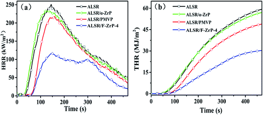
The cone calorimeter (CC) is a useful bench-scale for testing flammability properties of materials in real fire condition.30 In order to detailedly study the effect of F-ZrP on the flame retardancy of ALSR, the burning behavior of ALSR, ALSR/PMVP, ALSR/α-ZrP and ALSR/F-ZrP-4 was characterized by CC test. Fig. 5 shows the HRR and THR curves of ALSR, ALSR/PMVP, ALSR/α-ZrP and ALSR/F-ZrP-4, and some important parameters were summarized in Table 4. From Fig. 5 and Table 4, it can be observed that ALSR without additives was ignited soon (tign = 16 s) and burned rapidly. At 143 s, HRR reached peak value which was 251 kW m−2. When α-ZrP was added, the tign and tPHRR of ALSR/α-ZrP were reduced slightly, but the PHRR decreased from 251 kW m−2 to 232 kW m−2, compared with ALSR. This was because α-ZrP catalyzed silicone chains self-crosslinking to form a protection layer, accompanied by CH4 and the release of CH4 led to the decrease of the tign and tPHRR. However, the flame retardant efficiency of ALSR/α-ZrP was very low due to the poor dispersion of α-ZrP. When PMVP was individually introduced to ALSR, the tign and tPHRR of ALSR/PMVP was prolonged to 35 s and 159 s, respectively. Meanwhile, the PHRR value decreased from 251 kW m−2 to 217 kW m−2 and the THR value decreased from 59 MJ m−2 to 40 MJ m−2, compared with ALSR. During the combustion, PMVP degraded thermally to generate the nitroxyl radicals, which not only suppressed the degradation of ALSR in the condensed phase to reduce the generation of combustile gas, but also impeded the chain reactions of combustion in the gas phase.19,20 When F-ZrP was added, the tign of ALSR/F-ZrP-4 was 42 s, prolonged by 7 s compared with ALSR/PMVP and 26 s comapred with ALSR. The results indicated that on the one hand, ZrP nanoplatelets delayed the release of combustile gas by the barrier effect. On the other hand, PMVP in the interlayer of ZrP suppressed the generation of combustile gas by free-radical quenching effect. Most notably, compared with ALSR, the PHRR and THR values of ALSR/F-ZrP-4 decreased by 54.2% and 47.5%, respectively due to the synergism of the catalyzing carbonization and free-radical quenching mechanism.
| Sample | tign (s) | tPHRR (s) | PHRR (kW m−2) | THR (MJ m−2) |
|---|---|---|---|---|
| ALSR | 16 ± 5 | 143 ± 4 | 251 ± 5 | 59 ± 3 |
| ALSR/α-ZrP | 14 ± 3 | 126 ± 2 | 232 ± 11 | 57 ± 6 |
| ALSR/PMVP | 35 ± 4 | 159 ± 3 | 217 ± 7 | 49 ± 4 |
| ALSR/F-ZrP-4 | 42 ± 3 | 149 ± 5 | 115 ± 6 | 31 ± 2 |
3.5 Morphology analysis of the residue char
Fig. 6 shows the digital photographs and SEM images of residual chars for ALSR and its composites after cone tests. As seen from digital photographs, the residue of ALSR without additives was fragmented, which was mainly composed of loose amorphous silica, and could not prevent the polymer underneath from oxygen and combustible gases.31 When α-ZrP was added, the residue was intact and hard, but still bumpy and porous. After incorporating PMVP, the char layer was loose and had many holes and cracks. In contrast, the residue of ALSR/F-ZrP-4 was integrated and compact.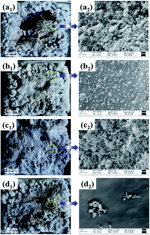 | ||
| Fig. 6 Digital photographs (1) and SEM images (2) of residual chars of ALSR (a), ALSR/α-ZrP (b), ALSR/PMVP (c) and ALSR/F-ZrP-4 (d). | ||
As seen from SEM images in Fig. 6, the residues of ALSR and ALSR/PMVP were both tousy and porous, revealing that PMVP couldn't effectively improve the quality of the residue. When α-ZrP was added, the residue was continuous and flat, but had some cracks, indicating α-ZrP could improve the quality of residue layers to some extent. As for ALSR/F-ZrP-4, the micro-structure of residue was not only continuous and smooth, but also very compact, which was a good barrier to protect the underlying polymer and inhibit the exchange of degradation products, combustible gases and oxygen. The remarkable enhancement of residue surface for ALSR/F-ZrP-4 might be attributed to two aspects. On the one hand, PMVP suppressed the degradation of ALSR by free-radical quenching effect to provide enough silicone chains for the subsequent self-crosslinking reactions. On the other hand, PMVP improved the dispersion of ZrP nanosheets in ALSR, and the good dispersion of F-ZrP significantly enhanced the catalytic efficiency of ZrP to promote silicone chains self-crosslinking, resulting in the formation of the compact ceramic layer.
3.6 TG-IR analysis
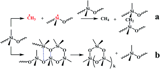
Fig. S1† shows the 3D TG-IR spectra of the pyrolysis gases in the thermal degradation of ALSR (a) and ALSR F-ZrP-4 (b) under air atmosphere, and (c) the FTIR spectra of total volatile products for ALSR and ALSR/F-ZrP-4. For ALSR and ALSR/F-ZrP-4, four main small molecular gaseous species could be identified by their characteristic absorbance: cyclic oligomers (2966 cm−1, 1264 cm−1, 1074 cm−1, 1026 cm−1 and 849 cm−1), methane (3017 cm−1 and 1304 cm−1), CO (2179 cm−1 and 2114 cm−1) and CO2 (2359 cm−1 and 2314 cm−1).32Fig. 7 presents the evolution curves of the pyrolysis products, which are shown as the FTIR absorbance of pyrolysis products versus temperature, respectively. During the thermal degradation of ALSR, the release of CH4 could promote the crosslinking of the polysiloxane molecules,33 as shown in Scheme 1a. Therefore, the increase of CH4 facilitates the formation of tight silicone network. From Fig. 7, it was observed that the addition of F-ZrP significantly increased the evolution of CH4, indicating F-ZrP promoted silicone chains self-crosslinking to generate a compact ceramic layer.
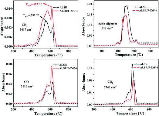 | ||
| Fig. 7 FTIR absorbance versus temperature curves of pyrolysis products evolved from ALSR and ALSR/F-ZrP-4 under air atmosphere. | ||
According to G. Camino, the combustion of SR mainly takes place by the reaction between oxygen and cyclic oligomers to generate CO, CO2 and SiO2.34 In order to further understand the change of the pyrolysis products, the integrated areas of the absorbance peaks of the pyrolysis products are summarized in Table 5. As can be seen, after incorporating F-ZrP, the evolution of the main combustible gas (cyclic oligomers) decreased by 30.9%, which was good in agreement with the improvements in the flame retardancy. However, it was worth noting that on the contrary of the decrease of cyclic oligomers, the release of CO of ALSR/F-ZrP-4 increased by 76.8%, compared with ALSR. This strange phenomenon could be explained by that PMVP interrupted the thermo-oxidation process by the free-radical quenching effect to make cyclic oligomers incomplete oxidative degradation. Fig. S2† shows FTIR absorbance vs. temperature curves of pyrolysis products of ALSR and ALSR/F-ZrP-4 in the nitrogen. As can be seen, there were only two kinds of pyrolysis products (CH4 and cyclic oligomers) during thermal degradation of ALSR in the nitrogen. Compared to ALSR, the evolution of CH4 of ALSR/F-ZrP-4 increased, indicating that F-ZrP promoted silicone chains self-crosslinking to generate a compact ceramic layer, and the evolution of cyclic oligomers of ALSR/F-ZrP-4 significantly decreased. The decrease of cyclic oligomers would give rise to the improvement of flame retardancy of ALSR.
| Sample | Integrated area | ||
|---|---|---|---|
| Cyclic oligomers | CO | CO2 | |
| ALSR | 29.38 | 3.53 | 8.94 |
| ALSR/F-ZrP-4 | 20.31 | 6.24 | 3.88 |
3.7 XPS analysis
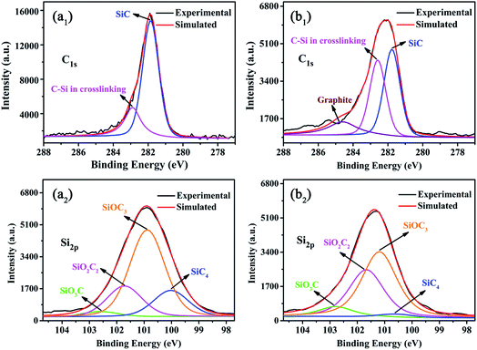
In order to understand how F-ZrP acts in the condensed phase, the residues of ALSR and ALSR/F-ZrP-4 after cone tests are studied by XPS analysis, and the results are shown in Fig. 8. As seen from Fig. 8a1, the C1s peak of the residue of ALSR was split into two peaks. The peak at 281.8 eV was assigned to SiC species.35 The peak at 282.7 eV was attributed to C–Si in the cross-linked network.36 For ALSR/F-ZrP-4, the content of the C–Si structure in the cross-linked network greatly increased, compared with ALSR, indicating F-ZrP effectively promoted silicone chains self-crosslinking with the structure of Si–C–Si. Furthermore, there was a new peak at 284.6 eV in the C1s spectrum of the residue of ALSR/F-ZrP-4, which was assigned to C![[double bond, length as m-dash]](https://www.rsc.org/images/entities/char_e001.gif) C in the graphite.37 As reported, the high content of graphitized carbons was beneficial to enhance the strength and thermostability of the residual chars.38
C in the graphite.37 As reported, the high content of graphitized carbons was beneficial to enhance the strength and thermostability of the residual chars.38
In Fig. 8a2 and b2, for ALSR and ALSR/F-ZrP-4, the Si2p peaks of the residues were both split into 4 peaks. The peak at 100.2 eV was assigned to the structure of SiC4, which might be SiC species.39 The peaks at 101.0 eV, 101.6 eV and 102.4 eV were attributed to C3SiO, C2SiO2 and CSiO3, respectively, which were all contributed to the formation of the cross-linked network with the Si–O–Si structure.40 Compared with ALSR, the most obvious changes in the Si2p peaks of the residue of ALSR/F-ZrP-4 were the great increase of the C2SiO2 structure and the decrease of the SiC4 structure, which further confirmed that F-ZrP promoted silicone chains self-crosslinking with the bridged structure of Si–C–Si and suppressed the formation of SiC. Moreover, the structure of CSiO3 also increased, suggesting that F-ZrP also promoted the polysiloxane molecular chains self-crosslinking with the structure of Si–O–Si.
3.8 Flame retardant mechanism of F-ZrP
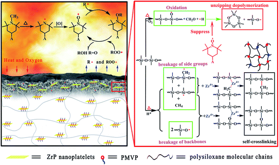
Based on the analysis mentioned above, it was evident that F-ZrP could efficiently enhance the flame retardancy of ALSR mainly due to the synergism of the catalyzing carbonization and free-radical quenching mechanism, as shown in Fig. 9. Owing to their good dispersion in ALSR as well as strong interfacial interactions between F-ZrP and the matrix, F-ZrP nanoplatelets acted as an excellent barrier to reduce the gas permeability, which not only delayed the degradation of the polysiloxane molecule segments, but also protected PMVP from the oxidation in advance. Once PMVP was oxidized to generate nitroxyl radicals, it suppressed the thermo-oxidative degradation of the polysiloxane molecules in the condensed phase and inhibited the chain reactions of the combustion in the gas phase by free-radical quenching effect.When the temperature was further increased, F-ZrP thermally loosed H+, which attacked the polysiloxane molecules to form the macroradicals.18 Meanwhile, Zr4+ of F-ZrP captured macroradicals and lead to intermolecular cross-linking with the bridged structure of Si–C–Si and Si–O–Si, resulting in the formation of the compact and thermostable ceramic layer which acted as an effective barrier against the heat transmission and oxygen diffusion. Furthermore, Zr4+ also promoted the formation of graphitic structure in the outer surface which enhanced the thermostability and strength of ceramic layer.
4. Conclusions
In this work, functionalized zirconium phosphate (F-ZrP) was prepared by the intercalation of PMVP into α-ZrP, and F-ZrP could effectively enhance the flame retardancy of ALSR. When only 4.0 phr F-ZrP was added, the LOI value reached 31.0% and the vertical burning test (UL-94) passed the V-0 rating. Moreover, compared to ALSR, PHRR and THR values of ALSR/F-ZrP-4 decreased by 54.2% and 47.5%, respectively. Such an efficient flame retardancy of F-ZrP was mainly attributed to the synergistic effect between the catalyzing carbonization and free-radical quenching effect. On the one hand, PMVP in the interlayer of F-ZrP was oxidized to generate nitroxyl radicals which retarded the thermal oxidative degradation of polysiloxane molecules in the condensed phase and quenched the active free-radicals in the gas phase; on the other hand, F-ZrP promoted silicone chains self-crosslinking and the formation of the graphitized carbons, leading to the formation of the compact and thermostable ceramic layers, which acted as an effective barrier against the heat transmission and oxygen diffusion.Conflicts of interest
There are no conflicts to declare.Acknowledgements
We greatly acknowledge the National Natural Science Foundation of China (51773064, 51403067, 51573052), the Natural Science Foundation of Guangdong Province (2017A030313303), the Special Funds for the Cultivation of Guangdong College Students' Scientific and Technological Innovation (pdjh2017a0028) for their financial supports.Notes and references
- H. Y. Li, S. Tao, Z. T. Su and J. P. Zheng, Compos. Sci. Technol., 2013, 76, 52–60 CrossRef CAS.
- Z. Sun, Q. Huang, Y. Z. Wang and Y. P. Wu, RSC Adv., 2017, 7, 38915–38922 RSC.
- A. Beaugendre, S. Saidi, M. Casetta and M. Jimenez, RSC Adv., 2017, 7, 40682–40694 RSC.
- I. Butnaru, M. Bruma and S. Gaan, RSC Adv., 2017, 7, 50508–50518 RSC.
- H. S. Devarennes, R. Sonnier and F. Ganachaud, Polym. Degrad. Stab., 2009, 94, 465–495 CrossRef.
- H. J. Sue, K. T. Gam, N. Bestaoui and A. Clearfield, Chem. Mater., 2004, 16, 242–249 CrossRef CAS.
- L. Tong, F. Qiu, T. J. Zeng, T. Sun and Y. Yang, RSC Adv., 2017, 7, 47999–48018 RSC.
- A. Okada and A. Usuki, Macromol. Mater. Eng., 2006, 291, 1449–1476 CrossRef CAS.
- N. I. N. Ismail, A. Ansarifar and M. Song, Polym. Eng. Sci., 2013, 53, 2603–2614 CAS.
- B. Pradhan and S. K. Srivastava, Composites, Part A, 2014, 56, 290–299 CrossRef CAS.
- J. Alongi and A. Frache, Polym. Degrad. Stab., 2010, 95, 1928–1933 CrossRef CAS.
- X. Z. Wang, D. Zhao, A. Diaz and A. Clearfield, Chem. Commun., 2013, 52, 4832–4835 RSC.
- B. M. Mosby, A. Diaz and A. Clearfield, ACS Appl. Mater. Interfaces, 2014, 6, 585–592 CAS.
- C. Zhu, C. Deng, J. Y. Cao and Y. Z. Wang, Polym. Degrad. Stab., 2015, 121, 42–503 CrossRef CAS.
- D. D. Yang, Y. Hu, L. Song and Y. B. Cai, Polym. Degrad. Stab., 2008, 93, 2014–2018 CrossRef CAS.
- Y. J. Zhou, Y. Z. Meng and L. Y. Sun, ACS Appl. Mater. Interfaces, 2014, 6, 7417–7425 CAS.
- J. Alongi, G. Camino and G. Malucelli, J. Anal. Appl. Pyrolysis, 2014, 108, 212–221 CrossRef CAS.
- D. D. Yang, Y. Hu, L. Song and H. P. Xu, J. Therm. Anal. Calorim., 2015, 119, 619–624 CrossRef CAS.
- K. Cao, S. L. Wu and L. Shao, Ind. Eng. Chem. Res., 2013, 52, 309–317 CrossRef CAS.
- H. L. Xie, Y. J. Zhang and X. R. Zeng, Polym. Degrad. Stab., 2015, 118, 167–177 CrossRef CAS.
- L. Y. Sun, W. J. Boo and A. Clearfield, New J. Chem., 2007, 31, 39–43 RSC.
- J. W. Gu, X. D. Meng and J. Kong, Composites, Part A, 2017, 92, 27–32 CrossRef CAS.
- F. Carosio, J. Alongi and G. Malucelli, J. Mater. Chem., 2011, 21, 10370–10376 RSC.
- E. N. Kalali, S. D. Juan and D. Y. Wang, J. Therm. Anal. Calorim., 2015, 121, 619–626 CrossRef CAS.
- L. S. Brandao, L. C. Mendes and M. L. Dias, J. Appl. Polym. Sci., 2006, 102, 3868–3876 CrossRef CAS.
- F. Bauer and M. Willert-Porada, J. Membr. Sci., 2004, 233, 141–149 CrossRef CAS.
- H. L. Xie, X. J. Lai, H. Q. Li and X. R. Zeng, Polym. Degrad. Stab., 2016, 130, 68–77 CrossRef CAS.
- F. Bellezza, A. Cipiciani and M. E. Negozio, Langmuir, 2002, 18, 8737–8742 CrossRef CAS.
- S. S. Chen, X. Li, Y. Li and J. Q. Sun, ACS Nano, 2015, 9, 4070–4076 CrossRef CAS PubMed.
- F. Sun, T. Yu, C. Q. Hu and Y. Li, Compos. Sci. Technol., 2016, 136, 76–84 CrossRef CAS.
- F. P. Lou, L. H. Cheng and W. H. Guo, RSC Adv., 2017, 7, 38805–38811 RSC.
- W. Z. Fang, X. R. Zeng, X. J. Lai and Y. J. Zhang, Thermochim. Acta, 2015, 605, 28–36 CrossRef CAS.
- G. Camino, S. M. Lomakin and M. Lazzari, Polymer, 2002, 43, 2011–2015 CrossRef CAS.
- G. Camino, S. M. Lomakin and M. Lazzari, Polymer, 2001, 42, 2395–2402 CrossRef CAS.
- P. Lv, X. Tang and W. Wei, RSC Adv., 2017, 7, 47116–47124 RSC.
- A. Abdolmaleki, S. Mallakpour and S. Borandeh, Polym. Compos., 2016, 37, 1924–1935 CrossRef CAS.
- J. Alongi, G. Camino and G. Malucelli, Carbohydr. Polym., 2013, 92, 1327–1334 CrossRef CAS PubMed.
- S. B. Zhang and H. J. Wang, J. Therm. Anal. Calorim., 2011, 103, 711–716 CrossRef CAS.
- H. T. Chiua, T. Sukachonmakul and K. Wattanakul, Appl. Surf. Sci., 2014, 292, 928–936 CrossRef.
- R. J. E. Corriu, D. Leclercq and A. Vioux, J. Sol-Gel Sci. Technol., 1997, 327–330 CAS.
Footnote |
| † Electronic supplementary information (ESI) available. See DOI: 10.1039/c7ra11459a |
| This journal is © The Royal Society of Chemistry 2018 |

